EP0227924A2 - Dispositif de régulation de puissance réactive pour commander la puissance réactive et corriger le facteur de puissance - Google Patents
Dispositif de régulation de puissance réactive pour commander la puissance réactive et corriger le facteur de puissance Download PDFInfo
- Publication number
- EP0227924A2 EP0227924A2 EP86115568A EP86115568A EP0227924A2 EP 0227924 A2 EP0227924 A2 EP 0227924A2 EP 86115568 A EP86115568 A EP 86115568A EP 86115568 A EP86115568 A EP 86115568A EP 0227924 A2 EP0227924 A2 EP 0227924A2
- Authority
- EP
- European Patent Office
- Prior art keywords
- reactive power
- network
- voltage
- transformer
- winding
- Prior art date
- Legal status (The legal status is an assumption and is not a legal conclusion. Google has not performed a legal analysis and makes no representation as to the accuracy of the status listed.)
- Withdrawn
Links
Images


Classifications
-
- H—ELECTRICITY
- H02—GENERATION; CONVERSION OR DISTRIBUTION OF ELECTRIC POWER
- H02J—ELECTRIC POWER NETWORKS; CIRCUIT ARRANGEMENTS OR SYSTEMS FOR SUPPLYING OR DISTRIBUTING ELECTRIC POWER; SYSTEMS FOR STORING ELECTRIC ENERGY
- H02J3/00—Circuit arrangements for AC mains or AC distribution networks
- H02J3/18—Arrangements for adjusting, eliminating or compensating reactive power in networks
- H02J3/1878—Arrangements for adjusting, eliminating or compensating reactive power in networks using tap changing or phase shifting transformers
-
- G—PHYSICS
- G05—CONTROLLING; REGULATING
- G05F—SYSTEMS FOR REGULATING ELECTRIC OR MAGNETIC VARIABLES
- G05F1/00—Automatic systems in which deviations of an electric quantity from one or more predetermined values are detected at the output of the system and fed back to a device within the system to restore the detected quantity to its predetermined value or values, i.e. retroactive systems
- G05F1/70—Regulating power factor; Regulating reactive current or power
-
- H—ELECTRICITY
- H02—GENERATION; CONVERSION OR DISTRIBUTION OF ELECTRIC POWER
- H02J—ELECTRIC POWER NETWORKS; CIRCUIT ARRANGEMENTS OR SYSTEMS FOR SUPPLYING OR DISTRIBUTING ELECTRIC POWER; SYSTEMS FOR STORING ELECTRIC ENERGY
- H02J3/00—Circuit arrangements for AC mains or AC distribution networks
- H02J3/12—Arrangements for adjusting voltage in AC networks by changing a characteristic of the network load
- H02J3/16—Arrangements for adjusting voltage in AC networks by changing a characteristic of the network load by adjustment of reactive power
-
- Y—GENERAL TAGGING OF NEW TECHNOLOGICAL DEVELOPMENTS; GENERAL TAGGING OF CROSS-SECTIONAL TECHNOLOGIES SPANNING OVER SEVERAL SECTIONS OF THE IPC; TECHNICAL SUBJECTS COVERED BY FORMER USPC CROSS-REFERENCE ART COLLECTIONS [XRACs] AND DIGESTS
- Y02—TECHNOLOGIES OR APPLICATIONS FOR MITIGATION OR ADAPTATION AGAINST CLIMATE CHANGE
- Y02E—REDUCTION OF GREENHOUSE GAS [GHG] EMISSIONS, RELATED TO ENERGY GENERATION, TRANSMISSION OR DISTRIBUTION
- Y02E40/00—Technologies for an efficient electrical power generation, transmission or distribution
- Y02E40/30—Reactive power compensation
Definitions
- the invention relates to a reactive power control device for reactive power control and power factor correction, consisting of a reactive power compensation device which generates a compensating reactive power as a function of an inductive or capacitive load in the network with a predetermined network voltage via changing capacitive or inductive devices.
- a reactive power control device with the features specified in the preamble of the main claim is known.
- Reactive powers result from an inductive or capacitive load connected to the network.
- an inductive load for example an electric motor, one obtains a lagging reactive power. This lagging reactive power is compensated for by capacitors that provide leading reactive power.
- the size of the compensating leading reactive power should be set equal to the size of the existing lagging reactive power, otherwise the system will be under- or over-compensated.
- a major disadvantage of this capacitor switching technique is that one is forced to compromise and achieve a degree of compensation that deviates from the ideal value or even from an acceptable value. For example, if 6 capacitors were used, the deviation would be 1/12 of the compensatable value.
- overcompensation that is to say a power factor correction greater than 1.0
- overcompensation could result in overvoltages of 40% in the network and subsequent damage to the load, for example to the motor drive devices, under certain operating conditions.
- a further disadvantage is the fact that the capacitors operate at full nominal voltage at all times, and at certain switching stages the peak voltage increases above the value of the nominal peak voltage of the capacitors, which can destroy these capacitors or reduce their service life.
- the invention has for its object to develop a reactive power control device of the type described above so that the compensating reactive power can be controlled continuously with little construction and a power factor of one is achieved.
- the reactive power compensation device is connected in the bypass to the network, contains at least one fixed capacitive or inductive device and a separate supply network which supplies the voltage for the capacitive or inductive device, the separate supply network depending on the in the network existing load, the voltage applied to the capacitive or inductive device automatically continuously continuously such that a compensating reactive power is generated, which changes quadratically with the currently applied voltage.
- the compensatory reactive power of the electrical system is thus regulated by increasing or decreasing the voltage supplied to the capacitive or inductive devices.
- the regulation of the voltage, and thus the compensating reactive power is infinitely variable, which prevents current surges or similar in the network.
- the continuous control enables a power factor of one to be achieved without overvoltages in the network caused by the gradual connection of the inductive or capacitive devices.
- the reactive power control device proposed here is used as a second example.
- a single capacitive device i.e. a single capacitor, with a reactive power of 100 kVAR at 480 V is used.
- Such a capacitor costs approximately 1/4 of a single capacitor with a reactive power of 100 kVAR at 240 V or even less compared to 9 divided capacitors.
- the voltage range of the capacitor used is 480 V to zero.
- Half of this reactive power comes directly from the network, the other half, i. H. 50 kVA, is supplied by the separate supply network.
- the basic range of compensating reactive power is to be omitted.
- a capacitor for 100 kVAR and 360 V is used.
- the lowest voltage supplied to the capacitor is 120 V, the highest 360 V.
- the power of the separate supply network is then 33.3 kVA. This is a saving of 1/3 of the power.
- the 360 V capacitor used here is more trustworthy than the 480 V capacitor with the same reactive power of 100 kVAR.
- a single capacitor can be used, as opposed to multiple capacitors with smaller values.
- a single larger capacitor is host more economical in terms of cost and size as well as effort for assembly and wiring.
- the separate supply network advantageously consists of a series transformer with insulated primary and secondary windings and a variable transformer, the secondary winding of the series transformer being connected in series with the capacitive or inductive device and the variable transformer being connected to the network.
- a variable voltage can be generated in a simple manner with a variable transformer.
- the variable voltage of the variable transformer feeds the primary winding of the series transformer, -
- the primary winding of the series transformer induces a second variable voltage in the secondary winding of the series transformer.
- the voltage of the secondary winding is in phase with the voltage of the network.
- the size of the induced voltage depends on the position of the variable transformer and the transformation ratio of the primary to the secondary winding of the series transformer.
- the voltage supplied to the inductive or capacitive device for the compensating reactive power varies between the size of the mains voltage and the highest available voltage of the secondary winding of the series transformer.
- the voltage can be changed in infinitely small increments at will and thus generates extremely precise values.
- variable voltage is free of any interference when using a variable transformer and a series transformer.
- the feedback signal control can advantageously also consist of a reactive power sensor, which is inserted in the separate supply network and indicates the compensating reactive power. This then directly compares the compensating reactive power with the reactive power caused by the load.
- a reactive power sensor instead of a Z- diode controller, an improved accuracy of the reactive power compensation is achieved, since a z-diode controller, even if it works properly, is associated with larger errors.
- the accuracy of the system advantageously does not depend on the sinusoidal shape or the frequency of the mains voltage, in contrast to a control system with power factor measuring devices, which is frequency-sensitive.
- the variable transformer advantageously has a winding column for each phase of the network, each winding column having an equal number of current collectors, which are arranged offset by 180 ° on the circumference of the winding surface and of which half runs in the opposite direction and for each phase of the Network a capacitive or inductive device is provided.
- the directions in which the current collectors are guided on the variable transformer are reversible. This enables an infinite variation in size and a polarity reversal of the variable voltage in the separate supply network.
- the separate supply network advantageously has control loops which contain a reactive power sensor and a reactive power controller, the reactive power sensor generating a feedback signal which is proportional to the reactive power caused by the load in the network and the reactive power controller from a feedback signal controller which generates a reference signal proportional to the compensating reactive power.
- a comparator which compares the return and reference signal and provides in response thereto an error detection signal and a ervovercyclr S, which controls the regulating transformer in dependence on the error detection signal is.
- control loops advantageously offer the possibility that the reactive power control device can be operated fully automatically.
- the possibility is also provided to intervene manually in the control device.
- the compensating reactive power is continuously regulated in such a way that it virtually completely compensates for the reactive power present in the network caused by the load.
- the accuracy of the compensation depends on the nominal accuracy of the reactive power controller.
- the feedback signal control which generates a reference signal proportional to the compensating reactive power, can consist of a Z-diode controller.
- the Zener diode regulator is powered by the control voltage and has Zener diodes and a potentiometer setting at the output.
- the fixed capacitive device is advantageously a single capacitor, which can have a higher nominal voltage than the network. This reduces the costs of the reactive power control device, since the price for a capacitor per kVA is very much lower if the nominal voltage is increased. This is particularly economical when a high compensating reactive power is required.
- a DC motor is advantageously connected downstream of the servo amplifier.
- the electric motor is controlled by the servo amplifier and in turn moves the current transformer's pantographs.
- the pantographs can be moved at variable speeds and braked dynamically. This ensures that the reactive power control device reacts quickly to changes in the reactive power in the network caused by a load.
- the separate supply network also has an autotransformer in connection and back-up connection, which is fed by the network and the output of which is connected upstream of the secondary winding of the series transformer.
- the voltage applied to the capacitor can be shifted with the help of the autotransformer in accordance with the present circumstances.
- the capacitor voltage can be chosen significantly higher than the available mains voltage. This is important because, for reasons of cost, a capacitor with a higher nominal voltage than the available mains voltage is preferred.
- the autotransformer includes a basic winding and an additional winding.
- the highest voltage that must be equated with the nominal capacitor voltage and that yields the highest leading reactive power is equal to the voltage: voltage of the additional winding to neutral plus voltage of the additional winding to neutral divided by the ratio of the turns of the primary winding to the turns of the secondary winding of the series transformer.
- the lowest voltage achievable with this device, which generates the lowest available leading reactive power is the same: voltage of the additional winding to neutral minus voltage of the additional winding to neutral divided by the ratio of the turns of the primary winding to the turns of the secondary winding of the series transformer.
- the highest voltage can be selected, for example, five times as high as the nominal network voltage if the di-electrical circumstances and the electrical regulations allow it.
- the separate supply network advantageously also contains an step-up transformer which is fed by the low-voltage network and the latter Output is connected before the secondary winding of the series transformer.
- the nominal capacitor voltage can be chosen to be even higher compared to the nominal capacitor voltage when using an autotransformer.
- the additional costs for a further transformer with two windings, that is to say for a step-up transformer, are fully or at least partially offset by the lower costs for the capacitor with a very high nominal voltage.
- the primary winding of the series transformer is advantageously a low-voltage winding and the variable transformer has two windings insulated from each other, one of which is connected in parallel with the network Primary high voltage winding, and the other winding of the variable transformer is a secondary low voltage winding with variable output, which feeds the primary winding of the series transformer.
- the voltage supplied to the capacitor can be selected to be less than the nominal mains voltage.
- a capacitor with a nominal voltage lower than the mains voltage can thus be used in order to reduce the costs.
- a capacitor with a smaller nominal voltage than the mains voltage proves to be more cost-effective in particular if the reactive power to be compensated for is relatively low.
- the variable transformer is advantageously a low-voltage saving transformer
- the primary winding of the series transformer is a low-voltage winding
- the separate supply network contains an insulated two-winding transformer with a fixed transformation ratio, the primary high-voltage winding of which is connected in parallel to the network and whose secondary low-voltage winding feeds the variable transformer.
- This is an alternative to a variable transformer powered by a primary high voltage winding as described above.
- one or the other alternative can be used in the presence of a high-voltage network and a small reactive power to be compensated.
- a start-up control system powered by the network which consists of voltage measuring devices with downstream control devices, release devices and successor devices, the voltage measuring devices with the control devices separating the variable transformer from the network when the power of the network is switched off, in which case the variable transformer becomes a damping load for the primary winding of the series transformer and the secondary winding of the series transformer becomes a primary winding and the primary winding the series transformer becomes a secondary winding, with the control loops of the separate supply network being deactivated at the same time as the variable transformer is disconnected, as a result of which no further compensating reactive power is generated becomes; the enabling devices in connection with the successor devices set the variable transformer to the lowest possible voltage when the power of the network is switched on, reconnect the variable transformer to the mains, with the primary and secondary windings of the series transformer subsequently being switched again according to their original purpose, the successor devices Enable control loops of the separate supply network again and a continuously regulated compensating reactive power is generated again.
- the switch-on control system prevents the capacitors from exploding if, for example, the reactive power control device is reactivated after a power failure. Without the switch-on control system, the capacitor would be added to the existing charge, thereby overloading the capacitor and would eventually be destroyed.
- Measuring devices and control devices are advantageously provided, the measuring devices being connected to the network and generating a signal which is proportional to the differential quotient from the square of the current to the reactive power caused by the load, the control devices being connected to measuring devices and the control loops of the separate supply network, and the Regulate compensating reactive power in such a way that the differential quotient from the current square to the reactive power caused by the load is practically always zero, the measuring devices scanning devices for determining the square of the current flowing in the network and the compensating reactive power, differential measuring devices connected to the network for determining the network flowing current square over time, differential measuring devices connected to the reactive power compensation device for determining the compensating reactive power over time and to the difference ential - measuring devices connected logic circuits including dividing device, which supply a signal proportional to the differential quotient from the current square to the reactive power caused by the load, and the differential measuring device preferably consist of transducers, analog / digital and digital / analog converters, delay devices and subtractors .
- loads are in many cases non-linear due to the use of line-commutated converters, thyristor rectifiers, uninterruptible power supplies and other non-linear circuits.
- the power supply for the overhead lines is often not sinusoidal under today's conditions. Due to these changed conditions, one also has to deal with harmonics of the fundamental frequency. This is no longer about a device performance factor, but about non-linear loads and non-sinusoidal power supplies for the loads.
- this invention sets new criteria for minimizing power losses on land lines with non-linear loads or non-sinusoidal voltages of the power supply - as a replacement for obtaining a device factor "equal to one" for linear loads or for power supply with sinusoidal voltages.
- the devices for determining an emerging initial resonance being connected to the network and comprising a resonance threshold relay, a resonance control relay and a time delay relay such that the resonance threshold relay contains two Has break contacts, the first break contact when activating the devices for determining an emerging initial resonance the circuit of the DE motor for an increase in compensating reactive power interrupts, the second normally closed contact is connected in series with the resonance control relay, a normally closed contact of the resonance control relay is connected in series with the time delay relay preselected delay time;
- the devices for suppressing resonance include an inductance inserted into the network and a power contactor, the power contactor has a make contact which is connected in series with the make contact of the time delay relay and normally short-circuits the inductor; when power is supplied after the preselected delay time, the time delay relay has this short circuit eliminated. This avoids the destructive series resonance between the overhead line and the capacitor and enables continuous and safe operation.
- FIGS. 1, 2, 4, 5, 6 and 7 In the case of sinusoidal mains voltage and / or linear load, in which the network is a single-phase system, the exemplary embodiments in FIGS. 1, 2, 4, 5, 6 and 7 are used.
- the reactive power caused by the load which is usually lagging, is measured by the reactive power sensor and a signal proportional to the reactive power, the feedback signal, is made available to the reactive power controller.
- an error signal is determined which feeds a servo amplifier.
- the servo amplifier in turn regulates the position of the current transformer's pantographs via a DC motor and thus determines the compensating reactive power.
- the exemplary embodiment in FIG. 3 is used.
- the principle of regulation is the same as for a single-phase system, but here the regulation comprises the three phases of the network.
- the reactive power caused by the load is measured in only one phase using a reactive power sensor.
- a separate variable transformer is provided for each phase of the network, the current collectors of which are positioned by the DC motor. This system should be used when the phase load is balanced, such as in single or multiple three-phase asynchronous motors or in synchromotors. If the current is not compensated, the reactive power sensor should have three circuits instead of one circuit.
- the reactive power sensor With its output, the reactive power sensor then feeds the three-phase reactive power to the servo amplifier, which is used as a feedback signal for the servo amplifier, which regulates with its output the position of the DC motor that positions the three-phase pantographs of the three-phase variable transformer, to generate a three phase parallel mean.
- This system is suitable for three-phase loads that do not have to be completely symmetrical.
- the separate supply network shown in FIG. 1 can in principle be used, the control loops corresponding to FIGS. 10, 11 and in addition to FIG. 12 and alternatively FIG. 13 to be carried out.
- the device power factor no longer leads to the optimization of power consumption, power requirement and power availability. Therefore, in the case of non-sinusoidal mains voltage and / or non-linear loads, instead of a good device power factor, a system should be sought which minimizes the wattage losses upstream to the load, minimizes the power consumption and maximizes the available power.
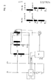
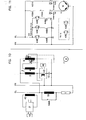
- Fig. 1 shows the simplified representation of the reactive power control device for a Einphasen-System.mit L as phase and N as midpoint or N eutralleiter.
- the system feeds a load 1, which is partially inductive and requires compensation with a leading reactive power.
- the reactive power caused by the load is called a reactive power measured sensor 2, which is connected in series with load 1.
- the reactive power compensation is achieved by a parallel circuit, which comprises a series transformer 3 with a fixed transformation ratio between the primary winding 4 and the secondary winding 5, a variable transformer 6 with two current collectors 7 and 8, a fuse 9 and a capacitor 10.
- the secondary winding 5 of the series transformer 3 with a fixed transformation ratio is connected in series with the fuse 9 and the capacitor 10.
- the primary winding 4 of the series transformer 3 is fed via the current collectors 7 and 8 of the variable transformer 6.
- the variable transformer 6 is a column transformer, the current collectors 7 and 8 are preferably equipped with carbon rollers that slide on the windings of the column transformer. These current collectors 7 and 8 are driven by a DC motor 11 via bevel gear and drive spindles in such a way that when the current collector 7 moves upwards, the current collector 8 moves in the opposite direction at the same speed.
- the current collectors 7 and 8 are offset by 180 ° on the circumference of the winding surface of the variable transformer 6, so that when the current collector 7 slides on the front of the winding surface, the current collector 8 slides in the opposite direction on the back of the winding surface.
- the variable transformer 6 is fed via the fixed connections of the network LN.
- both are on the same turn of the variable transformer 6, and the resulting voltage across the pantographs 7 and 8 becomes zero.
- the pantograph 7 has reached one end of the winding column, for example above, and accordingly, the current collector 8 has reached the lower end, the voltage between the current collectors 7 and 8 becomes equal to the mains voltage, and the mains voltage is fed into the primary winding 4 of the series transformer 3.
- This voltage induces a specific voltage in the secondary winding 5 of the series transformer 3, the voltage magnitude depending on the ratio of the primary winding 4 to the secondary winding 5.
- the voltage supplied to the capacitor 10 varies between the magnitude of the mains voltage and the highest available voltage from the secondary winding 5 of the series transformer 3.
- the voltage can be changed as desired, for example manually, by push button control or automatically by control loops 12, which are connected to the reactive power sensor 2 and the DC motor 11.
- the voltage change can be carried out in infinitely small steps in both cases and thereby generates an extremely precise compensating reactive power.
- the voltage supplied to the capacitor 10 and thus the compensating reactive power can be varied in a range that extends from maximum to down to zero. In practice, however, this lower limit is never required. This lower limit can advantageously be shifted upwards with the reactive power compensation device, as a result of which the size and consequently also the costs are reduced.
- a further cost saving is given by the possibility of using a capacitor 10 with a high nominal voltage. It is known that the higher the nominal voltage of the condenser 10, the lower its capacity in microfarat with the same power and consequently the lower price.
- FIG. 2A shows a variant, in which the variable transformer 6 is fed from a tap of the auxiliary winding 15 of the autotransformer 13, ie from a potential which is lower than in Fig. 2. The lowest practicable potential is the point at which the base winding 14 of the autotransformer 13 is connected to the additional winding 15.
- FIG. 2B shows a variant in which the variable transformer 6 is fed by a potential which is higher than that in FIG. 2.
- Fig. 3 shows the same system as Fig. 2, but adapted to a three-phase four-wire network. All transformers should preferably be three-phase or ring type. Otherwise the mode of operation is the same as described in FIG. 2.
- the control loops 12 are the same as in FIGS. 1 and 2.
- the reactive power sensor 2 is shown in FIG. 2 in an embodiment which also applies to a balanced four-wire network.
- a reactive power sensor 2 corresponding to the design shown here must be used for uneven loads in the individual network phases L1, L2, L3.
- the reactive power sensor 2 has a simple current path in the interrupted line of the line phase L3. It also has three power supplies, one from the line phase L1 neutral, the second from line phase L2 to neutral and the third from line phase L3 to neutral. In a three-phase four-wire network with unbalanced load, these three voltage supplies are required, but also three current paths, which means that all three phases L1, L2, L3 are interrupted in the manner shown for phase L3. In contrast, in a three-phase three-wire network with balanced load, only one current path and only one voltage path are required.
- variable transformer 6 is designed as a ring variable transformer in an economy circuit with center tap.
- a variable ring transformer 6 offers the advantage that it is inexpensive on the one hand and commercially available on the other hand. However, it has only a limited power size and in the event of a parallel connection, the individual ring variable transformers 6 must be reduced in power.
- FIG. 5 shows a solution in which the mains voltage remains within the low-voltage range, ie below 1.2 kV, while a capacitor 10 is provided as a high-voltage capacitor, for example 15 kV, for reasons of cost.
- the system is similar to the system shown in Figure 1, except that an step-up transformer 16 has been inserted with the primary winding 17 and the secondary winding 18, the primary winding 17 being the low voltage winding and the secondary winding 18 being the high voltage winding.
- the circuit of the secondary winding 18 is isolated from that of the primary winding 17 accordingly.
- the only disadvantage when using a step-up transformer 16 is the additional ones Costs for this transformer which are higher than for an autotransformer 13. However, these additional costs are fully or at least partially offset by the lower costs for the capacitor 10 for an even higher voltage than, for example, in FIG. 2.
- Fig. 6 shows a case where the line voltage is a high voltage, for example 15 kV.
- a variable transformer 6 with two windings, a primary high-voltage winding 19 and a secondary low-voltage winding 20, is used.
- FIG. 7 a two-winding transformer 21 with the primary high-voltage winding 19 and the secondary low-voltage winding 22 is provided in FIG. 7.
- the primary high-voltage winding 19 and the secondary low-voltage winding 2 feed the variable transformer 6, which is designed as a low-voltage transformer. With this arrangement, a lower voltage is applied to the capacitor 10 than is present in the network.
- the DC motor 1 drives the current collectors 7 and 8 (not shown here), that is to say current collectors 7 upwards and 8 downwards when the DC motor 11 rotates to the right, current collectors 8 up and 7 down when he turns left.
- the DC motor 11 causes clockwise (increasing) and left-rotating (decreasing) winding positions.
- the reactive power sensor 2 has two current terminals, which are inserted into the mains line L. It has two potential terminals, one is connected to the mains cable L, the other to neutral N.
- Transducers are omitted for simplicity and understanding, although in practice current sensing via a current transformer is essential and in many cases a voltage transformer is required.
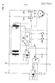
- the feedback signal 23 generated by the reactive power sensor 2 is received by the reactive power controller 24.
- the reactive power controller 24 has a reference signal 25 fed by the control voltage L, N. This reference signal usually has 25 Z diodes
- the reactive power controller 24 further includes a feedback signal controller 26, which receives the feedback signal 23 from the reactive power sensor 2, a comparator 27 and a servo amplifier 28.
- the reference signal 25 and the feedback signal 23 are compared in the comparator 27 and a positive or negative error signal 29 is generated.
- the error signal 29 is then passed into the servo amplifier 28.
- the controlled and amplified signal either feeds the coil of relay K 30 (falling) or the coil of relay K 31 (rising).
- the coil of the K 30 relay is supplied, the corresponding K 30A make contact closes.
- the current from control voltage L flows via a normally closed limit switch 32 to that winding of the DC motor 11 which causes a counterclockwise rotation.
- the rotation of the DC motor 11 causes the pantograph 7 to slide down and the pantograph 8 to slide up, which causes a reduction in the voltage supplied to the capacitor 10.
- the rotation stops when the reactive power compensation - has reached the set value, and at this time the error signal 29 is almost zero, and as close to zero as permitted by the N enngenautechnik of the reactive power controller 24th If the error signal 29 becomes zero, the coil of the relay K 30 is de-energized, the corresponding contact K 30A opens and the feed line to the "left-turning" winding of the DC motor 11 is interrupted, the DC motor 11 stops, as well as the movement of the pantographs 7 and 8, the voltage change and the reactive power correction. After that, the process of power factor correction is practically complete. All of these processes also stop when the current collectors 7 and 8 reach their mechanical end position and thereby open the normally closed limit switches 32/33.
- the reactive power sensors 34 and 35 are used, which do not necessarily have to be of the same type.
- the reactive power sensor 34 is inserted into the load circuit and determines the magnitude of the reactive power caused by the load and whether it is leading or lagging.
- the reactive power sensor 35 is inserted into the parallel circuit for reactive power compensation and accordingly determines the size of the compensating reactive power and whether it is leading or lagging with respect to the mains voltage.
- the reactive power sensors 34 and 35 are each provided with a voltage sensor that ends in a voltage converter. For the sake of clarity, only the voltage sensor lines and their connections are shown in FIG. 9.
- the reactive power sensors 34 and 35 each have a current converter 36 and 37, which is shown as a coil.
- the reactive power sensor 34 is burdened by a potentiometer 38, as a result of which a given feedback signal 23 can be gradually reduced.
- the full feedback signal 23 indicates the total reactive power generated by the load.
- the consumer 39 of the potentiometer 38 is connected to one of the two inputs of the comparator 27.
- the system is arranged in such a way that when the customer 39 is fully adjusted, the corrected power factor becomes one. The further the customer 39 is removed from its "full exit" position, the lower the regulated power factor.
- the reactive power sensor 35 is inserted in the parallel circuit for the compensating reactive power. It generates a reference signal 25 which is compared in the comparator 27 with the feedback signal 23 from the consumer 39.
- the comparator 27 generates a positive or negative error signal 29 therefrom. With such an arrangement, a Z-diode controller can be dispensed with, which achieves higher accuracy.
- the reactive power caused by the load and the compensating reactive power are measured directly by the reactive power sensors 34 and 35 and compared with one another. Furthermore, this system is not dependent on the sinusoidal shape or the frequency of the mains voltage.
- the transmitter for the load is preferably a double transmitter and the same applies to the compensation circuit lying in parallel.
- the load transmitter is preferably a triple transmitter, while a double transmitter is sufficient for the parallel compensation circuit, even for uneven load.
- three single-phase reactive power compensation devices with three individual reactive power sensors are used per load or in parallel horizontal compensation circuit used.
- electromechanical relays K 30 and K 31 electronic relays can be used.
- the "up" - “down” relays are locked using auxiliary contacts to make the control circuit safe from switching.
- P-I-D proportional-integral-differential
- a microprocessor can of course also be used. This would then sample the lagging reactive power plus the leading reactive power using a three-point control,. in which the control process is interrupted until the ratio of the leading to the lagging reactive power has changed.
- a microcomputer can also be used for the control.
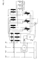
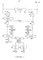
- Fig. 10 is a modification of the basic circuit of one phase of a three-phase system.
- a current converter 40 is inserted into the mains line L, the secondary winding of which feeds a commercially available AC converter 41.
- the AC converter 41 supplies a signal proportional to the load current of the mains line L to measuring devices 42, which are described in more detail in FIG. 12.
- an inductance 51 for resonance suppression is inserted into the mains supply line L, which is normally short-circuited via the contact of the contactor K 50A.
- a variable transformer 6 is inserted in an economy circuit, which feeds the primary winding 4 of the series transformer 3 with a fixed transformation ratio and whose secondary winding 5 is in turn connected in series with the capacitor 10.
- the current path of a reactive power sensor 43 the voltage path of which is connected to the terminals of the capacitor 10, is inserted in the circuit of the capacitor 10.
- another current transformer is inserted into the current path, which has been omitted here for the sake of clarity.
- the output of the reactive power sensor 43 supplies a signal which is proportional to the compensated reactive power and is fed to the measuring device 42 described in FIG. 12.
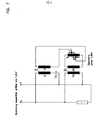
- FIG. 11 a further illustration of FIG. 9, shows the circuit of the DC motor 11, which drives the current collectors 7 and 8 of the variable transformer 6 in an economy circuit corresponding to FIG. 10 or FIG. 1.
- the coil of the relay K 30 has a normally open contact K 30A, which feeds the left-hand winding of the DC motor 11.
- the clockwise winding of the DC motor 11 is fed by the normally open contact K 31A of the coil of the relay K 31.
- a resonance threshold relay K44 receives a signal from the measuring devices 42 which is proportional to the differential quotient from the current square at the time.
- a normally closed contact K 44A of the resonance threshold relay K 44 inserted into the clockwise line of the DC motor 11, interrupts its clockwise function when a predetermined threshold is reached.
- a second normally closed contact K 44B of the resonance threshold relay K 44 feeds a resonance control relay K 46 at the same time in a separate circuit 45.
- the normally closed contact K 46A closes in a second separate circuit 47 and feeds a time delay relay K 48
- the predetermined delay time closes the normally closed contact K 48A of the time delay relay K 48 in a third separate circuit 49 and feeds the power contactor K 50.
- the resonance threshold relay K 44 has detected the resonance threshold of a dangerous initial value from the differential quotient of the current square over time and the normally closed contact K 44A has opened the danger is over.
- the power factor correction is stopped.
- the inductance 51 which is normally short-circuited via the normally closed contact K 50A of the power contactor K 50, as shown in FIG. 10, changes the reactance of the power line and thus prevents resonance.
- the coils of the resonance threshold relay K 44, the resonance control relay K 46 and the time delay relay K 48 are de-energized.
- the normally closed contact K 48A of the time delay relay K 48 remains closed, the power contactor K 50 continues to be supplied and its normally closed contact K 50A remains open.
- the normally closed contact K 44A remains closed, the normally closed contacts K 44B and K 46A remain open. This causes the "clockwise" movement of the DC electric motor 11 to be resumed and the process of improving the power factor to continue until the power factor has become one.
- An analog-to-digital converter 52 which is supplied by the AC converter 41, feeds a commercially available square circuit 53, the rectified output signal of which is proportional to the current square (I 2 ).
- the sampling rate of I 2 is relatively slow compared to the frequency of the network, for example two periods per second.
- a counter 54 samples I 2 at a rate sufficient to detect any changes in the average, for example at a rate of ten samples per second.
- An AND gate 55 which receives the I 2 signal, and an AND gate 56, which receives the signal of the reactive power sensor 43 digitized via an analog-digital converter 57, are both scanned by the counter 54.
- the output of the AND gate 55 which forms the I 2 signal sampled by the counter 54, feeds, on the one hand, directly to an input of a subtractor 58 and, on the other hand, to a second input of the subtractor 58 via a delay circuit, which is composed of a digital-to-analog converter 59 , a delay 60 and an analog-to-digital converter 61.
- the total delay of this delay circuit is 1 / f, where f is the sampling frequency of the counter 54. Accordingly, the subtractor 58 has at its output a signal which is proportional to the differential quotient from the current square at the time.
- an analog-to-digital converter 57 supplied by the reactive power sensor 43 feeds an AND gate 56 and an input of a subtractor 62 directly, while a second input of the subtractor 62 is fed via a delay circuit, which is composed of a digital-to-analog converter 63 , a delay 64 and an analog-to-digital converter 65.
- a signal appears at the output of the subtractor 62, which is proportional to the differential quotient from the reactive power over time.
- the output of subtractor 62 feeds an input of a commercially available logic divider 66, while the second input of logic divider 66 receives the output of subtractor 58 in such a way that a digitized signal appears at the output of logic divider 66 which is proportional to is the differential quotient from the current square to the reactive power.
- This digitized signal is converted by a digital-to-analog converter 67 into an analog signal.
- the output of the digital-to-analog converter 67 feeds the rectifiers 68 and 69 via an insulation circuit (not shown).
- the output of rectifier 68 gives a negative signal
- the output of rectifier 69 gives a positive signal. Turn feed these outputs': the coil of the relay K 30 and K 31st
- FIG. 13 shows a second embodiment for determining the differential quotient from the current square to the reactive power.
- the signal generated by the AC converter 41, FIG. 10 is digitized by the analog-to-digital converter 52 and made available to the input of a low-pass filter 70.
- the output of the low-pass filter 70 is fed to a sample and hold circuit 71.
- the Signal generated by the sampler and hold circuit 71 is supplied to an AND gate 74 via a current comparator 72 and a squarer 73.
- a second output of the low-pass filter 70 and a second output of the current comparator 72 are connected to a threshold element 75 for the lower threshold and a threshold element 76 for the upper threshold.
- the signal generated by the reactive power sensor 43 and digitized by the analog-digital converter 57 is made available to a low-pass filter 77.
- the output of the low-pass filter 77 is coupled to an AND gate 78.
- the counter 54 goes into a second input of the AND element 78 and of the AND element 74.
- the outputs of the AND elements 74 and 78 are connected to a programmable sequence controller 79, the connections to the disconnectors 32 and 33 and the resonance clamp relay K 44 has and consists of subtractors 80 and 81 and divider 82.
- the output signal of the programmable sequence controller 79 which is proportional to the differential quotient from the current square to the reactive power, is converted by a digital-to-analog converter 83 and applied to an optocoupler 84. If the signal is negative, it is connected to the input of relay K 30 via rectifier 68; if it is positive, it is connected to relay K 31 via rectifier 69.
Landscapes
- Engineering & Computer Science (AREA)
- Power Engineering (AREA)
- Physics & Mathematics (AREA)
- Electromagnetism (AREA)
- General Physics & Mathematics (AREA)
- Radar, Positioning & Navigation (AREA)
- Automation & Control Theory (AREA)
- Control Of Electrical Variables (AREA)
Applications Claiming Priority (2)
| Application Number | Priority Date | Filing Date | Title |
|---|---|---|---|
| US799162 | 1985-11-18 | ||
| US06/799,162 US4672298A (en) | 1983-05-06 | 1985-11-18 | Power factor correction system |
Publications (2)
| Publication Number | Publication Date |
|---|---|
| EP0227924A2 true EP0227924A2 (fr) | 1987-07-08 |
| EP0227924A3 EP0227924A3 (fr) | 1989-04-05 |
Family
ID=25175187
Family Applications (1)
| Application Number | Title | Priority Date | Filing Date |
|---|---|---|---|
| EP86115568A Withdrawn EP0227924A3 (fr) | 1985-11-18 | 1986-11-10 | Dispositif de régulation de puissance réactive pour commander la puissance réactive et corriger le facteur de puissance |
Country Status (2)
| Country | Link |
|---|---|
| US (1) | US4672298A (fr) |
| EP (1) | EP0227924A3 (fr) |
Cited By (1)
| Publication number | Priority date | Publication date | Assignee | Title |
|---|---|---|---|---|
| DE102012011246A1 (de) * | 2012-06-06 | 2013-12-12 | Robert Bosch Gmbh | Verfahren zum Betrieb eines Schweissumrichters und Vorrichtung |
Families Citing this family (40)
| Publication number | Priority date | Publication date | Assignee | Title |
|---|---|---|---|---|
| US4982147A (en) * | 1989-01-30 | 1991-01-01 | State Of Oregon Acting By And Through The State Board Of Higher Education On Behalf Of Oregon State University | Power factor motor control system |
| US4994684A (en) * | 1989-01-30 | 1991-02-19 | The State Of Oregon Acting By And Through The State Board Of Higher Education On Behalf Of Oregon State University | Doubly fed generator variable speed generation control system |
| US5239251A (en) * | 1989-06-30 | 1993-08-24 | The State Of Oregon Acting By And Through The State Board Of Higher Education On Behalf Of Oregon State University | Brushless doubly-fed motor control system |
| US5028804A (en) * | 1989-06-30 | 1991-07-02 | The State Of Oregon Acting By And Through The State Board Of Higher Education On Behalf Of Oregon State University | Brushless doubly-fed generator control system |
| US4982148A (en) * | 1989-12-01 | 1991-01-01 | Engelmann Rudolph H | Power factor maintenance system |
| US5081591A (en) * | 1990-02-28 | 1992-01-14 | Westinghouse Electric Corp. | Optimizing reactive power distribution in an industrial power network |
| US5105327A (en) * | 1990-05-10 | 1992-04-14 | Uses, Inc. | Ac power conditioning circuit |
| US5083077A (en) * | 1990-07-31 | 1992-01-21 | The State Of Oregon Acting By And Through The State Board Of Higher Education On Behalf Of Oregon State University | Brushless doubly-fed generation system for vehicles |
| US5424626A (en) * | 1992-04-16 | 1995-06-13 | Remtech Co. | Tuned A.C. power systems compensator having variable reflective impedance for linear and non-linear reactive load compensation |
| US5434496A (en) * | 1992-07-23 | 1995-07-18 | Remtech Co. | A.C. induction devices having compound resistive coupling of tuned reflux winding to neutral or electrical ground |
| EP0881758B1 (fr) * | 1994-04-08 | 2004-06-23 | Vlt Corporation | Conversion de puissance à haut rendement |
| US5646512A (en) * | 1995-08-30 | 1997-07-08 | Beckwith; Robert W. | Multifunction adaptive controls for tapswitches and capacitors |
| US5847942A (en) * | 1996-05-30 | 1998-12-08 | Unitrode Corporation | Controller for isolated boost converter with improved detection of RMS input voltage for distortion reduction and having load-dependent overlap conduction delay of shunt MOSFET |
| US5801460A (en) * | 1996-07-18 | 1998-09-01 | Sundstrand Corporation | Electrical power transmitting system with reduced feeder size and method of operation |
| GB9811517D0 (en) * | 1998-05-28 | 1998-07-29 | Nat Grid Comp Plc | Reactive power compensation |
| US7161257B2 (en) * | 2004-03-08 | 2007-01-09 | Ingersoll-Rand Energy Systems, Inc. | Active anti-islanding system and method |
| US20070247103A1 (en) * | 2006-04-22 | 2007-10-25 | John Lottman Shudde | Method and Apparatus for Controlling Power Supply to Induction Motors |
| EP2321885A2 (fr) * | 2008-08-14 | 2011-05-18 | Simplure, Llc. | Systèmes et procédés pour conditionner et contrôler une consommation d'électricité |
| US8698433B2 (en) * | 2009-08-10 | 2014-04-15 | Emerson Climate Technologies, Inc. | Controller and method for minimizing phase advance current |
| US8264192B2 (en) | 2009-08-10 | 2012-09-11 | Emerson Climate Technologies, Inc. | Controller and method for transitioning between control angles |
| US8508166B2 (en) | 2009-08-10 | 2013-08-13 | Emerson Climate Technologies, Inc. | Power factor correction with variable bus voltage |
| US20110203103A1 (en) * | 2010-02-25 | 2011-08-25 | Steven Bruce Fish | Method of installing a capacitor to a service entrance panel to reduce kw consumption |
| BR112013013160A2 (pt) * | 2010-12-01 | 2016-08-23 | Abb Technology Ag | compensador de energia reativa, programas de computador e produtos de programa de computador |
| US8866575B2 (en) | 2011-01-28 | 2014-10-21 | Uses, Inc. | AC power conditioning circuit |
| US8791782B2 (en) | 2011-01-28 | 2014-07-29 | Uses, Inc. | AC power conditioning circuit |
| CN102810867A (zh) * | 2011-05-30 | 2012-12-05 | 青岛海电电气有限公司 | 基于磁控电抗器的动态无功补偿系统 |
| US9160172B2 (en) * | 2011-10-12 | 2015-10-13 | General Electric Company | Systems and methods for adaptive possible power determinaton in power generating systems |
| US9634593B2 (en) | 2012-04-26 | 2017-04-25 | Emerson Climate Technologies, Inc. | System and method for permanent magnet motor control |
| CA2878612C (fr) * | 2012-07-12 | 2021-07-27 | General Electric Company | Systeme de freinage dynamique pour un systeme de generation d'electricite et son procede de fonctionnement |
| WO2014026124A1 (fr) | 2012-08-10 | 2014-02-13 | Emerson Climate Technologies, Inc. | Commande d'entraînement de moteur utilisant une suppression d'impulsion de modulation d'impulsions en largeur |
| EP2765698B1 (fr) * | 2013-02-06 | 2018-10-24 | Siemens Aktiengesellschaft | Agencement pour l'allumage de tiges fines à base de matériau conducteur électrique, en particulier de tiges fines de silicium |
| JP6280634B2 (ja) * | 2013-03-30 | 2018-02-14 | エッジ エレクトロンズ リミテッド | 微分キャパシタ切替およびライントランジェントノイズの減少による受動力率補償方法のためのアルゴリズム |
| US11320845B2 (en) * | 2013-12-27 | 2022-05-03 | Beckwith Electric Co., Inc. | Smart voltage reduction and reverse power operating mode determination for load tap charging transformers and voltage regulators |
| CN104050366B (zh) * | 2014-06-13 | 2017-09-01 | 国家电网公司 | 一种动态无功补偿装置响应时间测试方法 |
| KR20170139399A (ko) * | 2016-06-09 | 2017-12-19 | 엘에스산전 주식회사 | 무효 전력 보상 시스템 및 그 방법 |
| MY200003A (en) * | 2017-08-09 | 2023-12-04 | Tan Soh Peng | Assembly for suppressing reactive power loss |
| US10686369B1 (en) | 2019-07-24 | 2020-06-16 | Dean Hatsuo Motoyama | Device and process for detecting and mitigating reverse power-flow |
| BR112022013754A2 (pt) | 2020-01-14 | 2022-10-11 | Adventech Llc | Métodos para estabelecer uma rede de dispositivos elétricos eficientemente energizados e para fornecer um motor de indução operacionalmente estável, rede de dispositivos elétricos eficientemente energizados, motor de indução, e, sistema de motor de indução de enrolamento reverso de partida progressiva. |
| CN118648228A (zh) | 2021-12-16 | 2024-09-13 | 赛峰乘客创新有限公司 | 用于自适应有源功率因数校正的系统和方法 |
| CN114336669B (zh) * | 2022-03-14 | 2022-06-03 | 东方博沃(北京)科技有限公司 | 一种快速无功补偿的控制方法、装置、设备及存储介质 |
Family Cites Families (3)
| Publication number | Priority date | Publication date | Assignee | Title |
|---|---|---|---|---|
| US3422343A (en) * | 1966-11-21 | 1969-01-14 | Westinghouse Electric Corp | Reactive power compensation by phase angle control and tap changer means |
| US4438387A (en) * | 1981-06-08 | 1984-03-20 | Frederick Rohatin | Turn-on control system for voltage drop compensators |
| US4554502A (en) * | 1983-05-06 | 1985-11-19 | Frederick Rohatyn | Power factor correction system |
-
1985
- 1985-11-18 US US06/799,162 patent/US4672298A/en not_active Expired - Lifetime
-
1986
- 1986-11-10 EP EP86115568A patent/EP0227924A3/fr not_active Withdrawn
Cited By (2)
| Publication number | Priority date | Publication date | Assignee | Title |
|---|---|---|---|---|
| DE102012011246A1 (de) * | 2012-06-06 | 2013-12-12 | Robert Bosch Gmbh | Verfahren zum Betrieb eines Schweissumrichters und Vorrichtung |
| US9302342B2 (en) | 2012-06-06 | 2016-04-05 | Robert Bosch Gmbh | Method for operating a welding converter and apparatus |
Also Published As
| Publication number | Publication date |
|---|---|
| EP0227924A3 (fr) | 1989-04-05 |
| US4672298A (en) | 1987-06-09 |
Similar Documents
| Publication | Publication Date | Title |
|---|---|---|
| EP0227924A2 (fr) | Dispositif de régulation de puissance réactive pour commander la puissance réactive et corriger le facteur de puissance | |
| DE69611176T2 (de) | Verfahren und vorrichtung für die stufenlose einstellung und regulierung des windungsverhältnises eines transformatores und transformator mit einer solchen vorrichtung | |
| DE3787335T2 (de) | Schema zum schnellen einstellen der netzimpedanz. | |
| DE2653333C2 (de) | Anordnung zur stufenlosen Kompensation von Blindleistung in einem elektrischen Wechselspannungsnetz | |
| EP0152002B1 (fr) | Déphaseur | |
| DE69321769T2 (de) | Geregelter schaltnetzteil | |
| EP1493921A1 (fr) | Procede d'exploitation d'une installation d'energie eolienne | |
| DE3225285A1 (de) | Verfahren zum betrieb einer hochspannungs-gleichstromuebertragungsanlage mit beliebig vielen umformerstationen | |
| DE1943646C3 (de) | Regelanordnung zur Vermeidung der bei einem Lastabwurf einer Hochspannungs-Gleichstrom-Übertragungsanlage auftretenden netzfrequenten Spannungsüberhöhung | |
| DE2901263A1 (de) | Regelung einer hgue-(hochspannungs- gleichstrom-uebertragungs-)-kurzkupplung | |
| EP1927186B1 (fr) | Procede de reglage pour une transmission de courant continu a l'aide de plusieurs convertisseurs de courant | |
| DE2538493C3 (de) | Gegen Überstrom geschützte Hochspannungsgleichstromübertragungsanlage | |
| DE69728406T2 (de) | Adaptive Multifunktionssteuerungen für Stufenschalter und Kondensatoren | |
| WO2015169692A2 (fr) | Installation et procédé pour fournir une puissance réactive | |
| EP0053413B1 (fr) | Dispositif pour la commande continue de l'angle de phase dans des installations de transmission d'énergie électrique | |
| EP0701743A1 (fr) | Procede et dispositif permettant de reduire les tensions asymetriques dans un reseau triphase au moyen d'un compensateur statique | |
| DE3034498A1 (de) | Leistungsfaktor-verbesserungseinrichtung fuer stromrichter | |
| EP0165898A2 (fr) | Dispositif pour remédier à disparition de la tension alternative de réseau | |
| WO2023217505A1 (fr) | Dispositif et procédé d'adaptation d'un angle de phase d'une tension dans une ligne de transmission | |
| DE3115097C1 (de) | Eisendrossel mit Luftspalt zum Anlassen eines ein- oder mehrphasigen Kurzschlußläufermotors mit kleinem Anfahrmoment | |
| DE2626096C3 (de) | Einrichtung zum Anlassen von ein- oder mehrphasigen Kurzschlußläufermotoren | |
| DE2162988C3 (de) | Stellglied für einen Wechselspannungsregler | |
| DE1943840C3 (de) | Vorrichtung zum Verbinden zweier Wechselstromnetze | |
| DE2730010C2 (de) | Schaltungsanordnung zur Erzeugung nach Größe und Kurvenform schnell veränderbarer Blindströme | |
| DE3446847C1 (de) | Spannungsregelungseinrichtung für die Sammelschiene eines Umspannwerkes |
Legal Events
| Date | Code | Title | Description |
|---|---|---|---|
| PUAI | Public reference made under article 153(3) epc to a published international application that has entered the european phase |
Free format text: ORIGINAL CODE: 0009012 |
|
| AK | Designated contracting states |
Kind code of ref document: A2 Designated state(s): AT BE CH DE ES FR GB GR IT LI LU NL SE |
|
| PUAL | Search report despatched |
Free format text: ORIGINAL CODE: 0009013 |
|
| RHK1 | Main classification (correction) |
Ipc: H02J 3/18 |
|
| AK | Designated contracting states |
Kind code of ref document: A3 Designated state(s): AT BE CH DE ES FR GB GR IT LI LU NL SE |
|
| 17P | Request for examination filed |
Effective date: 19890318 |
|
| 17Q | First examination report despatched |
Effective date: 19910115 |
|
| RBV | Designated contracting states (corrected) |
Designated state(s): AT BE DE ES FR GB GR IT NL SE |
|
| STAA | Information on the status of an ep patent application or granted ep patent |
Free format text: STATUS: THE APPLICATION IS DEEMED TO BE WITHDRAWN |
|
| 18D | Application deemed to be withdrawn |
Effective date: 19920602 |
|
| RIN1 | Information on inventor provided before grant (corrected) |
Inventor name: ROHATYN, FREDERICK |