EP0227935B1 - Chambre de combustion pour moteur à combustion interne - Google Patents
Chambre de combustion pour moteur à combustion interne Download PDFInfo
- Publication number
- EP0227935B1 EP0227935B1 EP86116004A EP86116004A EP0227935B1 EP 0227935 B1 EP0227935 B1 EP 0227935B1 EP 86116004 A EP86116004 A EP 86116004A EP 86116004 A EP86116004 A EP 86116004A EP 0227935 B1 EP0227935 B1 EP 0227935B1
- Authority
- EP
- European Patent Office
- Prior art keywords
- combustion chamber
- main
- sub
- fuel
- chamber
- Prior art date
- Legal status (The legal status is an assumption and is not a legal conclusion. Google has not performed a legal analysis and makes no representation as to the accuracy of the status listed.)
- Expired - Lifetime
Links
- 238000002485 combustion reaction Methods 0.000 title claims description 149
- 239000000446 fuel Substances 0.000 claims description 72
- 238000002347 injection Methods 0.000 claims description 6
- 239000007924 injection Substances 0.000 claims description 6
- 239000003595 mist Substances 0.000 description 9
- CIWBSHSKHKDKBQ-JLAZNSOCSA-N Ascorbic acid Chemical compound OC[C@H](O)[C@H]1OC(=O)C(O)=C1O CIWBSHSKHKDKBQ-JLAZNSOCSA-N 0.000 description 7
- 238000004891 communication Methods 0.000 description 7
- 238000010304 firing Methods 0.000 description 6
- 239000000295 fuel oil Substances 0.000 description 5
- 239000007789 gas Substances 0.000 description 5
- 239000000203 mixture Substances 0.000 description 5
- 239000003921 oil Substances 0.000 description 5
- 230000015572 biosynthetic process Effects 0.000 description 4
- 238000010276 construction Methods 0.000 description 4
- 239000002245 particle Substances 0.000 description 4
- 239000000779 smoke Substances 0.000 description 3
- LFQSCWFLJHTTHZ-UHFFFAOYSA-N Ethanol Chemical compound CCO LFQSCWFLJHTTHZ-UHFFFAOYSA-N 0.000 description 2
- 239000000567 combustion gas Substances 0.000 description 2
- 230000002093 peripheral effect Effects 0.000 description 2
- 230000000644 propagated effect Effects 0.000 description 2
- 230000006866 deterioration Effects 0.000 description 1
- 230000003292 diminished effect Effects 0.000 description 1
- 230000000694 effects Effects 0.000 description 1
- 239000010419 fine particle Substances 0.000 description 1
- 239000012530 fluid Substances 0.000 description 1
- 230000006872 improvement Effects 0.000 description 1
- 230000006911 nucleation Effects 0.000 description 1
- 238000010899 nucleation Methods 0.000 description 1
- 238000005086 pumping Methods 0.000 description 1
- 239000000243 solution Substances 0.000 description 1
- 239000007921 spray Substances 0.000 description 1
- 238000003756 stirring Methods 0.000 description 1
- 238000011144 upstream manufacturing Methods 0.000 description 1
Images

Classifications
-
- F—MECHANICAL ENGINEERING; LIGHTING; HEATING; WEAPONS; BLASTING
- F02—COMBUSTION ENGINES; HOT-GAS OR COMBUSTION-PRODUCT ENGINE PLANTS
- F02M—SUPPLYING COMBUSTION ENGINES IN GENERAL WITH COMBUSTIBLE MIXTURES OR CONSTITUENTS THEREOF
- F02M61/00—Fuel-injectors not provided for in groups F02M39/00 - F02M57/00 or F02M67/00
- F02M61/16—Details not provided for in, or of interest apart from, the apparatus of groups F02M61/02 - F02M61/14
- F02M61/18—Injection nozzles, e.g. having valve seats; Details of valve member seated ends, not otherwise provided for
- F02M61/1806—Injection nozzles, e.g. having valve seats; Details of valve member seated ends, not otherwise provided for characterised by the arrangement of discharge orifices, e.g. orientation or size
- F02M61/182—Discharge orifices being situated in different transversal planes with respect to valve member direction of movement
-
- F—MECHANICAL ENGINEERING; LIGHTING; HEATING; WEAPONS; BLASTING
- F02—COMBUSTION ENGINES; HOT-GAS OR COMBUSTION-PRODUCT ENGINE PLANTS
- F02B—INTERNAL-COMBUSTION PISTON ENGINES; COMBUSTION ENGINES IN GENERAL
- F02B23/00—Other engines characterised by special shape or construction of combustion chambers to improve operation
- F02B23/02—Other engines characterised by special shape or construction of combustion chambers to improve operation with compression ignition
- F02B23/04—Other engines characterised by special shape or construction of combustion chambers to improve operation with compression ignition the combustion space being subdivided into two or more chambers
-
- F—MECHANICAL ENGINEERING; LIGHTING; HEATING; WEAPONS; BLASTING
- F02—COMBUSTION ENGINES; HOT-GAS OR COMBUSTION-PRODUCT ENGINE PLANTS
- F02B—INTERNAL-COMBUSTION PISTON ENGINES; COMBUSTION ENGINES IN GENERAL
- F02B23/00—Other engines characterised by special shape or construction of combustion chambers to improve operation
- F02B23/08—Other engines characterised by special shape or construction of combustion chambers to improve operation with positive ignition
- F02B23/10—Other engines characterised by special shape or construction of combustion chambers to improve operation with positive ignition with separate admission of air and fuel into cylinder
- F02B23/104—Other engines characterised by special shape or construction of combustion chambers to improve operation with positive ignition with separate admission of air and fuel into cylinder the injector being placed on a side position of the cylinder
-
- F—MECHANICAL ENGINEERING; LIGHTING; HEATING; WEAPONS; BLASTING
- F02—COMBUSTION ENGINES; HOT-GAS OR COMBUSTION-PRODUCT ENGINE PLANTS
- F02B—INTERNAL-COMBUSTION PISTON ENGINES; COMBUSTION ENGINES IN GENERAL
- F02B23/00—Other engines characterised by special shape or construction of combustion chambers to improve operation
- F02B23/08—Other engines characterised by special shape or construction of combustion chambers to improve operation with positive ignition
- F02B23/10—Other engines characterised by special shape or construction of combustion chambers to improve operation with positive ignition with separate admission of air and fuel into cylinder
- F02B23/104—Other engines characterised by special shape or construction of combustion chambers to improve operation with positive ignition with separate admission of air and fuel into cylinder the injector being placed on a side position of the cylinder
- F02B23/105—Other engines characterised by special shape or construction of combustion chambers to improve operation with positive ignition with separate admission of air and fuel into cylinder the injector being placed on a side position of the cylinder the fuel is sprayed directly onto or close to the spark plug
-
- F—MECHANICAL ENGINEERING; LIGHTING; HEATING; WEAPONS; BLASTING
- F02—COMBUSTION ENGINES; HOT-GAS OR COMBUSTION-PRODUCT ENGINE PLANTS
- F02B—INTERNAL-COMBUSTION PISTON ENGINES; COMBUSTION ENGINES IN GENERAL
- F02B1/00—Engines characterised by fuel-air mixture compression
- F02B1/02—Engines characterised by fuel-air mixture compression with positive ignition
-
- F—MECHANICAL ENGINEERING; LIGHTING; HEATING; WEAPONS; BLASTING
- F02—COMBUSTION ENGINES; HOT-GAS OR COMBUSTION-PRODUCT ENGINE PLANTS
- F02B—INTERNAL-COMBUSTION PISTON ENGINES; COMBUSTION ENGINES IN GENERAL
- F02B23/00—Other engines characterised by special shape or construction of combustion chambers to improve operation
- F02B23/08—Other engines characterised by special shape or construction of combustion chambers to improve operation with positive ignition
- F02B23/10—Other engines characterised by special shape or construction of combustion chambers to improve operation with positive ignition with separate admission of air and fuel into cylinder
- F02B2023/108—Swirl flow, i.e. the axis of rotation of the main charge flow motion is vertical
-
- F—MECHANICAL ENGINEERING; LIGHTING; HEATING; WEAPONS; BLASTING
- F02—COMBUSTION ENGINES; HOT-GAS OR COMBUSTION-PRODUCT ENGINE PLANTS
- F02B—INTERNAL-COMBUSTION PISTON ENGINES; COMBUSTION ENGINES IN GENERAL
- F02B75/00—Other engines
- F02B75/12—Other methods of operation
- F02B2075/125—Direct injection in the combustion chamber for spark ignition engines, i.e. not in pre-combustion chamber
-
- F—MECHANICAL ENGINEERING; LIGHTING; HEATING; WEAPONS; BLASTING
- F02—COMBUSTION ENGINES; HOT-GAS OR COMBUSTION-PRODUCT ENGINE PLANTS
- F02B—INTERNAL-COMBUSTION PISTON ENGINES; COMBUSTION ENGINES IN GENERAL
- F02B2275/00—Other engines, components or details, not provided for in other groups of this subclass
- F02B2275/40—Squish effect
-
- F—MECHANICAL ENGINEERING; LIGHTING; HEATING; WEAPONS; BLASTING
- F02—COMBUSTION ENGINES; HOT-GAS OR COMBUSTION-PRODUCT ENGINE PLANTS
- F02B—INTERNAL-COMBUSTION PISTON ENGINES; COMBUSTION ENGINES IN GENERAL
- F02B3/00—Engines characterised by air compression and subsequent fuel addition
- F02B3/06—Engines characterised by air compression and subsequent fuel addition with compression ignition
-
- Y—GENERAL TAGGING OF NEW TECHNOLOGICAL DEVELOPMENTS; GENERAL TAGGING OF CROSS-SECTIONAL TECHNOLOGIES SPANNING OVER SEVERAL SECTIONS OF THE IPC; TECHNICAL SUBJECTS COVERED BY FORMER USPC CROSS-REFERENCE ART COLLECTIONS [XRACs] AND DIGESTS
- Y02—TECHNOLOGIES OR APPLICATIONS FOR MITIGATION OR ADAPTATION AGAINST CLIMATE CHANGE
- Y02T—CLIMATE CHANGE MITIGATION TECHNOLOGIES RELATED TO TRANSPORTATION
- Y02T10/00—Road transport of goods or passengers
- Y02T10/10—Internal combustion engine [ICE] based vehicles
- Y02T10/12—Improving ICE efficiencies
Definitions
- the present invention relates to a combustion chamber in an internal combustion engine, including: a main combustion chamber recessed axially in a top portion of a piston; a subcombustion chamber recessed radially outwards on an upper edge side of said main combustion chamber, said sub-combustion chamber being contiguous to said main combustion chamber; an ignition means for accelerating ignition, said ignition means being disposed within said subcombustion chamber in a postion near a top dead center of said piston; and a fuel injecting nozzle means for atomizing and supplying fuel into said main combustion chamber and said subcombustion chamber.
- the combustion chamber in an internal combustion engine to which the invention relates permits the use of not only gas oil but also volatile fuel oils and low cetane number fuel oils. More particularly, it is concerned with a combustion chamber in an internal combustion engine in which the improvement of engine starting performance and that of low load driving performance are intended.
- a combustion chamber for the combustion of fuel oils e.g. gas oil
- fuel oils e.g. gas oil
- Diesel engine described in Japanese Utility Model Laid Open No. 150702/79.
- a main combustion chamber (c) in which is inserted a fuel injection nozzle (b), and a sub combustion chamber (e) in which is inserted an auxiliary firing device (d) are formed in communication with each other in a piston (a), and a protuberant portion (f) is formed at the portion of communication between both combustion chambers (c) and (e).
- the main and the sub combustion chamber are communicated with each other in view of the difficulty of disposing both the fuel injection nozzle and the auxiliary firing device in such a manner as to face the interior of a single combustion chamber. According to such a construction there are attained freedom of layout and protection of the auxiliary firing device from heat load.
- the fuel injection nozzle used therein injects fuel into the main and sub combustion chambers independently of load and the number of revolutions, and it has a plurality of nozzle holes as shown in Fig. 5. Therefore, in the condition of low revolution and low load, including idling of the engine, the air-fuel mixture in the sub combustion chamber which mainly functions to effect fire nucleation becomes lean. As a result, the mixture is difficult to fire even when ignition is made by the auxiliary firing device.
- a combustion chamber in an internal combustion engine of the type mentioned in the beginning is known from FR-A-1 550 865.
- a protuberant portion, or web at the portion of communication between the main combustion chamber and the subcombustion chamber of FR-A 1 550 865.
- This protuberant portion, or web hinders the flame propagation from the sub-combustion chamber to the main combustion chamber.
- there is a fear of misfire because of poor fire propagation.
- US-A 3 144 008 discloses a combustion chamber in an internal combustion engine consisting of two or more individual recesses in the top portion of the piston, which recesses are contiguous to each other.
- combustion chamber in an internal combustion engine of the type mentioned in the beginning which is characterized in that the depth of said combustion chamber is reduced radially outward, such that there is no protruberant portion or web at the interface between the main and sub-combustion chambers.
- this combustion chamber is desinged such that the fuel injecting nozzle means has a main nozzle means for atomizing and supplying fuel into said main combustion chamber and a sub-nozzle means for atomizing ans supplying fuel into said sub-combustion chamber.
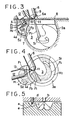
- the reference numeral 1 denotes a piston disposed reciprocatably in and along a cylinder (not shown) of an internal combustion engine
- the numeral 2 denotes a piston top which forms a top surface of the piston 1
- numerals 3 and 4 denote a main combustion chamber and a sub combustion chamber, respectively.
- the main combustion chamber 3 is recessed in the piston top 2 in an axial direction of the piston 1. Further recessed in the piston top 2 is the sub combustion chamber 4 in a radially outward position with respect to the main combustion chamber 3.
- a vertical section of the main combustion chamber 3 passing through an axis O1 of the piston 1 is in the form of a truncated circle. Transverse sections of the main combustion chamber 3 and sub combustion chamber 4 perpendicular to the axial direction of the piston 1 are both circular.
- the sub combustion chamber 4 is shallower than the main combustion chamber 3. And the sub combustion chamber 4 is smaller in capacity than the main combustion chamber 3.
- An inner peripheral wall 3a of the main combustion chamber 3 and an inner peripheral wall 4a of the sub combustion chamber 4 are radially open at the respective portions positioned between both combustion chambers.
- This opening serves as a communication port 7 for connection of both combustion chambers in a contiguous manner.
- the communication port 7 is formed by drawing an axis O2 of the sub combustion chamber 4 close to the axis O1 of the main combustion chamber 3.
- the degree of lap of the sub combustion chamber 4 with respect to the main combustion chamber 3 increases with increase of the approach, and the opening area of the communication port 7 is determined according to the said degree of lap.
- the sub combustion chamber 4 is formed contiguously on an upper side of the main combustion 3, and rotating currents of air for combustion are supplied into the combustion chambers 3 and 4 to form independent swirls S1 and S2 in the chambers 3 and 4, respectively.
- the upper portion of the main combustion chamber 3 extending in the circumferential direction projects radially inwards to an appropriate extent to throttle the upper opening of the main combustion chamber 3 and this throttled portion indicated by the numeral 5 creates a squish current which is forced into the main combustion chamber 3.
- a fuel injecting nozzle means 6 facing the port 7.
- the fuel injecting nozzle means 6 is enclosed in a cylinder head 8 so that a nozzle hole side 6a thereof faces the combustion chamber side.
- the nozzle means 6 is composed principally of a nozzle body 9 enclosed in the cylinder head 8, a needle valve (not shown) which is vertically movable with respect to a valve seat (not shown) provided in the nozzle body 9, a plurality of sub nozzle holes 10 formed through the valve seat, and a main nozzle hole 11 which is opened and closed by a throttle portion of the needle valve.
- the said needle valve is lifted by a hydraulic fuel pressure provided from an injection pump (not shown).
- the fuel injecting nozzle means 6 is a so-called pintaux type nozzle means.
- the sub nozzle holes 10 are each formed extremely small in diameter as compared with the main nozzle hole 11 so that upon opening thereof there is injected a fuel mist F1 having a good ignitability in atomized state into fine particles.
- a fuel mist F2 having a larger particle diameter than the fuel mist F1 and superior in penetratability and diffusibility is injected from the main nozzle hole 1.
- an ignition means 12 constituted by a spark plug or the like is provided within the sub combustion chamber 4 so that an ignition part 13 thereof faces the interior of the sub combustion chamber 4.
- the sub nozzle holes 10 are so formed as to face both upstream and downstream sides of the swirl S2 with the ignition part 13 put therebetween.
- the sub nozzle holes 13 are provided so that they face the vicinity of the ignition part 13 and are directed to the inner wall 4a of the sub ignition chamber 4.
- the main nozzle hole 11 is derected to the inner wall 3a of the main combustion chamber 3 and directed to a downstream side of the swirl S1 which is formed within the main combustion chamber 3.
- the swirls S1 and S2 supplied and formed from swirl ports circle independently in the main and sub combustion chambers 3 and 4, respectively, by virtue of fluid inertia while being compressed.
- the atomized fuel mist F1 of a low cetane number is injected into the sub combustion chamber 4 from the sub nozzle holes 10 of the fuel injecting nozzle means 6. A portion of the thus-injected fuel mist F1 is brought into impingement with the inner wall 4a of the sub combustion chamber 4, while the remaining portion thereof forms a fuel film H1 which is allowed to flow along the inner wall 4a.
- a portion of the injected fuel of low cetane number is evaporated in an instant by a high temperature heat of compressed air because of its small particle size and mixes with air to form a fuel vapor layer F3 which is easy to fire and burn in the sub combustion chamber 4.
- the fuel film H1 is evaporated by the heat of compressed air and the wall heat.
- the fuel vapor layer F3 ignites and is burnt quickly.
- the resulting flame is propagated to the fuel film H1 of the portion flowing and evaporated along the inner wall 4a of the sub combustion chamber 4, so that the fuel film H1 is burnt.
- the ignitability of fuel for the operation of the ignition means 12 can be controlled by adjusting the air-fuel ratio.
- atomized fuel or the fuel mist F2 is injected also from the main nozzle hole 10 toward the inner wall 3a of the main combustion chamber 3 and toward the downstream side of the swirl S1.
- a fuel film H2 and a fuel vapor layer F4 are formed in the main combustion chamber 3 in the same state as in the sub combustion chamber 4.
- a portion of the combustion gas in the sub combustion chamber 4 flows into the main combustion chamber 3, resulting in that flame is propagated to the fuel vapor layer F4 in the main combustion chamber 3, whereby the fuel film H2 in the chamber 3 is ignited and burnt.
- the fuel injecting nozzle means 6 is constructed so that the higher the load, the larger the amount of fuel injected from the main nozzle hole 11, more particularly, a maximum of 90% or more is injected in a high load condition of the engine. Consequently, the above action is attained surely and the fuel vapor layer F4 and fuel film H2 formed by the fuel mist F2 are fired surely by the flame flowing into the main combustion chamber from the sub combustion chamber 4.
- fuels of a high cetane number e.g. gas oil, can also be burnt well according to the present invention.
Landscapes
- Engineering & Computer Science (AREA)
- Chemical & Material Sciences (AREA)
- Combustion & Propulsion (AREA)
- Mechanical Engineering (AREA)
- General Engineering & Computer Science (AREA)
- Combustion Methods Of Internal-Combustion Engines (AREA)
Claims (7)
une chambre de combustion principale (3) creusée axialement dans une partie supérieure (2) d'un piston (1) ;
une chambre de combustion secondaire (4) creusée radialement vers l'extérieur sur un bord latéral supérieur de ladite chambre de combustion principale (3), ladite chambre de combustion secondaire (4) étant contiguë à la dite chambre de combustion principale (3);
un dispositif d'allumage (12) pour accélérer l'allumage, ledit dispositif d'allumage (12) étant placé dans ladite chambre de combustion secondaire (14) à une position proche du point mort haut dudit piston (1) ; et
des moyens d'injection de combustible (6) pour pulvériser et introduire le combustible (F₁, F₂) dans ladite chambre de combustion principale (3) et ladite chambre de combustion secondaire (4) ; caractérisée en ce que
la profondeur de ladite chambre de combustion est réduite radialement vers l'extérieur de sorte qu'il n'y a pas de protubérance ou de chicane à l'interface entre les chambres de combustion principale et secondaire (3, 4).
Applications Claiming Priority (2)
| Application Number | Priority Date | Filing Date | Title |
|---|---|---|---|
| JP60259750A JPS62121827A (ja) | 1985-11-21 | 1985-11-21 | スパ−クアシストデイ−ゼル機関 |
| JP259750/85 | 1985-11-21 |
Publications (3)
| Publication Number | Publication Date |
|---|---|
| EP0227935A2 EP0227935A2 (fr) | 1987-07-08 |
| EP0227935A3 EP0227935A3 (en) | 1988-08-31 |
| EP0227935B1 true EP0227935B1 (fr) | 1991-01-30 |
Family
ID=17338429
Family Applications (1)
| Application Number | Title | Priority Date | Filing Date |
|---|---|---|---|
| EP86116004A Expired - Lifetime EP0227935B1 (fr) | 1985-11-21 | 1986-11-18 | Chambre de combustion pour moteur à combustion interne |
Country Status (6)
| Country | Link |
|---|---|
| US (1) | US4852525A (fr) |
| EP (1) | EP0227935B1 (fr) |
| JP (1) | JPS62121827A (fr) |
| CN (1) | CN1008648B (fr) |
| AU (1) | AU598210B2 (fr) |
| DE (1) | DE3677356D1 (fr) |
Families Citing this family (26)
| Publication number | Priority date | Publication date | Assignee | Title |
|---|---|---|---|---|
| AU586595B2 (en) * | 1985-11-30 | 1989-07-13 | Isuzu Motors Limited | Combustion chamber arrangement for an internal combustion engine |
| JPS63195375A (ja) * | 1987-02-09 | 1988-08-12 | Hino Motors Ltd | アルコ−ルエンジン |
| JPS63306223A (ja) * | 1987-12-25 | 1988-12-14 | Isuzu Motors Ltd | 内燃機関 |
| US4958604A (en) * | 1988-02-10 | 1990-09-25 | Toyota Jidosha Kabushiki Kaisha | Direct fuel injection type spark ignition internal combustion engine |
| DE3943816C2 (de) * | 1988-02-10 | 2001-01-25 | Toyota Motor Co Ltd | Otto-Brennkraftmaschine mit direkter Kraftstoffeinspritzung |
| JP2600275B2 (ja) * | 1988-04-25 | 1997-04-16 | トヨタ自動車株式会社 | 燃料噴射弁 |
| US5058549A (en) * | 1988-02-26 | 1991-10-22 | Toyota Jidosha Kabushiki Kaisha | Fuel swirl generation type fuel injection valve and direct fuel injection type spark ignition internal combustion engine |
| US4974565A (en) * | 1988-02-26 | 1990-12-04 | Toyota Jidosha Kabushiki Kaisha | Fuel swirl generation type fuel injection valve and direct fuel injection type spark ignition internal combustion engine mounted with the fuel injection valve |
| US4898135A (en) * | 1989-02-16 | 1990-02-06 | Sonex Research, Inc. | Piston and process for achieving controlled ignition and combustion of hydrocarbon fuels in internal combustion engines by generation and management of fuel radical species |
| US5144924A (en) * | 1989-12-04 | 1992-09-08 | Oy Wartsila Diesel International Ltd. | Internal combustion engne, and method for achieving ignition of fuel in an internal combustion engine |
| JPH0552145A (ja) * | 1990-12-19 | 1993-03-02 | Toyota Motor Corp | 内燃機関の制御装置 |
| DE59207958D1 (de) * | 1992-11-26 | 1997-03-06 | Avl Verbrennungskraft Messtech | Fremdgezündete Brennkraftmaschine mit einem im Kolben zugeordneten Brennraum |
| JPH07189875A (ja) * | 1993-12-28 | 1995-07-28 | Yamaha Motor Co Ltd | 2サイクルエンジンの燃料噴射装置 |
| DE4441092A1 (de) * | 1994-11-18 | 1996-05-23 | Bosch Gmbh Robert | Ventil zur Einbringung von Kraftstoff oder Kraftstoff-Luft-Gemisch |
| US5787857A (en) * | 1995-12-13 | 1998-08-04 | Simons; Sylvan | Fuel injected internal combustion engine |
| AT3135U1 (de) * | 1998-06-18 | 1999-10-25 | Avl List Gmbh | Verfahren zum betreiben einer mit sowohl fremd-, als auch selbstzündbarem kraftstoff, insbesondere benzin betriebenen brennkraftmaschine |
| US6386175B2 (en) | 1999-03-05 | 2002-05-14 | Ford Global Technologies, Inc. | Fuel injection |
| JP2003512554A (ja) * | 1999-10-18 | 2003-04-02 | オービタル、エンジン、カンパニー(オーストラリア)、プロプライエタリ、リミテッド | 内燃機関における燃料の直接噴射 |
| JP4032690B2 (ja) * | 2001-10-09 | 2008-01-16 | 株式会社日立製作所 | 筒内噴射ガソリンエンジン |
| CN1320261C (zh) * | 2005-02-07 | 2007-06-06 | 大连理工大学 | 活塞顶涡流室燃烧系统 |
| DE102015202361A1 (de) * | 2015-02-10 | 2016-08-11 | Fev Gmbh | Hubkolben-Brennkraftmaschine |
| BR112018009517B1 (pt) * | 2015-11-10 | 2022-09-27 | Nissan Motor Co., Ltd | Método de controle e dispositivo de controle de motor de combustão interna |
| CN107631880B (zh) * | 2017-08-31 | 2019-09-06 | 北京理工大学 | 基于喷雾燃烧引燃的附壁油膜燃烧实验装置和方法 |
| JP6899409B2 (ja) * | 2019-04-19 | 2021-07-07 | 日本特殊陶業株式会社 | スパークプラグ |
| CN112879148B (zh) * | 2021-01-25 | 2022-11-08 | 华中科技大学 | 一种适用于高功率密度柴油机的非对称燃烧室系统 |
| IL316881A (en) | 2022-05-09 | 2025-01-01 | Geberth John | Variable orifice fuel injection nozzle |
Family Cites Families (14)
| Publication number | Priority date | Publication date | Assignee | Title |
|---|---|---|---|---|
| US3125079A (en) * | 1964-03-17 | Multi-purpose internal combustion engine | ||
| GB802118A (en) * | 1956-02-10 | 1958-10-01 | Daimler Benz Ag | Improvements relating to an injection-type internal combustion engine |
| US2881743A (en) * | 1956-12-20 | 1959-04-14 | Ricardo & Co Engineers | Internal combustion engines of the liquid fuel injection compression ignition type |
| US3144008A (en) * | 1961-12-22 | 1964-08-11 | List Hans | Internal combustion engine with compression ignition |
| DE1576001A1 (de) * | 1967-01-14 | 1970-05-21 | Daimler Benz Ag | Fremdgezuendete Einspritzbrennkraftmaschine mit Schichtladung |
| DE1576008B2 (de) * | 1967-10-05 | 1976-07-01 | Daimler-Benz Ag, 7000 Stuttgart | Luftverdichtende einspritzbrennkraftmaschine mit fremdzuendung und gueteregelung |
| DE2826602C2 (de) * | 1978-06-19 | 1982-07-15 | M.A.N. Maschinenfabrik Augsburg-Nürnberg AG, 8500 Nürnberg | Luftverdichtende, direkteinspritzende Brennkraftmaschine |
| JPS5741417A (en) * | 1980-08-21 | 1982-03-08 | Nissan Motor Co Ltd | Combustion chamber of internal combustion engine |
| JPS57148019A (en) * | 1981-03-09 | 1982-09-13 | Mazda Motor Corp | Fuel injector for diesel engine |
| JPS5848710A (ja) * | 1981-09-14 | 1983-03-22 | Toyota Motor Corp | デイ−ゼルエンジン |
| JPS59221419A (ja) * | 1983-05-30 | 1984-12-13 | Isuzu Motors Ltd | 渦流燃焼室式デイ−ゼル機関 |
| JPS61167116A (ja) * | 1985-01-18 | 1986-07-28 | Nissan Motor Co Ltd | 補助点火式デイ−ゼルエンジン |
| US4709672A (en) * | 1985-05-21 | 1987-12-01 | Isuzu Motors Limited | Combustion chamber for an internal-combustion engine |
| JPH063134B2 (ja) * | 1985-12-10 | 1994-01-12 | いすゞ自動車株式会社 | スパークアシストデイーゼル機関の燃焼室 |
-
1985
- 1985-11-21 JP JP60259750A patent/JPS62121827A/ja active Pending
-
1986
- 1986-11-18 EP EP86116004A patent/EP0227935B1/fr not_active Expired - Lifetime
- 1986-11-18 DE DE8686116004T patent/DE3677356D1/de not_active Expired - Fee Related
- 1986-11-19 US US06/932,804 patent/US4852525A/en not_active Expired - Fee Related
- 1986-11-20 AU AU65529/86A patent/AU598210B2/en not_active Ceased
- 1986-11-21 CN CN86108006A patent/CN1008648B/zh not_active Expired
Also Published As
| Publication number | Publication date |
|---|---|
| EP0227935A2 (fr) | 1987-07-08 |
| EP0227935A3 (en) | 1988-08-31 |
| CN1008648B (zh) | 1990-07-04 |
| CN86108006A (zh) | 1987-07-22 |
| AU598210B2 (en) | 1990-06-21 |
| JPS62121827A (ja) | 1987-06-03 |
| DE3677356D1 (de) | 1991-03-07 |
| AU6552986A (en) | 1987-05-28 |
| US4852525A (en) | 1989-08-01 |
Similar Documents
| Publication | Publication Date | Title |
|---|---|---|
| US4852525A (en) | Combustion chamber in internal combustion engine | |
| US4125094A (en) | Internal combustion engine with an auxiliary combustion chamber | |
| US4742804A (en) | Spark-ignition engine | |
| EP0205000B1 (fr) | Chambre de combustion pour moteur à combustion interne | |
| US4712525A (en) | Combustion chamber of internal combustion engine | |
| US4178903A (en) | Internal combustion engine with an auxiliary combustion chamber | |
| EP0237065B1 (fr) | Chambre de combustion pour moteurs à combustion interne | |
| EP0225637B1 (fr) | Chambre de combustion pour moteur à combustion interne | |
| US4116234A (en) | Internal combustion engine with an auxiliary combustion chamber | |
| US4784097A (en) | Combustion chamber for internal combustion engine | |
| JPS62139919A (ja) | 内燃機関の燃焼室 | |
| US4114569A (en) | Internal combustion engine with an auxiliary combustion chamber | |
| JPS61265322A (ja) | 直噴式ディーゼルエンジン燃焼室 | |
| US4178889A (en) | Internal combustion engine | |
| JPS6189919A (ja) | 直噴式デイ−ゼルエンジン燃焼室 | |
| WO2024201933A1 (fr) | Moteur à combustion interne avec chambre de combustion auxiliaire | |
| JPH063137B2 (ja) | 内燃機関の燃焼室 | |
| JP2521914B2 (ja) | 内燃機関 | |
| JPS62153515A (ja) | スパークアシストデイーゼル機関の燃焼室 | |
| JPH0621562B2 (ja) | 内燃機関の燃焼室 | |
| JPS6355321A (ja) | 内燃機関の燃焼室 | |
| JPS62276214A (ja) | 内燃機関の燃焼室 | |
| JPS62153514A (ja) | 内燃機関の燃焼室 | |
| JPS587811B2 (ja) | 内燃機関の気体噴射装置 | |
| JPS62129515A (ja) | 直噴式デイーゼルエンジンの燃焼室 |
Legal Events
| Date | Code | Title | Description |
|---|---|---|---|
| PUAI | Public reference made under article 153(3) epc to a published international application that has entered the european phase |
Free format text: ORIGINAL CODE: 0009012 |
|
| AK | Designated contracting states |
Kind code of ref document: A2 Designated state(s): DE FR GB IT SE |
|
| PUAL | Search report despatched |
Free format text: ORIGINAL CODE: 0009013 |
|
| AK | Designated contracting states |
Kind code of ref document: A3 Designated state(s): DE FR GB IT SE |
|
| 17P | Request for examination filed |
Effective date: 19890119 |
|
| 17Q | First examination report despatched |
Effective date: 19890607 |
|
| GRAA | (expected) grant |
Free format text: ORIGINAL CODE: 0009210 |
|
| AK | Designated contracting states |
Kind code of ref document: B1 Designated state(s): DE FR GB IT SE |
|
| ITF | It: translation for a ep patent filed | ||
| REF | Corresponds to: |
Ref document number: 3677356 Country of ref document: DE Date of ref document: 19910307 |
|
| ET | Fr: translation filed | ||
| PLBE | No opposition filed within time limit |
Free format text: ORIGINAL CODE: 0009261 |
|
| STAA | Information on the status of an ep patent application or granted ep patent |
Free format text: STATUS: NO OPPOSITION FILED WITHIN TIME LIMIT |
|
| 26N | No opposition filed | ||
| PGFP | Annual fee paid to national office [announced via postgrant information from national office to epo] |
Ref country code: FR Payment date: 19941027 Year of fee payment: 9 |
|
| PGFP | Annual fee paid to national office [announced via postgrant information from national office to epo] |
Ref country code: DE Payment date: 19941107 Year of fee payment: 9 |
|
| PGFP | Annual fee paid to national office [announced via postgrant information from national office to epo] |
Ref country code: GB Payment date: 19941108 Year of fee payment: 9 |
|
| PGFP | Annual fee paid to national office [announced via postgrant information from national office to epo] |
Ref country code: SE Payment date: 19941124 Year of fee payment: 9 |
|
| EAL | Se: european patent in force in sweden |
Ref document number: 86116004.2 |
|
| PG25 | Lapsed in a contracting state [announced via postgrant information from national office to epo] |
Ref country code: GB Effective date: 19951118 |
|
| PG25 | Lapsed in a contracting state [announced via postgrant information from national office to epo] |
Ref country code: SE Effective date: 19951119 |
|
| GBPC | Gb: european patent ceased through non-payment of renewal fee |
Effective date: 19951118 |
|
| PG25 | Lapsed in a contracting state [announced via postgrant information from national office to epo] |
Ref country code: FR Effective date: 19960731 |
|
| PG25 | Lapsed in a contracting state [announced via postgrant information from national office to epo] |
Ref country code: DE Effective date: 19960801 |
|
| EUG | Se: european patent has lapsed |
Ref document number: 86116004.2 |
|
| REG | Reference to a national code |
Ref country code: FR Ref legal event code: ST |
|
| PG25 | Lapsed in a contracting state [announced via postgrant information from national office to epo] |
Ref country code: IT Free format text: LAPSE BECAUSE OF NON-PAYMENT OF DUE FEES;WARNING: LAPSES OF ITALIAN PATENTS WITH EFFECTIVE DATE BEFORE 2007 MAY HAVE OCCURRED AT ANY TIME BEFORE 2007. THE CORRECT EFFECTIVE DATE MAY BE DIFFERENT FROM THE ONE RECORDED. Effective date: 20051118 |