EP0227961B1 - Système de commande par dépression pour un mécanisme d'entraînement des barres de déplacement d'un réacteur à eau pressurisée et sa méthode de fonctionnement - Google Patents
Système de commande par dépression pour un mécanisme d'entraînement des barres de déplacement d'un réacteur à eau pressurisée et sa méthode de fonctionnement Download PDFInfo
- Publication number
- EP0227961B1 EP0227961B1 EP86116540A EP86116540A EP0227961B1 EP 0227961 B1 EP0227961 B1 EP 0227961B1 EP 86116540 A EP86116540 A EP 86116540A EP 86116540 A EP86116540 A EP 86116540A EP 0227961 B1 EP0227961 B1 EP 0227961B1
- Authority
- EP
- European Patent Office
- Prior art keywords
- rod
- drive
- drive means
- selectively
- manifold
- Prior art date
- Legal status (The legal status is an assumption and is not a legal conclusion. Google has not performed a legal analysis and makes no representation as to the accuracy of the status listed.)
- Expired - Lifetime
Links
Images

Classifications
-
- G—PHYSICS
- G21—NUCLEAR PHYSICS; NUCLEAR ENGINEERING
- G21C—NUCLEAR REACTORS
- G21C7/00—Control of nuclear reaction
- G21C7/32—Control of nuclear reaction by varying flow of coolant through the core by adjusting the coolant or moderator temperature
-
- G—PHYSICS
- G21—NUCLEAR PHYSICS; NUCLEAR ENGINEERING
- G21C—NUCLEAR REACTORS
- G21C7/00—Control of nuclear reaction
- G21C7/06—Control of nuclear reaction by application of neutron-absorbing material, i.e. material with absorption cross-section very much in excess of reflection cross-section
- G21C7/08—Control of nuclear reaction by application of neutron-absorbing material, i.e. material with absorption cross-section very much in excess of reflection cross-section by displacement of solid control elements, e.g. control rods
- G21C7/12—Means for moving control elements to desired position
- G21C7/16—Hydraulic or pneumatic drive
-
- G—PHYSICS
- G21—NUCLEAR PHYSICS; NUCLEAR ENGINEERING
- G21C—NUCLEAR REACTORS
- G21C7/00—Control of nuclear reaction
- G21C7/26—Control of nuclear reaction by displacement of the moderator or parts thereof by changing the moderator concentration
-
- Y—GENERAL TAGGING OF NEW TECHNOLOGICAL DEVELOPMENTS; GENERAL TAGGING OF CROSS-SECTIONAL TECHNOLOGIES SPANNING OVER SEVERAL SECTIONS OF THE IPC; TECHNICAL SUBJECTS COVERED BY FORMER USPC CROSS-REFERENCE ART COLLECTIONS [XRACs] AND DIGESTS
- Y02—TECHNOLOGIES OR APPLICATIONS FOR MITIGATION OR ADAPTATION AGAINST CLIMATE CHANGE
- Y02E—REDUCTION OF GREENHOUSE GAS [GHG] EMISSIONS, RELATED TO ENERGY GENERATION, TRANSMISSION OR DISTRIBUTION
- Y02E30/00—Energy generation of nuclear origin
- Y02E30/30—Nuclear fission reactors
Definitions
- This invention relates to pressurized water reactor systems and, more particularly, to a vent system and method of operation for controlling and actuating hydraulically operated displacer rod drive mechanisms for selective positioning of water displacer rods in the reactor vessel.
- control rods which are mounted within the reactor vessel, generally in parallel axial relationship, for axial translational movement in telescoping relationship with the fuel rod assemblies.
- the control rods contain materials known as poisons, which absorb neutrons and thereby lower the neutron flux level within the core. Adjusting the positions of the control rods relative to the respectively associated fuel rod assemblies thereby controls and regulates the reactivity and correspondingly the power output level of the reactor.
- control rods are arranged in clusters, and the rods of each individual cluster are mounted to a common, respectively associated spider.
- Each spider is connected to a respectively associated adjustment mechanism for raising or lowering the associated rod cluster.
- reactor control rod clusters RCC
- WDRC water displacer rod clusters
- a total of over 2800 reactor control rods and water displacer rods are arranged in 185 clusters, each of the rod clusters being mounted to a respectively corresponding spider.
- the lower barrel assembly may be conventional, having mounted therein, in parallel axial relationship, a plurality of fuel rod assemblies which are supported at the lower and upper ends thereof, respectively, by corresponding lower and upper core plates.
- the rod guides are of first and second types, respectively housing therewithin reactor control rod clusters (RCC) and water displacer rod clusters (WDRC); these clusters, as received in telescoping relationship within their respectively associated guides, generally are aligned with respectively associated fuel rod assemblies.
- One of the main objectives of the advanced design, pressurized water reactors to which the present invention is directed, is to achieve a significant improvement in the fuel utilization efficiency, resulting in lower, overall fuel costs. Consistent with this objective the water displacement rodlet clusters (WDRC's) function as a mechanical moderator control, all of the WDRC's being fully inserted into association with the fuel rod assemblies, and thus into the reactor core, when initiating a new fuel cycle. Typically, a fuel cycle is of approximately 18 months, following which the fuel must be replaced.
- the WDRC's are progressively, in groups, withdrawn from the core so as to enable the reactor to maintain the same reactivity level, even though the reactivity level of the fuel rod assemblies is reducing due to dissipation over time.
- the control rod clusters are moved, again in axial translation and thus telescoping relationship relatively to the respectively associated fuel rod assemblies, for control of the reactivity and correspondingly the power output level of the reactor on a continuing basis, for example in response to load demands, in a manner analogous to conventional reactor control operations.
- the calandria includes a lower calandria plate and an upper calandria plate.
- the rod guides are secured in position at the lower and upper ends thereof, respectively, to the upper core plate and the lower calandria plate.
- Within the calandria and extending between the lower and upper plates thereof is mounted a plurality of calandria tubes in parallel axial relationship, respectively aligned with the rod guides.
- Flow holes are provided in remaining portions of the calandria plates, intermediate the calandria tubes, through which passes the reactor core outlet flow as it exits from its upward passage through the inner barrel assembly.
- the core outlet flow, or a major portion thereof, turns from the axial flow direction to a radial direction for passage through radially outwardly oriented outlet nozzles which are in fluid communication with the calandria.
- the calandria tubes are joined to corresponding flow shrouds which extend to a predetermined elevation within the head, and which in turn are connected to corresponding head extensions which pass through the structural wall of the head and carry, on their free ends at the exterior of and vertically above the head, corresponding adjustment mechanisms, as above noted.
- the adjustment mechanisms have corresponding control shafts, or drive rods, which extend through the respective head extensions, flow shrouds, and calandria tubes and are connected to the respectively associated spiders mounting the clusters of RCC rods and WDRC rods, and serve to adjust their elevational positions within the inner barrel assembly and, correspondingly, the level to which the rods are lowered into the lower barrel assembly and thus into association with the fuel rod assemblies therein, thereby to control the activity within the core.
- each WDRC is approximately 320 to 360 kg in weight
- each group of four (4) such clusters presents a combined weight of in the range of from 1,280 to 1,440 kg, requiring that a drive mechanism and associated connecting structure for each group of four clusters have substantial strength and durability, and afford a substantial driving force.
- the CRDM's of well known, electromechanical type associated with corresponding clusters of RCC's were mounted in generally parallel axial relationship, vertically above the dome or head of the vessel and extended in sealed relationship through the head for connection by suitable drive rods to the associated RCC's, and provided for selectively controlled gradual raising and lowering of the RCC's for moderating the reactor energy level, or for rapidly lowering same in the case of shutdown requirements.
- a substitute DRDM which utilizes a hydraulically operated piston which is attached through a corresponding drive rod to each group of associated WDRC's, and which mechanism satisfies the spacing limitations, permitting mounting thereof above the head or dome of the vessel in conjunction with the conventional CRDM's.
- An example of such a hydraulically operated drive mechanism for a WDRC is shown in U.S. Patent No. 4,439,054 - Veronesi, issued March 27, 1984 and assigned to the common assignee hereof.
- a pressurized water reactor system including a pressure vessel having provided therein, at successively higher elevations, a lower barrel assembly for receiving fuel rod assemblies therein in parallel axial relationship, an inner barrel assembly for receiving clusters of rods mounted in parallel axial relationship for selectively controlled, axial movement in telescoping relationship with the fuel rod assemblies between a fully inserted position within the lower barrel assembly and a fully withdrawn position within the inner barrel assembly, and a head assembly for containing the pressurized reactor coolant fluid within the vessel, and a hydraulic rod drive arrangement including a vent system for selectively driving the rod clusters between the fully withdrawn and fully inserted positions, a plurality of drive rods respectively connected to said plurality of rod clusters and movable axially therewith through a path of travel corresponding to the movement of the respective rod clusters between the fully withdrawn (positions 3-4) and the fully inserted (position 1) positions thereof; and a plurality of drive means disposed in parallel axial relationship on and extending in sealed relationship through
- the pressure within the vessel head produces a pressure differential within the selected hydraulic mechanisms for withdrawing the corresponding WDRC's.
- the corresponding valves are closed and the pressure differential across the hydraulic mechanisms dissipates, due to a designed rate of leakage past the piston rings therein.
- the WDRC's drop, or descend, by force of gravity, automatically engaging the mechanical latches within the DRDM's which then lock the WDRC's in their withdrawn, parked positions.
- Insertion of one or more WDRC groups into the core from a fully withdrawn and locked position is achieved by initially establishing the valve actuation of condition (I) for the withdrawal operation for a limited interval, sufficent to permit the hydraulic mechanisms to advance upwardly and release the mechanical latches, following which, condition (II) is initiated, in which a further valve is opened to communicate pressure from a head vent of the vessel to the respective hydraulic mechanisms (DRDM's) of the selected group or groups, thereby equalizing the pressure across the corresponding pistons and allowing the WDRC's of each group to descend, or fall, into the core under the force of gravity.
- condition (II) is initiated, in which a further valve is opened to communicate pressure from a head vent of the vessel to the respective hydraulic mechanisms (DRDM's) of the selected group or groups, thereby equalizing the pressure across the corresponding pistons and allowing the WDRC's of each group to descend, or fall, into the core under the force of gravity.
- the withdrawal using bypass, of condition (III) of the vent system accommodates certain abnormal operating conditions, such as when a drive rod is stuck or a set of high leakage piston rings fails to seat properly, which in turn may prevent one or more WDRC clusters from being withdrawn under the normal withdrawal procedure of condition (I).
- the bypass mode serves to bypass the previously noted, common orifice, thereby increasing the pressure drop across the DRDM piston rings by several hundred pounds per square inch (psi), the increased pressure differential thus imposed being sufficient to seat any malfunctioning piston ring and raise the WDRC group to the desired, fully withdrawn position.
- vent system of the invention provides a recovery procedure for correcting any missequencing of the drive operations which may occur either due to unexpected impediments, as above described, or as may arise from inadvertent, premature actuation of the valves causing one or more of the individual DRDM's of a given group to be latched in the parked, fully withdrawn position, while others remain in an intermediate position, neither fully withdrawn nor fully inserted.
- vent system of the present invention provides efficient and effective operation, utilizing the available hydraulic driving force of the high pressure within the reactor vessel, while employing a minimum number of selectively actuated conventional valves and flow restricting devices in combination with the noted, hydraulically actuated DRDM's, to afford a system which is safe and versatile in operation, yet low in cost of components and operation.
- a pressurized water reactor 10 comprises a vessel 12 including an upper dome, or head, 12a, cylindrical sidewalls 12b, and a bottom closure 12c.
- the lower barrel assembly 16 comprises a generally cylindrical sidewall 17 affixed at its lower and upper ends to respective lower and upper core plates 18 and 19.
- Fuel rod assemblies 20 are positioned in generally vertically oriented, parallel axial relationship within the lower barrel assembly 16.
- a neutron reflector and shield 21 is mounted interiorly of the cylindrical sidewalls 17, in conventional fashion.
- the inner barrel assembly 24 includes a cylindrical sidewall 26 within which is positioned a plurality of rod guides in closely spaced, parallel axial relationship; for simplicity of illustration, only two such rod guides are shown in Fig. l, namely rod guide 28 housing a cluster of radiation control rods 30 (RCC) and a rod guide 32 housing a cluster of water displacement rods 34 (WDRC).
- Mounting means 36 and 37 are provided at the respective upper and lower ends of the rod guide 28 and, correspondingly, mounting means 38 and 39 are provided at the respective upper and lower ends of the rod guide 32, the lower end mounting means 37 and 39 mounting the respective rod guides 28 and 32 to the upper core plate l9, and the upper mounting means 36 and 38 mounting the respective rod guides 28 and 32 to a calandria assembly 50.
- the calandria assembly 50 includes a lower calandria plate 52, an upper calandria plate 54, and a plurality of parallel axial calandria tubes 56 which are positioned in alignment with corresponding apertures in the lower and upper calandria plates 52 and 54 and to which the calandria tubes 56 are mounted at their respective, opposite ends.
- Calandria extensions 58 project downwardly from the calandria tubes 56 and connect to corresponding mounting means 36 for the upper ends, or tops, of the RCC rod guides 28.
- the upper end mounting means 38 associated with the WDRC rod guides 32, may be interconnected by flexible linkages to the mounting means 36 of the RCC rod guides 28, in accordance with the invention of the pending application, entitled: "FLEXIBLE ROD GUIDE SUPPORT STRUCTURE FOR INNER BARREL ASSEMBLY OF PRESSURIZED WATER REACTOR" --Gillett et al., assigned to the common assignee herewith.
- the WDRC rod guides 32 may be connected independently to the lower calandria plate 52 by the top end support structure of the invention disclosed in the copending application, entitled: "TOP END SUPPORT FOR WATER DISPLACEMENT ROD GUIDES OF PRESSURIZED WATER REACTOR" -- Gillett et al., assigned to the common assignee hereof.
- a plurality of flow shrouds 60 respectively aligned with the calandria tubes 56.
- a corresponding plurality of head extensions 62 is aligned with the plurality of flow shrouds 60, with respective adjacent ends thereof in generally overlapping relationship.
- the head extensions 62 pass through the head or upper wall of the dome l2a and are sealed thereto.
- Control rod cluster (RCC) displacement mechanisms 64 and water displacement rod cluster (WDRC) displacement mechanisms 66 are associated with the respective head extensions 62, flow shrouds 60 and calandria tubes 56 which, in turn, are associated with respective clusters of radiation control rods 30 and water displacement rods 34.
- the RCC displacement mechanisms (CRDM's) 64 may be of well known type, as are and have been employed with conventional reactor vessels. It will be understood that the drive rods which are connected to the respective RCC clusters 30 extend from the top thereof through the corresponding mechanisms 64, projecting upwardly above same as the clusters are raised and progessing in telescoping fashion downwardly through the mechanisms 64 as the clusters 30 are lowered into association with the fuel assemblies 20.
- the displacer mechanisms (DRDM's)66 for the water displacer rod clusters (WDRC's) 34, as employed with the vent system of the present invention, may be in accordance with the disclosure of U.S. Letters Patent 4,439,054 -Veronesi, as before noted.
- the RCC and WDRC displacement mechanisms 64 and 66 connect through corresponding control shafts, or drive rods (not shown in Fig. l), to the respective clusters of radiation control rods and water displacements rods 30 and 34, to control the respective vertical positions thereof and, particularly, selectively to lower and/or raise same through corresponding openings (not shown) provided therefore in the upper core plate l9, telescopingly into or out of surrounding relationship with the respectively associated fuel rod assemblies 20.
- the clusters 30 and 34 have an extent of travel corresponding to the height of the fuel rod assemblies 20, as seen in Fig. l.
- the WDRC's 34 are lowered, or inserted, fully into the lower barrel assembly l6 which contains the core of fuel rod assemblies 20, following each refueling and thus at the initiation of each fuel cycle.
- the WDRC's 32 through their respective drive rods (not shown in Fig. l) and DRDM's 66, then are selectively removed as the excess reactivity is depleted, over the fuel cycle. Typically, this is performed by simultaneously removing a group of four such WDRC's 34 from their fully inserted positions in association with the fuel assemblies 20, to a fully raised position within the corresponding WDRC guide 32 and thus within the inner barrel assembly 24, in a continuous and controlled withdrawal operation.
- Each group of four WDRC's 34 is selected so as to maintain a symmetrical power balance within the reactor core. Typically, all of the WDRC's 34 remain fully inserted in the fuel assemblies 20 for approximately 60% to 70% of the approximately l8 month fuel cycle. Groups thereof then are selectively and successively withdrawn to the fully withdrawn position as the excess reactivity is depleted, so as to maintain a nominal, required level of reactivity which can sustain the desired output power level, under control of the variably adjustable RCC's 30.
- the vent system of the present invention thus serves to provide hydraulic energizing fluid to the DRDM's 66 in accordance with selectively controlling the WDRC raising and lowering functions, as above described.
- the water flow through the vessel l0 proceeds generally from a plurality of inlet nozzles ll, one of which is seen in Fig. l, downwardly through the annular chamber between an outer generally cylindrical surface defined by the cylindrical sidewall l2b of the vessel l2 and an inner generally cylindrical surface defined by the cylindrical sidewall 26 of the inner barrel assembly 24 and the cylindrical sidewall l7 of the lower barrel assembly l6.
- the pressure of the flowing water, or reactor coolant, within the vessel l0 typically is in the range of about l57,7 bars.
- the reactant coolant pressure furthermore is communicated from the DRDM's 66 through respectively associated conduits 80, flow restricting devices 8l, and conduits 82 to a group manifold 84; as shown in part, four DRDM's 66 are connected through respective conduits 82 to each associated group manifold 84.
- a head vent 86 communicates through the dome l2a with this same source of reactant coolant pressure, as a part of the vent sytem of the present invention.
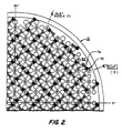
- Fig. 2 is a cross-sectional, schematic bottom planar view of the lower calandria plate 52 at a position, in Fig. l, intermediate the mounting means 36 and 38 for the RCC and WDRC rod guides 28 and 32, respectively, and the plate 52; further, Fig. 2 is on an enlarged scale and represents only a quadrant of the internal structure of the calandria 50, for illustrating diagramatically the dense packing of the arrays of plural control and water displacer rod clusters 30 and 34 within the inner barrel assembly 24.
- Each of the circles labelled “D" represents an aperture, or hole, in the calandria plate 52 through which is received a corresponding DRDM drive rod, associated with a corresponding WDRC cluster; similarly, each of the circles marked “C” corresponds to an aperture in the calandria plate 52 through which is received a corresponding CRDM drive rod, associated with a corresponding RCC cluster 30.
- These apertures C and D provide fluid communication with the corresponding RCC and WDRC calandria tubes 56 and, particularly, through the shrouds and head extensions 62 for communicating the reactant coolant pressure to the DRDM's 66.
- the remaining unlabelled circles in the lower calandria plate 52 in Fig. 2 provide for communicating the reactor coolant flow from the inner barrel assembly 24 to the calandria 50.
- Elements 74 comprise leaf springs which are mounted in oppositely oriented pairs generally in alignment with the diameters of the RCC associated apertures "C,” in an alternating, orthogonally related pattern. The free ends of the springs 74 bear downwardly upon the upper surfaces of the RCC mounting means 36 of a next-adjacent aperture "C,” so as to provide a frictional force opposing lateral displacement thereof and accordingly of the associated rod guide 28, while affording a degree of fiexibility to the axial position of the rod guide.
- springs 74 is one preferred structural mounting means for the RCC guides, in accordance with the disclosure of the above noted, copending application, entitled: "FLEXIBLE ROD GUIDE SUPPORT STRUCTURE FOR INNER BARREL ASSEMBLY OF PRESSURIZED WATER REACTOR,” alternative mounting means may be employed for this purpose and thus the foregoing described structure is not to be deemed limiting in any sense, but merely illustrative.
- Fig. 2 also illustrates the relative locations of the plural inlet and outlet nozzles ll and l3 as seen in Fig. l, it being understood that the quadrant of the vessel shown in the plan view of Fig. l2 is reflected as a mirror image about the 90° axis illustrated thereon and the combined configuration then is reflected about the 0°/l80° axis to establish the full (360°) configuration of the vessel l2.
- a total of four inlet nozzles ll two being equiangularly displaced about each of the 90° and 270° positions
- the RCC clusters and WDRC clusters are disposed in densely packed, interleaved arrays, substantially across the entire cross-sectional area of the inner barrel assembly 24.
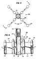
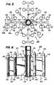
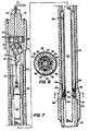
- the RCC and WDRC rod clusters 30 and 34 are supported by corresponding spiders l00 and l20, as illustratively shown in Figs. 3 to 6, in turn connected through corresponding drive rods to the CRDM's 64 and DRDM's 66, an example of the DRDM 66 being shown in Figs. 7 and 8, as hereafter described.
- Figs. 3 and 4 are plan and elevational views of an RCC spider l00, Fig. 3 being schematic in form and Fig. 4 being a partly broken-away, cross-sectional view taken along the line 4-4 in Fig. 3.
- the RCC spider l00 comprises a central hub l02 of generally cylindrical configuration having an upper, interiorally threaded end 103 for connection to a drive rod (not shown) which extends, as before described, upwardly to an RCC adjustment mechanism 64 by which the spider l00 and its associated control rods 30 (Fig. l) may be vertically adjusted in position within and relative to the RCC rod guide 28 and correspondingly relative to the fuel rod assemblies 20, of Fig. l.
- Vane assemblies l06 are secured at the respective inner edges thereof to the hub l02 and extend radially therefrom in quadrature, relative relationship.
- Each vane assembly l06 includes a pair of cylindrically-shaped rod support mounts l08, each thereof having an interior bore l09 including an interiorally threaded portion ll0 into which the upper, correspondingly threaded end of a control rod (not shown) is threadingly engaged so as to be supported by the vane assembly l06 and corresponding hub l02.
- Figs. 5 and 6 illustrate a WDRC spider l20, Fig. 5 being a planar, generally schematic view, and Fig. 6 being an elevational view, partially in cross-section and taken along the line 6-6 in Fig. 5.
- the WDRC spider l20 includes a central hub l22 of generally cylindrical configuration, the upper end l23 being interiorally threaded to receive a drive rod which, as discussed in connection with Fig. l, connects to a corresponding WDRC control mechanism 66.
- First and second types of vane assemblies l26, l27 are connected to the hub l22 in alternating, equiangularly displaced relationship so as to extend radially therefrom.
- the vane assemblies l26 are substantially similar to the RCC vane assemblies l06, as seen in Figs. 3 and 4, and thus include a pair of radially displaced WDRC rod support mounts l28. As best seen in Fig. 5, the vane assemblies l26 are disposed to extend radially from the hub l22 in quadrature relationship, each intermediate an adjacent quadrature-related pair of vane assemblies l06 in the alternating sequence as above described.
- the vane assemblies l27 include integral, transverse vanes l25 extending from the integral radial vane segments l23′ and l24′ as first and second aligned and oppositely oriented pairs l25A and l25B, each thereof carrying a WDRC rod support mount l28 at its extremity.
- Each of the WDRC rod support mounts l28 includes a threaded bore l29 at its lower extremity for receiving, in threaded engagement therein, the top end of a corresponding WDRC rod.
- the vane assemblies l06 and l26 include corresponding first and second planar vane elements ll2, ll4 and l23, l24, respectively, each thereof having longitudinal flanges for connecting the associated vane assemblies l06 and l26 to the respective, RCC spider hub l02 and WDRC spider hub l22.
- This structure is illustrated for the RCC spider l00 in Fig. 4 by the receiving slot lll in the hub l02 and the flange ll5 received therein, and is illustrated for the WDRC spider l20 in Fig. 6 by the receiving slot l2l in the hub l22 and the flange l3l associated with the first planar vane element l23, received therein.
- the second type of vane assembly l27 of the WDRC spider l20 corresponds substantially to the first vane assembly l26 in that it includes first and second planar vane element portions l23′ and l24′ which are integrally formed and extend radially from the hub l22, the first portion l23′ having a longitudinal flange l3l′ received in a corresponding receiving slot l2l′ in the hub l22.
- the assembly l27 furthermore includes first and second pairs l25a and l25b of third planar vane elements l25 integrally formed with and extending transversely from the first and second integral vane element portions l23′ and l24′, the first pair l25a being formed intermediate the portions l23′ and l24′ and the second pair l25b being formed on the outer longitudinal edge of the second vane element portion l24′.
- Each of the elements l25 carries a rod support mount l28 on its outer longitudinal edge.
- the third, or transverse, planar vane elements l25 may include similar flange structures on their outer longitudinal edges for mounting the corresponding rod support mounts l28.
- the innermost planar vane elements ll2, and l23, l23′ preferably are positioned with the respective flanges ll5 and l3l, l3l′ inserted into the corresponding receiving slots lll and l2l, l2l′ of the associated hubs l02 and l20, and then spot welded in place at the upper and lower extremities thereof, as indicated by weld beads. Thereafter, the joints are brazed along the entirety of the lengths thereof.
- the displacer rod drive mechanism (DRDM) 66 receives a drive rod l32 which is connected to a WDRC spider l20.
- the DRDM 66 is shown more fully in the noted U.S. Patent No. 4,439,054.
- the DRDM 66 comprises a substantially cylindrical metal housing l36 which is welded to a head extension 62, which extends through the dome, or head l2a.
- Housing l36 has a cap l38 attached to the top thereof which has a channel l40 therethrough that is connected to conduit 80, as shown in Fig. l.
- a bearing housing l46 is removably disposed within housing l36 and has a plurality of first piston rings l48 attached to the outside thereof near its lower end which extend into contact with the inside of housing l36 for aligning bearing housing l46 within housing l36 but allowing for the removal of bearing housing l46.
- Drive rod l32 is slidably disposed within bearing housing l46 in a manner so as to be able to be moved axially with respect to bearing housing l46 and housing l36 under the influence of the reactor coolant pressure.
- a plurality of second piston rings l50 which may be Inconel, are removably disposed within bearing housing l46 so as to be able to contact drive rod l32.
- Second piston rings l50 provide a mechanism for allowing drive rod l32 to slide within bearing housing l46 while limiting the flow of reactor coolant through bearing housing l46 and housing l36 when the vent system permits fluid flow through conduit 80, the movement of drive rod l32 thus being controlled by the vent system of the invention.
- Second piston rings l50 are arranged so that they may be replaced when bearing housing l46 is removed from housing l36.
- a plurality of roller bearings l52 are disposed on a like number of axles l54 in a manner so as to allow the outer surface of roller bearings l52 to contact the outer surface of drive rod l32 whle allowing the rotation of roller bearings l52.
- four roller bearings l52 may be used so as to align drive rod l32 within bearing housing l46 while aiding in the movement of drive rod l32.
- a plurality of screws l56 corresponding to the number of roller bearings l52 are used to attach holding member l58 to bearing housing l46 so as to hold roller bearings l52 within bearing housing l46 yet allow replacement thereof by removal of screws 156 and holding member 158.
- a second set of roller bearings l60 are disposed at the other end of bearing housing l46 to provide alignment of drive rod l32.
- drive rod l32 has a flexible rod l62 attached to the top end thereof which may be an Inconel rod.
- Flexible rod l62 has a spear-shaped member l64 attached to its top end.
- a hollow cylindrical divider l66 is attached to the lower end of cap l38, in colinear alignment with channel l40.
- Divider l66 defines chambers l68, l69 and l70 in the bottom end of cap l38, each of a size to accommodate the spear member l64.
- the spear-shaped member l64 cooperates with a pivoted latch mechanism l72 in a manner more fully described in U.S. Patent No. 4,439,054.
- the latch l72 is normally spring biased to the slanted, or angularly offset position indicated in Fig. 7, and is mounted for pivotal movement in a clockwise direction in which the right-hand side thereof engages the interior of the wall of housing l36.
- the spear-shaped member moves upwardly along the slanted surface of the latch mechanism l72 as indicated in phantom lines, ultimately passing beyond the upper edge thereof and being received in the first chamber l68, the latch l72 being deflected by that movement to pivot in a clockwise direction and provide clearance for the motion of the spear shaped member l64 and then returning to its initial position by the spring biasing.
- cap l38 functions as a stop to prevent further upward movement of the member l64 and thus the drive rod l32.
- pressure is equalized within the DRDM 66 so as to remove the differential pressure driving the rod l32 upwardly, in a manner to be described, the weight of the rod l32 and attached WDRC cluster causes the same to fall by gravity, the member l64 being received in the first bore l78 of the latch l72 and supported on ledge l82 to stop the downward movement, this action furthermore pivoting latch l72 to a vertically aligned position thus locking, or parking, the rod l32 in its up position.
- the vent system is operated to cause a pressure differential again to be created, acting on the rod l32 so as to drive it upwardly through the bore l78 and into the central chamber l70, upward movement again being halted by the lower surface of cap l68 which acts as a stop on the element l64.
- latch mechanism l72 includes suitable slots in the generally vertically oriented sidewalls thereof through which the flexible rod l62 may pass, to permit movement thereof transversely through the sidewalls defining the bores l78 and l80 of the latch mechanism l72, the slots of course being smaller than the element l64, which travels through the bores l78 and l80, as above described.
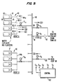
- Fig. 9 is a schematic of the vent system of the invention, in which like elements are identified by like numerals as in Fig. l.
- four WDRC's 34 are joined in a group for common actuation, and thus Fig. 9 illustrates four DRDM's 66 in each of groups A and B, having respective flow restricting devices 8l connected through corresponding conduits 82 (individually designated 82-l, 82-2, 82-3 and 82-4, for group A), a group manifold 84a, through a corresponding group valve V 1a to a system manifold 90.
- Group B is correspondingly connected through a group manifold 84b and valve V 1b to the system manifold 90.
- System manifold 90 schematically indicates connections to plural such groups; as above noted, 22 groups, of four DRDM's 66 each, comprises an exemplary implementation of the system.
- the system manifold 90 further is connected through conduit 9l, system valve V2, and orifice 92 to a conventional reactor coolant drain tank (RCDT) 93, maintained at and thus functioning as a reservoir of normal atmospheric pressure (i.e., 1,05 bar). Additionally, the system manifold is connected through a bypass line 94 and system valve V3 directly to the RCDT 93, thus bypassing the orifice 94. Finally, a conduit 95 connects the head vent 86 (Fig. l) through system valve V4 to the manifold 90.
- RCDT reactor coolant drain tank
- Flow condition I corresponds to a normal withdrawal operation.
- system valve V2 is opened first, to vent the system manifold 90 through orifice 94 to the RCDT 93.
- Group valve V 1a then is opened to vent the DRDM's 66 of group A through the corresponding flow restrictors 8l to the manifold 90.
- the reactor coolant pressure applied to the interior of the DRDM's 66 is about 15,5 x 10⁶ H/m2 (2,250 psi,) whereas a pressure of about 103,4 x 10³ - 206,8 x 10³ H/m2 (15-30 psi) is established at the common orifice 92.
- Group valve V 1a then is closed, following which the pressure differential within the DRDM 66 is dissipated through leakage of the reactor coolant past the piston rings l50. Once equilibrium is reached, the associated WDRC's 34 begin to drop, under the force of gravity, causing the respective engaging latches 72 of the DRDM's 66 to pivot and lock the associated WDRC's 34 in their parked, raised position.
- Flow condition (II) corresponds to an insertion operation for releasing WDRC's 34 which are in the fully withdrawn and locked position, and then inserting same into the lower barrel assembly l6.
- release from the latched position requires that the drive rod l32 first be raised; thus, the flow condition (I) is initiated for a sufficient time to raise the drive rods l32, by briefly opening group valve V 1a and system valve V2.
- System valve V2 then is closed and system valve V4 opened, conveying the system coolant pressure from head vent 86 through conduit 95 to system manifold 90 and through the still opened group valve V 1a , group manifold 84a, and conduits 82 and flow restrictors 8l to the respective channels l40 of the DRDM's 66, thereby equalizing the pressure on the drive rods l32 and permitting the respective WDRC's 34 to fall by force of gravity and be inserted fully into the lower barrel assembly l6.
- the positive pressure equalization step achieved by opening system valve V4 is dictated by the fact that tolerances, temperature differences, and the like can result in inadvertent sealing of, and thus the absence of the intended leakage past, the piston rings l50.
- Flow condition (III) is afforded to accommodate certain unexpected circumstances, such as that of a WDRC 34 which is inadvertently stuck in position, preventing movement thereof in respect to the normal flow condition (I).
- sensors detect such a condition, in which one or more of the WDRC's 34 of a given group, e.g., group A, has or have failed to achieve the withdrawn state.
- the system valve V3 in the bypass conduit 94 is opened (system valve V2 and group valve V1 remaining in the opened condition), bypassing the common orifice 92.
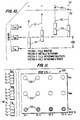
- Fig. l0 is a schematic representation of the movement of a drive rod l32′ and associated WDRC 34′ from position l representing a fully inserted condition, through intermediate positions 2 (indicated by a single such position) during movement, which may be either withdrawal or insertion in this respect, position 3 which is the above-latched position to which the rod and element l64′ must be moved for interacting with the latch mechanism l72 of Fig. 7, and position 4 which is the parked position in which the element l64′ rests on the ledge l82′, the primed numerals corresponding to the structural elements of Fig. 7 in each instance.
- Fig. l0 also illustrates a stop l38′, corresponding to the lower surface of cap l38 in Fig.
- Sensors S IN , S MOV , and S OUT detect the presence of the assemblage of the rod guide l32′ and WDRC 34′, generally illustrated in this instance as detecting the WDRC 34′. Other sensor locations of course may be adopted, where more convenient.
- S IN detects the fully inserted position of WDRC 34′; any interim position of WDRC 34′ is detected by sensor S MOV
- sensor S OUT detects the WDRC l34′ when raised to the over-latch position 3 and also when parked at position 4.
- An independent sensor may be employed to detect position 3, and thus to delineate between positions 3 and 4, if desired, as will be apparent.
- Fig. ll is a schematic illustration of a display 200 associated with the sensors l90 corresponding to a typical group of four WDRC's 34 of a group.
- each of the position sensors S OUT , S MOV and S IN includes four sensors S1 through S4, respectively corresponding to the four WDRC's 34 of the associated group.
- Display 200 correspondingly includes plural indicators 202, which may be conventional lights, including a first row of lights 202 representing the S IN position of each of a group of four WDRC's 34, the vertical columns of indicators 202 thus being designated 34-l through 34-4, and the rows of indicators 202 correspondingly being designated S IN , S MOV and S OUT .
- indicators 202 correspondingly are energized in response to the sensor signals to indicate the positions of the respective WDRC's 34-l through 34-4.
- the indictors will sequence in substantially coordinated fashion from S IN through S MOV to S OUT and remain at the latter during a normal withdrawal and park operation, or will sequence in reverse during a normal insertion operation. Should any missequencing occur, the indicator lights 202 for each WDRC 34 which is out of sequence with the others will correspondingly produce an indication which is inconsistent with the remainder.
- WDRC 34-l may produce an S MOV indication whereas WDRC's 34-2 through 34-4 may produce S OUT indications, the display thus alerting the operator to the circumstance that WDRC 34-l failed to achieve a fully withdrawn and latched state whereas the remainder performed the function as intended.
- condition III in which valve V4 is opened produces an additional pressure differential for driving WDRC 34-l upwardly to the latch position. A successful operation will then result in the proper indication for WDRC 34-l, consistent with the remainder of the group.
- a special circumstance also may occur which again will produce a missequenced display indication on the display panel 200.
- V1 or V2 valves of Fig. 9 are closed prematurely, in that some but not all of the WDRC's 34 of a given group have reached position 3 of Fig. l0, those which have done so will progress to the parked position 4, but the remainder will continue to be in position 2.
- Reestablishing flow condition I to complete withdrawal of the nonlocked WDRC 34 will cause those in the locked position 4 to progress through the unlatching and insertion sequence, while the WDRC 34 which failed to achieve that state may proceed to the fully withdrawn and parked condition 4 -- continuing the missequencing problem.
- Flow condition II is initiated, by opening valve V4 and then, assuming group A to be missequenced, valve V 1a is opened; this circumstance is maintained until the partially withdrawn WDRC 34 (i.e., in position 2) reaches a fully inserted position, i.e., position l of Fig. l0 as indicated by extinction of the S in indicator 202 of Fig. ll for the affected WDRC 34. Valve V4 then is closed, terminating condition II.
- Valve V2 thereupon is opened for a period of approximately 30 seconds, and then closed; since valve V3 is assumed to be closed in this step, and valve V 1a is open, the operation of valve V3 reestablishes flow condition I for a sufficient time to unlatch the WDRC's 34 of the group which theretofore had properly been advanced to the latched and parked, fully withdrawn position.
- the previously malfunctioning WDRC 34 will be driven in the upward, or withdrawal direction as well (e.g., advancing from position l to an intermediate position 2 as illustrated in Fig. l0); however, the time interval for that WDRC 34 to rise to the fully withdrawn position (e.g., position 3 of Fig.
- valve V4 to establish flow condition II thus serves to permit the malfunctioning WDRC 34 to fall by gravity to the fully inserted position l (of Fig.l0), and to permit the WDRC's 34 which had been in the intended, proper sequence to proceed from the fully withdrawn, but now unlatched position, and descend under the force of gravity to join the theretofore missequenced WDRC 34 in the fully inserted position l.
- Flow condition I then is reestablished to withdraw all WDRC's 34 of the group in proper coordinated and sequenced relationship to the fully withdrawn and, then, latched positions 3 and 4 (Fig. l0).
- valves V1 through V4 may readily performed by an operator through the control panel l92 of Fig. 9, in response to the display indications of display panel 200 of Fig. ll.
- the control panel l92 may provide for transmitting respective solenoid actuating signals s 1a , s 1b , ... s2, s3, s4 to the respectively corresponding valves V 1a , V 1b , ... V2, V3, and V4 achieve the foregoing flow conditions, consistent with establishing the desired positions of the WDRC's 34, at all times throughout the fuel cycle.
- the flow restrictors 8l may be of a commercially available type sold under the trade name "LEE AXIAL VISCO JET," having a typical Lohms rating of 680 or 9l0 depending upon the speed of withdrawal required.
- Each of the valves V may comprise direct lift solenoid valves sold by Valcor Engineering Corporation of Springfield, New Jersey under the designation 2-WAY "N" Series 526D.
- the orifice 92 may be formed by drilling a hole through a plate or disk which is then positioned in the vent line either by welding or bolting it between flanges. The size of the hole is selected to attain the proper flow impedance which, in conjunction with the flow restrictor 8l, controls the speed of withdrawal. As an example, a 1,9mm (0.075 inch) diameter hole would give a Lohm rating of approximately l50.
- the vent system of the present invention provides for efficient and effective control of the displacer rod drive mechanisms (DRDM's) 66 and the respectively associated groups of plural symmetrically disposed WDRC's 34, including the capability of correcting for possible malfunctions in the travel of any given WDRC 34 and/or missequenced conditions which may inadvertently occur.
- the vent system moreover is economical and efficient both in its assemblage and operation, utilizing the available pressure within the vessel l2 as the power source, while permitting use of commercially available components to implement the system.
- the vent system moreover affords significant safety factors in its disclosed implementation, while achieving an economic and efficient design.
- the provision of a common manifold 90 enables use of a single orifice 92 and associated valve V2 as well as a single valve V3 affording the bypass function before noted, and a single valve V4 providing connection of the head vent 86 to the common manifold 90.
- These common, or system, elements thus are time shared by the plural groups of DRDM's 66, achieving cost economies.
- this design takes into account safety factors in the operation of a reactor system. Specifically, if two or plural groups of WDRC's 34 were withdrawn simultaneously, power overshoots might occur, presenting a potential danger.
- the present system eliminates that possible concern, through the use of the single, common orifice 92 which limits the total system flow rate to a Lohm value consistent with the desired rate of withdrawal of only a single group of WDRC's 34.
- the resulting flow rate established by the common orifice 92 would be shared in parallel by the DRDM's 66 of the subject groups, greatly reducing the rate of simultaneous withdrawal of the plural groups.
- the system minimizes components, and thus the cost, while affording a significant safety feature as well.
- the provision of individual flow restrictors 8l while not necessary to restrict the flow in view of the provision of the common orifice 92 which theoretically could suffice, alone, for that purpose, affords a safety feature in the event that the common orifice 92 were bypassed, such as by a break in the conduit 9l.
Landscapes
- Physics & Mathematics (AREA)
- Engineering & Computer Science (AREA)
- Chemical & Material Sciences (AREA)
- Chemical Kinetics & Catalysis (AREA)
- Plasma & Fusion (AREA)
- General Engineering & Computer Science (AREA)
- High Energy & Nuclear Physics (AREA)
- Monitoring And Testing Of Nuclear Reactors (AREA)
Claims (12)
- Système (10) de réacteur à eau sous pression comprenant une cuve (12) sous pression dans laquelle se trouve, à des niveaux successivement plus élevés, une enveloppe de coeur inférieure (16) destinée à recevoir des ensembles (20) de barres de combustible dans une dis-position mutuelle axiale et parallèle, une enveloppe de coeur intérieure (24) destinée à recevoir des grappes (34) de barres montées dans une disposition mutuelle axiale parallèle en vue d'un déplacement axial, commandé sélectivement, télescopiquement par rapport aux ensembles (20) de barres de combustible entre une position d'insertion complète à l'intérieur de l'enveloppe de coeur inférieure (16) et une position de retrait complet à l'intérieur de l'enveloppe de coeur intérieure (24), et un couvercle (12a) destiné à contenir le fluide caloporteur sous pression du réacteur à l'intérieur de la cuve (12), et un dispositif hydraulique d'entraînement de barres, y compris un système d'aération, pour entraîner sélectivement les grappes (34) de barres entre la position de retrait complet et la position d'insertion complète, une pluralité de barres d'entraînement (132) reliées respectivement à ladite pluralité de grappes (34) de barres et pouvant se déplacer axialement avec ces dernières sur une course correspondant au déplacement des grappes respectives (34) de barres entre leurs positions de retrait complet (positions 3-4) et d'insertion complète (position 1), et une pluralité de moyens d'entraînement (66) placés dans une disposition mutuelle axiale parallèle sur le couvercle (12c) et s'étendant à travers ce couvercle de façon étanche par rapport à ce dernier et en communication avec le fluide caloporteur sous pression qui s'y trouve, chacun desdits moyens d'entraînement (66) recevant intérieurement, dans une disposition mutuelle étanche, une partie d'extrémité supérieure (132; 162, 164) d'une barre d'entraînement correspondante (132) et permettant un déplacement axial relatif de cette dernière sur ladite course, chaque moyen d'entraînement (66) comportant intérieurement un passage de fuite (entre 136, 146) par l'intermédiaire duquel un écoulement de fuite du fluide caloporteur du réacteur peut passer de manière à établir ainsi un équilibre de pression à l'intérieur dudit moyen d'entraînement (66) en ne produisant pratiquement pas de force nette agissant sur la barre d'entraînement associée (132) et comportant un canal de sortie (140) par l'intermédiaire duquel l'écoulement de fuite du fluide caloporteur du réacteur peut passer jusqu' à l'extérieur du moyen d'entraînement (66) pour créer à l'intérieur de ce dernier une différence de pression établissant une force nette agissant sur la barre d'entraînement (132) de manière à la déplacer vers le haut sur ladite course jusqu' à la position de retrait complet de la grappe associée (34) de barres, et un moyen d'attaque mécanique (172) pouvant être actionné sélectivement pour attaquer une partie d'extrémité supérieure de la barre d'entraînement (132) et pour supporter mécaniquement celle-ci dans sa position précitée de retrait complet, caractérisé par : un réservoir (93) maintenu sensiblement à la pression atmosphérique; des moyens (82, 84a, V1a, [84b, V1b,...], (90, 91, V₂ et 92) associés à ladite pluralité de moyen d'entraînement (66) et audit réservoir (93), pouvant être actionné sélectivement pour raccorder les canaux de sortie correspondants (140) du moyen d'entraînement sélectionné (66) au réservoir (93) de manière à permettre à l'écoulement de fuite dans le moyen d'entraînement sélectionné (66) de passer par le canal de sortie correspondant (140) de chaque moyen d'entraînement sélectionné (66) et à établir une différence de pression à l'intérieur de ce dernier; un raccord d'aération (86) à travers le couvercle (12a) en communication avec le fluide caloporteur sous pression du réacteur à l'intérieur de ce couvercle; et des moyens (82, 84a, V1a , [84b,V1b,...], 90, V4 et 95), associés à ladite pluralité de moyens d'entraînement (86) et au raccord d'aération (86), pouvant être actionnés sélectivement pour raccorder les canaux de sortie correspondants (140) du moyen d'entraînement sélectionné (66) au raccord d'aération (86) afin d'établir rapidement un équilibre de pression à l'intérieur de chaque moyen d'entraînement sélectionné (66).
- Système (10) de réacteur à eau sous pression selon la revendication 1, caractérisé par : un moyen de détection (190) pour détecter sélectivement les grappes (34) de barres correspondantes dans leurs positions d'insertion complète, dans leurs positions intermédiaires entre lesdites positions d'insertion complète de retrait complet et dans leurs positions de retrait complet, et pour produire des signaux de sortie correspondants (SIN, SMOV, SOUT) de détecteur; et une pluralité d'indicateur (202) d'affichage correspondant respectivement à ladite pluralité de grappes (34-1 à 34-4) de barres et comprenant, pour chaque grappe (34) de barres, une pluralité d'indicateurs (SIN' SMOV' SOUT) d'affichage réagissant individuellement et respectivement aux signaux correspondants (SIN, SMOV, SOUT) de détecteurs pour indiquer sélectivement au moins la position d'insertion complète (position 1), une position intermédiaire, et la position de retrait complet de la grappe respectivement correspondante (34-1 à 34-4) de barres.
- Système (10) de réacteur à eau sous pression selon la revendication 1 ou 2, caractérisé par des premier, second ou troisième détecteurs (190 : SIN, SMOV, SOUT) correspondant aux grappes respectives (34-1 à 34-4) de barres pour détecter sélectivement ces dernières dans leur position d'insertion complète, dans une position intermédiaire entre lesdites positions d'insertion complète et de retrait complet, et dans leurs positions de retrait complet, et pour produire des signaux de sortie correspondants (SIN, SMOV, SOUT) de détecteur; et un moyen d'affichage (200) comportant des premier, second, troisième indicateurs d'affichage (202 : SIN, SMOV, SOUT) associés respectivement à chaque grappe (34-1 à 34-4) de barres; et un moyen (190) pour connecter les sorties desdits premier second et troisième détecteurs de chaque grappe (34) de barres audit premier second et troisième indicateur d'affichage (202 : SIN, SM0V, SOUT) respectivement associés desdit moyens d'affichage (200) pour fournir une indication visuelle de la position de chaque grappe (34-1 à 34-4) de barres.
- Système (10) de réacteur à eau sous pression selon la revendication 1, 2 ou 3 comprenant en outre : un moyen de commande (192) pour actionner sélectivement lesdits moyens de connection sélective (82, 84a, V₁a, [84b, V₁b,...] , 90, 91, V₂ et 92; et 82, 84a, V₁a, [ 84b, V₁b,... ] , 90, V₄ et 95) pour commander sélectivement le déplacement de la pluralité de grappes (34) de barres entre lesdites positions de retrait complet (positions 3-4) et d'insertion complète (position 1) de chacune de ces grappes.
- Système (10) de réacteur à eau sous pression selon l'une quelconque des revendications 1 à 4, caractérisé en ce que ladite pluralité de grappes (34) de barres comprend des barres de déplacement d'eau normalement complètement insérées dans l'enveloppe de coeur inférieure (16) au début de chaque cycle de combustible du système (10) de réacteur.
- Système (10) de réacteur à eau sous pression selon l'une quelconque des revendications 1 à 5, dans lequel le poids combiné de chaque barre d'entraînement (132) et de chaque grappe connectée (34) de barres, associée à un moyen d'entraînement donné (66), est suffisant pour permettre à ladite barre d'entraînement (132) et à ladite grappe connectée (34) de barres de tomber sous l'effet de la pesanteur jusqu'à ladite position d'insertion complète (position 1) de la grappe (34) de barres, lorsque la différence de pression à l'intérieur du moyen d'entraînement associé (66) réduit l'équilibre de pression qui y règne, caractérisé en ce que chaque moyen d'entraînement (66) comprend une butée (138) destinée à limiter la course vers le haut de la barre d'entraînement associée (132) lorsqu'elle se déplace jusqu'à ladite position de retrait complet (positions 3-4) de la grappe associée (34) de barres; et le moyen d'attaque mécanique (172) de chaque moyen d'entraînement (66) comprend un moyen pour attaquer mécaniquement l'extrémité supérieure (164) de la barre d'entraînement associée (132) après que la barre d'entraînement (132) a atteint la butée de limitation (138) et que l'équilibre de pression y a été établi, lorsque la barre d'entraînement (132) commence à tomber sous l'effet de la gravité, de manière à supporter ainsi cette barre dans sa position précitée de retrait complet (positions 3-4).
- Système (10) selon l'une quelconque des revendications 1 à 6 dans lequel : chaque moyen d'entraînement (66), lorsqu'il est connecté sélectivement par son canal de sortie (140) au réservoir (93), fait passer un écoulement de fuite à travers son canal de sortie (140) et y établissant la différence de pression précitée pour reproduire une force nette soulevant l'extrémité supérieure (164) de la barre d'entraînement associée (132) en direction de la butée (138) et libérant celle-ci du moyen d'attaque mécanique (172); et chaque moyen d'entraînement (66), lorsqu'il est connecté sélectivement par son canal de sortie (140) audit raccord d'aération (86), établissant un équilibre de pression dans ce dernier pour permettre à la barre d'entraînement correspondante (132) et à la grappe associée (34) de barres de tomber sous l'effet de la gravité jusqu'à sa position d'insertion complète (position 1).
- Système (10) de réacteur à eau sous pression selon l'une quelconque des revendications 1 à 7, comprenant une pluralité de barres d'entraînement (132) et une pluralité de moyens (66) d'entraînement de barres d'entraînement caractérisé par une pluralité de collecteurs-distributeurs (84a, 84b...) de groupes, chaque collecteur-distributeur de groupe étant raccordé en parallèle avec les canaux de sortie (140) d'un groupe respectivement correspondant (A, B, ...) de moyens d'entraînement prédéterminés (66); un système de collecteurs-distributeurs (90); une pluralité de premières vannes (V₁a, V₁b, ...) raccordée respectivement à ladite pluralité de collecteurs-distributeurs (84a, 84b,...) de groupes, chaque première vanne pouvant être actionnée individuellement et sélectivement pour raccorder et cesser de raccorder sélectivement le collecteur-distributeur de groupe (84a, 84b, ...) respectivement correspondant d'un groupe sélectionné (A, B, ...) de moyens d'entraînement (66) au collecteur-distributeur (90) du système; un réservoir (93) maintenu sensiblement à la pression atmosphérique; une seconde vanne (V₂) pour raccorder et cesser de raccorder sélectivement le collecteur-distributeur (90) du système au réservoir (93); chaque première vanne (V₁a, V₁b, ...), quand elle est actionnée sélectivement pour raccorder le collecteur-distributeur de groupe correspondant (84a, 84b, ...) d'un groupe sélectionné de moyens d'entraînement (66) au collecteur-distributeur (90) du système, fonctionnant en coopération avec la seconde vanne (V₂), lorsqu'elle est actionnée pour raccorder le collecteur-distributeur (90) de groupe au réservoir (93), de manière à permettre à un écoulement de fuite de passer par les canaux de sortie (140) du moyen d'entraînement correspondant (66) du groupe sélectionné (A, B, ...) et à établir la différence de pression précitée dans chacun de ces groupes; chaque première vanne (V₁a, V₁b, ...), lorsqu'elle est actionnée sélectivement pour cesser de raccorder le collecteur-distributeur de groupe correspondant (84a, 84b, ...) du collecteur-distributeur (90) du système, bloquant l'écoulement de fuite traversant les canaux de sortie correspondant (140) du moyen d'entraînement (66) du groupe associé (A, B, ...) de manière à établir ainsi un équilibre de pression à l'intérieur de chaque moyen d'entraînement correspondant (66) du groupe sélectionné (A, B, ...); un raccord d'aération (86) sur la cuve (10) en communication avec le fil caloporteur de réacteur sous pression qui s'y trouve; une vanne supplémentaire (V₄) pouvant être actionnée sélectivement pour raccorder et cesser de raccorder sélectivement le raccord d'aération (86) au collecteur-distributeur (90) du système; et chacune desdites premières vannes (V₁a, V₁b, ...) lorsqu'elle est actionnée pour raccorder le collecteur-distributeur de groupe correspondant (84a, 84b, ...) au collecteur-distributeur (90) du système, fonctionnant en coopération avec la vanne supplémentaire (V₄), lorsqu'elle est actionnée pour raccorder le raccord d'aération (86) au collecteur-distributeur (90) de système, pour établir la différence de pression à l'intérieur de chaque moyen d'entraînement correspondant (66) de son groupe sélectionné (A, B, ...) et pour empêcher l'écoulement de fuite par les canaux de sortie respectifs (140) de ce dernier.
- Système (10) de réacteur à eau sous pression selon la revendication 8, caractérisé en ce qu'un orifice (92) est formé entre la seconde vanne (V₂) et le réservoir (93) pour limiter le débit à partir du collecteur-distributeur (90) du système, lorsqu'il est raccordé sélectivement au réservoir (93) par la seconde vanne (V₂) et, de ce fait, le débit de fuite depuis chaque collecteur-distributeur (84a, 84b, ...) de groupe correspondant à un groupe sélectionné (A, B, ...) du moyen d'entraînement (66) et raccordé sélectivement par la première vanne correspondante (V₁a, V₁b, ...) au collecteur-distributeur (90) du système, de manière à limiter ainsi la vitesse de décroissance de la différence de pression existante jusqu'à l'équilibre de pression à l'intérieur du moyen d'entraînement (66) de chaque groupe sélectionné (A, B, ...).
- Système (10) de réacteur à eau sous pression selon la revendication 9, caractérisé en ce que des étrangleurs (81) sont associés au moyen d'entraînement (66) et sont montés entre les canaux de sortie (140) de ces derniers et le collecteur-distributeur de groupe correspondant (84a, 84b, ...), chaque étrangleur (81) limitant l'écoulement de fuite à travers le canal de sortie corresponant (140) du moyen d'entraînement respectif (66).
- Système (10) de réacteur à eau sous pression selon la revendication 10, caractérisé par une quatrième vanne (V₃) montée entre le collecteur-distributeur (90) du système et le réservoir (93) pour raccorder sélectivement le collecteur-distributeur (90) du système au réservoir (93) et pour contourner la seconde vanne (V₂) et l'orifice (92).
- Système (10) selon l'une quelconque des revendications 8 à 11, caractérisé en ce que chaque première vanne (V₁a, V₁b, ...), lorsqu'elle est actionnée sélectivement pour raccorder le collecteur-distributeur de groupe correspondant (84a, 84b, ...) au collecteur-distributeur (90) du système en coopération avec la seconde vanne (V₂), lorsqu'elle est actionnée sélectivement pour raccorder le collecteur-distributeur (90) de groupe au réservoir (93), permet à un écoulement de fuite de passer par le canal de sortie (140) du moyen d'entraînement correspondant (66) du groupe sélectionné (A, B, ...) de ce dernier de manière à établir ainsi la différence de pression précitée pour produire une force afin de soulever l'extrémité supérieure (162, 164) des barres d'entraînement (132) associées au moyen d'entraînement (66) du groupe correspondant (A, B, ...) pour libérer celui-ci du moyen d'attaque mécanique (172); et ladite vanne supplémentaire (V₄), lorsqu'elle est actionnée sélectivement pour raccorder le raccord d'aération (86) au collecteur-distributeur de système, fonctionne en coopération avec la seconde vanne (V₂), lorsqu'elle est actionnée sélectivement pour cesser de raccorder le collecteur-distributeur (90) du système au réservoir (93), afin d'établir un équilibre de pression à l'intérieur de chaque moyen d'entraînement correspondant (66) du groupe sélectionné (A, B, ...) et à permettre ainsi à la grappe de barres correspondante (34) de ce dernier de tomber sous l'effet de la pesanteur jusqu'à leur position d'insertion complète.
Applications Claiming Priority (2)
| Application Number | Priority Date | Filing Date | Title |
|---|---|---|---|
| US806719 | 1985-12-09 | ||
| US06/806,719 US4752433A (en) | 1985-12-09 | 1985-12-09 | Vent system for displacer rod drive mechanism of pressurized water reactor and method of operation |
Publications (3)
| Publication Number | Publication Date |
|---|---|
| EP0227961A2 EP0227961A2 (fr) | 1987-07-08 |
| EP0227961A3 EP0227961A3 (en) | 1988-07-20 |
| EP0227961B1 true EP0227961B1 (fr) | 1991-08-14 |
Family
ID=25194700
Family Applications (1)
| Application Number | Title | Priority Date | Filing Date |
|---|---|---|---|
| EP86116540A Expired - Lifetime EP0227961B1 (fr) | 1985-12-09 | 1986-11-28 | Système de commande par dépression pour un mécanisme d'entraînement des barres de déplacement d'un réacteur à eau pressurisée et sa méthode de fonctionnement |
Country Status (4)
| Country | Link |
|---|---|
| US (1) | US4752433A (fr) |
| EP (1) | EP0227961B1 (fr) |
| JP (1) | JPH083545B2 (fr) |
| KR (1) | KR870006584A (fr) |
Families Citing this family (12)
| Publication number | Priority date | Publication date | Assignee | Title |
|---|---|---|---|---|
| EP0266591B1 (fr) * | 1986-11-03 | 1992-03-11 | Westinghouse Electric Corporation | Supports latéraux chargés élastiquement pour des tubes de guidage de barres de contrôle encastrés d'un côté d'un réacteur à eau pressurisée |
| US4978494A (en) * | 1988-04-01 | 1990-12-18 | Westinghouse Electric Corp. | Hydraulic lock for displacer rod drive mechanism (DRDM) and method of operation |
| US5006301A (en) * | 1989-03-22 | 1991-04-09 | Joyner Engineers And Trainers, Inc. | Method and apparatus for control rod drop monitoring |
| US6795518B1 (en) * | 2001-03-09 | 2004-09-21 | Westinghouse Electric Company Llc | Integral PWR with diverse emergency cooling and method of operating same |
| US8929505B2 (en) * | 2009-08-28 | 2015-01-06 | Terrapower, Llc | Nuclear fission reactor, vented nuclear fission fuel module, methods therefor and a vented nuclear fission fuel module system |
| US9269462B2 (en) * | 2009-08-28 | 2016-02-23 | Terrapower, Llc | Nuclear fission reactor, a vented nuclear fission fuel module, methods therefor and a vented nuclear fission fuel module system |
| US8488734B2 (en) * | 2009-08-28 | 2013-07-16 | The Invention Science Fund I, Llc | Nuclear fission reactor, a vented nuclear fission fuel module, methods therefor and a vented nuclear fission fuel module system |
| US20110150167A1 (en) * | 2009-08-28 | 2011-06-23 | Searete Llc, A Limited Liability Corporation Of The State Of Delaware | Nuclear fission reactor, a vented nuclear fission fuel module, methods therefor and a vented nuclear fission fuel module system |
| US8712005B2 (en) * | 2009-08-28 | 2014-04-29 | Invention Science Fund I, Llc | Nuclear fission reactor, a vented nuclear fission fuel module, methods therefor and a vented nuclear fission fuel module system |
| US8953732B2 (en) | 2010-12-09 | 2015-02-10 | Westinghouse Electric Company Llc | Nuclear reactor internal hydraulic control rod drive mechanism assembly |
| US8873695B2 (en) * | 2011-01-06 | 2014-10-28 | Ge-Hitachi Nuclear Energy Americas Llc | Reactor pressure vessel head vents and methods of using the same |
| JP2014228482A (ja) * | 2013-05-24 | 2014-12-08 | 株式会社東芝 | 制御棒駆動制御装置及び制御棒駆動制御方法 |
Family Cites Families (13)
| Publication number | Priority date | Publication date | Assignee | Title |
|---|---|---|---|---|
| US3957577A (en) * | 1955-06-23 | 1976-05-18 | The United States Of America As Represented By The United States Energy Research And Development Administration | Hydraulic control rod |
| DE2128213A1 (de) * | 1971-06-07 | 1973-01-04 | Licentia Gmbh | Steuerstabantrieb fuer kernreaktoren |
| DE2157067A1 (de) * | 1971-11-17 | 1973-05-24 | Siemens Ag | Kernreaktor |
| BE794342A (fr) * | 1972-01-21 | 1973-07-19 | Westinghouse Electric Corp | Reacteur nucleaire a mecanismes a barre de commande |
| US3855059A (en) * | 1972-05-11 | 1974-12-17 | M Groves | Hydraulic system for nuclear reactors with hydraulically driven control rods |
| US3989589A (en) * | 1973-06-06 | 1976-11-02 | Westinghouse Electric Corporation | Hydraulic drive for control rods |
| US3919043A (en) * | 1973-10-17 | 1975-11-11 | Westinghouse Electric Corp | Digital nuclear reactor control rod position indiction system |
| US4030972A (en) * | 1974-04-22 | 1977-06-21 | Combustion Engineering, Inc. | Fluidly driven control rod |
| JPS5247116A (en) * | 1975-10-11 | 1977-04-14 | Sugito Yamamoto | Supercharging internal combustion engine making use of inertia of a pi ston |
| ZA818395B (en) * | 1980-12-16 | 1983-07-27 | Westinghouse Electric Corp | Spectral shift reactor |
| US4550941A (en) * | 1980-12-16 | 1985-11-05 | Westinghouse Electric Corp. | Hydraulic drive mechanism |
| US4439054A (en) * | 1980-12-16 | 1984-03-27 | Westinghouse Electric Corp. | Latching mechanism |
| FR2558983B1 (fr) * | 1984-01-30 | 1986-06-20 | Framatome Sa | Dispositif de pilotage du coeur d'un reacteur nucleaire |
-
1985
- 1985-12-09 US US06/806,719 patent/US4752433A/en not_active Expired - Fee Related
-
1986
- 1986-11-28 EP EP86116540A patent/EP0227961B1/fr not_active Expired - Lifetime
- 1986-12-09 KR KR860010527A patent/KR870006584A/ko not_active Withdrawn
- 1986-12-09 JP JP61294624A patent/JPH083545B2/ja not_active Expired - Lifetime
Also Published As
| Publication number | Publication date |
|---|---|
| EP0227961A3 (en) | 1988-07-20 |
| EP0227961A2 (fr) | 1987-07-08 |
| KR870006584A (ko) | 1987-07-13 |
| US4752433A (en) | 1988-06-21 |
| JPH083545B2 (ja) | 1996-01-17 |
| JPS62144092A (ja) | 1987-06-27 |
Similar Documents
| Publication | Publication Date | Title |
|---|---|---|
| US3849257A (en) | Guide structure for control elements | |
| EP0227961A2 (fr) | Système de commande par dépression pour un mécanisme d'entraînement des barres de déplacement d'un réacteur à eau pressurisée et sa méthode de fonctionnement | |
| EP0240335B1 (fr) | Réacteur à eau pressurisée ayant un assemblage de cloison modifié | |
| US4778645A (en) | Pressurized water reactor having disconnectable two-piece drive rod assemblies, and related methods of assembly and maintenance operations | |
| EP2839471B1 (fr) | Élément de transition du tube pour réacteur nucléaire compact | |
| US4904443A (en) | Control rod drive with upward removable drive internals | |
| EP0423547A1 (fr) | Système assurant un support amélioré de guidage, avec limiteur de débit, pour barres de contrôle dans le collecteur supérieur d'un réacteur nucléaire | |
| US3212979A (en) | Core support structure | |
| US3212978A (en) | Nuclear reactor core support structure | |
| US12437886B2 (en) | Control rod remote disconnect mechanism | |
| US3855060A (en) | Bottom actuated reactor control rod devices | |
| US5045275A (en) | Gaseous reactor control system | |
| WO2013158498A1 (fr) | Éléments internes supérieurs suspendus pour réacteur nucléaire compact comprenant une plaque de suspension inférieure | |
| US9887015B2 (en) | Suspended upper internals with tie rod couplings for compact nuclear reactor | |
| US4173511A (en) | Control rod blow out protection system | |
| GB2140606A (en) | Calandria | |
| US9767930B2 (en) | Suspended upper internals for compact nuclear reactor including a mid-hanger plate | |
| JPH0321878B2 (fr) | ||
| US4775506A (en) | Nuclear reactor having control clusters with hydraulic actuation | |
| JPS63186183A (ja) | 加圧水型原子炉 | |
| US4126767A (en) | Bottom actuated reactor control system | |
| EP0172355B1 (fr) | Agencement de distribution à l'intérieur d'un réacteur pour système de réglage à modérateur liquide | |
| US5646970A (en) | Core plate repair using control rod guide tube load transfer collar | |
| JPH06798Y2 (ja) | 炉内計装装置の案内構造 | |
| WO2013158447A1 (fr) | Support latéral pour dispositif de commande des grappes de contrôle |
Legal Events
| Date | Code | Title | Description |
|---|---|---|---|
| PUAI | Public reference made under article 153(3) epc to a published international application that has entered the european phase |
Free format text: ORIGINAL CODE: 0009012 |
|
| AK | Designated contracting states |
Kind code of ref document: A2 Designated state(s): BE CH ES FR GB IT LI |
|
| PUAL | Search report despatched |
Free format text: ORIGINAL CODE: 0009013 |
|
| AK | Designated contracting states |
Kind code of ref document: A3 Designated state(s): BE CH ES FR GB IT LI |
|
| 17P | Request for examination filed |
Effective date: 19881123 |
|
| 17Q | First examination report despatched |
Effective date: 19901002 |
|
| GRAA | (expected) grant |
Free format text: ORIGINAL CODE: 0009210 |
|
| ITF | It: translation for a ep patent filed | ||
| AK | Designated contracting states |
Kind code of ref document: B1 Designated state(s): BE CH ES FR GB IT LI |
|
| PG25 | Lapsed in a contracting state [announced via postgrant information from national office to epo] |
Ref country code: BE Effective date: 19910814 |
|
| ET | Fr: translation filed | ||
| PGFP | Annual fee paid to national office [announced via postgrant information from national office to epo] |
Ref country code: ES Payment date: 19911115 Year of fee payment: 6 |
|
| PG25 | Lapsed in a contracting state [announced via postgrant information from national office to epo] |
Ref country code: ES Free format text: LAPSE BECAUSE OF FAILURE TO SUBMIT A TRANSLATION OF THE DESCRIPTION OR TO PAY THE FEE WITHIN THE PRESCRIBED TIME-LIMIT Effective date: 19911125 |
|
| PGFP | Annual fee paid to national office [announced via postgrant information from national office to epo] |
Ref country code: GB Payment date: 19911126 Year of fee payment: 6 |
|
| PG25 | Lapsed in a contracting state [announced via postgrant information from national office to epo] |
Ref country code: LI Effective date: 19911130 Ref country code: CH Effective date: 19911130 |
|
| PLBE | No opposition filed within time limit |
Free format text: ORIGINAL CODE: 0009261 |
|
| STAA | Information on the status of an ep patent application or granted ep patent |
Free format text: STATUS: NO OPPOSITION FILED WITHIN TIME LIMIT |
|
| REG | Reference to a national code |
Ref country code: CH Ref legal event code: PL |
|
| 26N | No opposition filed | ||
| PGFP | Annual fee paid to national office [announced via postgrant information from national office to epo] |
Ref country code: FR Payment date: 19920921 Year of fee payment: 7 |
|
| PG25 | Lapsed in a contracting state [announced via postgrant information from national office to epo] |
Ref country code: GB Effective date: 19921128 |
|
| GBPC | Gb: european patent ceased through non-payment of renewal fee |
Effective date: 19921128 |
|
| PG25 | Lapsed in a contracting state [announced via postgrant information from national office to epo] |
Ref country code: FR Effective date: 19940729 |
|
| REG | Reference to a national code |
Ref country code: FR Ref legal event code: ST |
|
| PG25 | Lapsed in a contracting state [announced via postgrant information from national office to epo] |
Ref country code: IT Free format text: LAPSE BECAUSE OF NON-PAYMENT OF DUE FEES;WARNING: LAPSES OF ITALIAN PATENTS WITH EFFECTIVE DATE BEFORE 2007 MAY HAVE OCCURRED AT ANY TIME BEFORE 2007. THE CORRECT EFFECTIVE DATE MAY BE DIFFERENT FROM THE ONE RECORDED. Effective date: 20051128 |