EP0228007A2 - Machine-outil et son mode d'action - Google Patents
Machine-outil et son mode d'action Download PDFInfo
- Publication number
- EP0228007A2 EP0228007A2 EP86117350A EP86117350A EP0228007A2 EP 0228007 A2 EP0228007 A2 EP 0228007A2 EP 86117350 A EP86117350 A EP 86117350A EP 86117350 A EP86117350 A EP 86117350A EP 0228007 A2 EP0228007 A2 EP 0228007A2
- Authority
- EP
- European Patent Office
- Prior art keywords
- motor
- clamping
- machine tool
- drive
- tool according
- Prior art date
- Legal status (The legal status is an assumption and is not a legal conclusion. Google has not performed a legal analysis and makes no representation as to the accuracy of the status listed.)
- Granted
Links
Images


Classifications
-
- B—PERFORMING OPERATIONS; TRANSPORTING
- B23—MACHINE TOOLS; METAL-WORKING NOT OTHERWISE PROVIDED FOR
- B23B—TURNING; BORING
- B23B31/00—Chucks; Expansion mandrels; Adaptations thereof for remote control
- B23B31/02—Chucks
- B23B31/24—Chucks characterised by features relating primarily to remote control of the gripping means
- B23B31/28—Chucks characterised by features relating primarily to remote control of the gripping means using electric or magnetic means in the chuck
-
- B—PERFORMING OPERATIONS; TRANSPORTING
- B23—MACHINE TOOLS; METAL-WORKING NOT OTHERWISE PROVIDED FOR
- B23B—TURNING; BORING
- B23B23/00—Tailstocks; Centres
-
- B—PERFORMING OPERATIONS; TRANSPORTING
- B23—MACHINE TOOLS; METAL-WORKING NOT OTHERWISE PROVIDED FOR
- B23B—TURNING; BORING
- B23B31/00—Chucks; Expansion mandrels; Adaptations thereof for remote control
- B23B31/02—Chucks
- B23B31/10—Chucks characterised by the retaining or gripping devices or their immediate operating means
- B23B31/12—Chucks with simultaneously-acting jaws, whether or not also individually adjustable
- B23B31/16—Chucks with simultaneously-acting jaws, whether or not also individually adjustable moving radially
- B23B31/16233—Jaws movement actuated by oblique surfaces of a coaxial control rod
-
- B—PERFORMING OPERATIONS; TRANSPORTING
- B23—MACHINE TOOLS; METAL-WORKING NOT OTHERWISE PROVIDED FOR
- B23B—TURNING; BORING
- B23B2260/00—Details of constructional elements
- B23B2260/062—Electric motors
-
- G—PHYSICS
- G05—CONTROLLING; REGULATING
- G05B—CONTROL OR REGULATING SYSTEMS IN GENERAL; FUNCTIONAL ELEMENTS OF SUCH SYSTEMS; MONITORING OR TESTING ARRANGEMENTS FOR SUCH SYSTEMS OR ELEMENTS
- G05B2219/00—Program-control systems
- G05B2219/30—Nc systems
- G05B2219/34—Director, elements to supervisory
- G05B2219/34244—Multiplex for control only
-
- Y—GENERAL TAGGING OF NEW TECHNOLOGICAL DEVELOPMENTS; GENERAL TAGGING OF CROSS-SECTIONAL TECHNOLOGIES SPANNING OVER SEVERAL SECTIONS OF THE IPC; TECHNICAL SUBJECTS COVERED BY FORMER USPC CROSS-REFERENCE ART COLLECTIONS [XRACs] AND DIGESTS
- Y10—TECHNICAL SUBJECTS COVERED BY FORMER USPC
- Y10T—TECHNICAL SUBJECTS COVERED BY FORMER US CLASSIFICATION
- Y10T279/00—Chucks or sockets
- Y10T279/27—Separate chuck-actuating power source
- Y10T279/275—Self-contained
-
- Y—GENERAL TAGGING OF NEW TECHNOLOGICAL DEVELOPMENTS; GENERAL TAGGING OF CROSS-SECTIONAL TECHNOLOGIES SPANNING OVER SEVERAL SECTIONS OF THE IPC; TECHNICAL SUBJECTS COVERED BY FORMER USPC CROSS-REFERENCE ART COLLECTIONS [XRACs] AND DIGESTS
- Y10—TECHNICAL SUBJECTS COVERED BY FORMER USPC
- Y10T—TECHNICAL SUBJECTS COVERED BY FORMER US CLASSIFICATION
- Y10T408/00—Cutting by use of rotating axially moving tool
- Y10T408/08—Cutting by use of rotating axially moving tool with means to regulate operation by use of templet, tape, card, or other replaceable information supply
-
- Y—GENERAL TAGGING OF NEW TECHNOLOGICAL DEVELOPMENTS; GENERAL TAGGING OF CROSS-SECTIONAL TECHNOLOGIES SPANNING OVER SEVERAL SECTIONS OF THE IPC; TECHNICAL SUBJECTS COVERED BY FORMER USPC CROSS-REFERENCE ART COLLECTIONS [XRACs] AND DIGESTS
- Y10—TECHNICAL SUBJECTS COVERED BY FORMER USPC
- Y10T—TECHNICAL SUBJECTS COVERED BY FORMER US CLASSIFICATION
- Y10T409/00—Gear cutting, milling, or planing
- Y10T409/30—Milling
- Y10T409/309576—Machine frame
- Y10T409/309856—Convertible from lathe
-
- Y—GENERAL TAGGING OF NEW TECHNOLOGICAL DEVELOPMENTS; GENERAL TAGGING OF CROSS-SECTIONAL TECHNOLOGIES SPANNING OVER SEVERAL SECTIONS OF THE IPC; TECHNICAL SUBJECTS COVERED BY FORMER USPC CROSS-REFERENCE ART COLLECTIONS [XRACs] AND DIGESTS
- Y10—TECHNICAL SUBJECTS COVERED BY FORMER USPC
- Y10T—TECHNICAL SUBJECTS COVERED BY FORMER US CLASSIFICATION
- Y10T82/00—Turning
- Y10T82/25—Lathe
- Y10T82/2502—Lathe with program control
-
- Y—GENERAL TAGGING OF NEW TECHNOLOGICAL DEVELOPMENTS; GENERAL TAGGING OF CROSS-SECTIONAL TECHNOLOGIES SPANNING OVER SEVERAL SECTIONS OF THE IPC; TECHNICAL SUBJECTS COVERED BY FORMER USPC CROSS-REFERENCE ART COLLECTIONS [XRACs] AND DIGESTS
- Y10—TECHNICAL SUBJECTS COVERED BY FORMER USPC
- Y10T—TECHNICAL SUBJECTS COVERED BY FORMER US CLASSIFICATION
- Y10T82/00—Turning
- Y10T82/25—Lathe
- Y10T82/2552—Headstock
- Y10T82/2562—Spindle and bearings
-
- Y—GENERAL TAGGING OF NEW TECHNOLOGICAL DEVELOPMENTS; GENERAL TAGGING OF CROSS-SECTIONAL TECHNOLOGIES SPANNING OVER SEVERAL SECTIONS OF THE IPC; TECHNICAL SUBJECTS COVERED BY FORMER USPC CROSS-REFERENCE ART COLLECTIONS [XRACs] AND DIGESTS
- Y10—TECHNICAL SUBJECTS COVERED BY FORMER USPC
- Y10T—TECHNICAL SUBJECTS COVERED BY FORMER US CLASSIFICATION
- Y10T82/00—Turning
- Y10T82/25—Lathe
- Y10T82/2564—Tailstock
-
- Y—GENERAL TAGGING OF NEW TECHNOLOGICAL DEVELOPMENTS; GENERAL TAGGING OF CROSS-SECTIONAL TECHNOLOGIES SPANNING OVER SEVERAL SECTIONS OF THE IPC; TECHNICAL SUBJECTS COVERED BY FORMER USPC CROSS-REFERENCE ART COLLECTIONS [XRACs] AND DIGESTS
- Y10—TECHNICAL SUBJECTS COVERED BY FORMER USPC
- Y10T—TECHNICAL SUBJECTS COVERED BY FORMER US CLASSIFICATION
- Y10T82/00—Turning
- Y10T82/26—Work driver
Definitions
- the invention relates to a machine tool with the features mentioned in the preamble of claim 1. Such a machine is disclosed in DE-PS 33 14 629.
- the machine can be a lathe or a milling machine with an electrical tool clamp or a drilling or grinding machine and the like.
- the pressure force is stored in a disc spring package.
- the object of the present invention is to improve the generic machine tool and to further develop it in such a way that the clamping process is shortened, the size is reduced, the availability of the machine as a whole is improved and the overall manufacturing costs of the machine are reduced.
- control devices with integrated microcomputers which operate according to the principle of " frequency conversion (brochure from AMK” PUMASYN three-phase control drives ”) and, adapted to a corresponding tension drive motor, allow the requirements set out above to be met.
- the invention therefore preferably sees its use of such control devices in order to be able to use the possibility of combining both extremely high torques in the range of low speeds and very high maximum speeds.
- the achievement of the very high torques in relation to the size is based on the The fact that with the current applied to the motor, the values for the magnetizing current component and the values for the torque-generating current component can be optimally metered by the microcomputer in constant adaptation to the engine operating state.
- a starting torque can be achieved which is a factor of 8 to 10 times greater than in a control mode which does not provide for this current component metering, for example when controlled by a contactor or by a control device with phase control.
- the concept according to the invention takes into account the fact that, as a rule, the clamping processes of the machine tools in question take place during the standstill of at least the spindle drive motor, possibly also of additionally provided feed motors, and that these motors are operated with a comfortable control device anyway. If at least one further motor, also a three-phase motor, is now used as this one, this can alternately "use" the same control device as the tensioning motor.
- control device must be modified for this purpose. Its outputs are alternately connected to one or the other motor, as are the inputs to which the actual signal is supplied by the motors; in the simplest case, this is the output signal of an angular position sensor provided on the motor.
- the two motors to be controlled have identical parameters; such parameters must, however, be taken into account for the operation of the control device, and the same applies to the control characteristics, which e.g. is desired differently for a lathe spindle drive than for the clamping drive.
- the outputs and inputs of the control device are switched over, the parameters and control algorithms applicable to the associated motor are also switched over; the same applies to the TARGET and ACTUAL values of the motors.
- the concept according to the invention also affects the design of the mechanical parts of the tensioning unit.
- the stator of the clamping drive motor is arranged in a stationary manner, the rotor rotates with the spindle, and its drive torque is converted into an axial movement for driving clamping jaws by means of a hob screw drive. Since this system is very low-friction, it can also be used to control the tensioning force with the appropriate control of the tension drive motor.
- These electric clamps include an electric motor that can be stationary for clamping tools, for example in milling machines, and is only coupled for the clamping process, but can also be designed to rotate with the spindle in lathes.
- the drive torque of the motor is transferred via a reduction gear and a torque limiter to the nut of a sliding screw drive, which interacts with a pull / push tube.
- the torque limiter is designed as a so-called locking mechanism, in which the spur toothing attached to two different parts can disengage after overcoming an adjustable spring force. By changing the spring force, the tension force applied to the tension / compression tube can be changed.
- the locking mechanism By allowing the locking mechanism to engage and disengage over several teeth after the limit torque has been reached, the torque continuously output by the electric motor is converted into a sequence of torque pulses, thereby increasing the clamping force generated by the sliding screw drive.
- a spring element constructed with disc springs is interposed between the pull / pressure pipe and the clamping device (e.g. lathe chuck) in the bore of the working spindle.
- the achievable lifting speeds are too small and should be at least 20 mm / sec.
- the opening and closing times that depend on this go directly into the unproductive idle times.
- the low lifting speeds are due to the fact that the asynchronous three-phase motors controlled by reversing contactors emit a relatively low torque, so that a relatively high gear ratio is necessary to achieve the necessary clamping forces.
- an increase in the engine speed above 3000 rpm is not possible at a line frequency of 50 Hz, and an increase in the engine output is prohibited because of the construction volume that must be increased, in particular the motor stator rotating with the spindle
- the disadvantages of the sliding screw drive can, however, be alleviated if the threaded surfaces of the nut and / or the spindle which are in engagement with one another are subjected to a surface treatment which reduces the dry friction. It is possible to apply very thin layers of extremely hard and friction-reducing material which are still adherent after the usual metallurgical hardening work steps, and preferably by means of the CVD process to precipitate out of the gas phase.
- the layer materials include e.g. Titanium nitride, but a diamond-like carbon is particularly suitable, as described in the publication "Battellelique" from September 2, 1986 or the work "Inon Beam Deposition of Thin Films of Diamondlike Carbon” by Aisenberg / Chabot in J.Appl. Phys., 42/1971, pp. 2935-2958.
- a sliding screw drive which is improved in terms of the frictional conditions in this way can then be made with a larger diameter, possibly even hollow, without the need for a more powerful tensioning drive motor. Conversely, you could choose a smaller motor even with a small diameter of the drive, or do without a reduction gear. Finally, it is also possible to combine these measures with one another.
- a lathe with a motor MI for the clamping drive and a motor MII for the work spindle drive is assumed as an example.
- Each motor is equipped with a rotary encoder, which e.g. provides one output pulse per degree of rotation. The speed of rotation is obtained by differentiating by time, and the rotational acceleration by differentiating again.
- the required motor parameters e.g. moment of inertia of the rotor and other fixed data
- the corresponding control algorithms are stored in memories 411 (for motor MI) and 413 (for motor Mll).
- the actual values and the outputs of the memory for the sake of simplicity, the connections are shown as buses — reach a changeover switch 414, so that only the data belonging together can be fed to the controller 415.
- the actual values are also connected to an interface 416, which is in dialogue with a conventional one via a bus 417 CNC machine control stands.
- the control signals from the controller 415 reach a manipulated variable converter or an output stage 418, which converts the supplied mains power, here 380 V mains voltage, in three phases into the required stator currents of the two motors, which, depending on the position of the switch 419, convert one of the motors MI or MII are activated.
- the CNC control also delivers the setpoints via the interface, and the setpoints are also switched using switch 420. All three switches are controlled by the CNC control via the interface.
- a signal is generated by means of a clamping force sensor, which causes a steady reduction in the rotational frequency with a simultaneous increase in the clamping force, in such a way that exactly when the intended clamping force is reached -Value the speed of rotation of the clamping motor assumes a certain prescribed residual value, here the value zero.
- the control device is designed to regulate the speed of the motor to a constant value, the sudden high load leads to one sharp increase in the required current, which can be recorded and evaluated. If, on the other hand, the control device is designed so that the torque delivered is constant, the sudden increase in load leads to a decrease in the speed, which can be detected and evaluated via the corresponding encoder (actual value). In the drawing, the latter case is assumed for the sake of simplicity; for the person skilled in the art it is understood that the controller must additionally apply the output signal of the tension force sensor when working with one (indicated by the dashed line).
- the power requirement for a work spindle drive of a lathe and for its chuck drive are at least approximately comparable in size, so that the dimensioning of the output stage fits both. It should also be pointed out that instead of the chuck drive, or alternately with it, the drive for the tailstock quill can also be actuated with the main spindle drive control device.
- the transfer of the invention to other types of machine is readily apparent to those skilled in the art from the foregoing.
- the duty cycle of the tension drive motor is generally at most 2%, with the maximum output being able to be applied only during a fraction of this time.
- the motor can therefore be made very small without the risk of thermal overload.
- the spindle drive is to be designed for a duty cycle of 100%, so that the motor MII will be significantly larger than the motor MI.
- this can be taken into account by the different parameters applied to the controller, as well as the resulting different control algorithms.
- the switching processes and the corresponding alternating access to the motor parameters, control algorithms, actual values and target values are assigned to the internal computer of the control device; one can alternatively also use the computer - a higher-level CNC control of the overall machine.
- the three-phase motor is preferably designed as a squirrel-cage motor, preferably as an asynchronous motor, because this has advantages in terms of price and construction, in particular if the stator of the tension drive motor is stationary but its rotor rotates with the spindle.
- clamping units with a sliding screw drive are of course preferred for reasons of cost, such clamping units are primarily dealt with below.
- the clamping force F A to be generated is 70,000 N.
- the torque M ds on the sliding screw drive, which is theoretically necessary for operation without any friction, is according to a simplified formula
- the motor specialist recognizes that the fulfillment of both requirements, namely on the one hand for an extremely high torque in a small size and low speed and on the other hand for a very high speed in view of the multipole of the stator to be provided, while at the same time fulfilling the required good control dynamics, a high-quality control device assumes.
- the motor must be influenced with the inclusion of a sensor for the current detection of the actual clamping force value.
- the clamping motor cannot be stopped in such a way that the motor speed is continuously reduced to zero until the specified clamping force is reached.
- it is rather necessary to run at a certain minimum rotational speed until then, when the specified clamping force is reached, the engine is suddenly stopped. This requires high control dynamics of the electric drive.
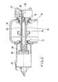
- FIG. 2 shows the headstock 10 with the spindle 14 mounted in roller bearings 12.
- a chuck body 16 At one free end of the spindle there is a chuck body 16 in which a clamping piston 18 is accommodated in an axially displaceable manner; the latter actuates the clamping jaws 22 in a manner known per se.
- the spindle drive takes place via a toothed wheel 24 which, for example, via a toothed belt (not shown) with a spindle drive motor (not shown, but designated in FIG. 1 by "MII”) ), connected is.
- MII spindle drive motor
- the latter carries the rotor 26 of a clamping motor, the stator of which is accommodated in a housing 28 flanged to the headstock 10. (Motor "MI" in Fig. 1)
- a pull / pressure tube 30 Extending through the hollow spindle 14 is a pull / pressure tube 30, which is connected to the tensioning piston 18 at the chuck end, and at the end of the tensioning motor with the screw of a hobbing drive, the nut of which can be rotated relative to the spindle 14 by the tensioning motor.
- the terminal box for the stator power supply is labeled 32.
- Fig. 3 you can see the housing 28 with the stator of the clamping motor, comprising the yoke 40 with the winding 42.
- the rotor formed as a short-circuit rotor includes the core 44 with the short-circuit rings 46. It is clamped on a sleeve 48, the end flange 50 one Spur gear 52 carries; this rotates in front of a stationary inductive transmitter 128, which delivers one pulse per angle of rotation unit; the use of these pulses will be explained later.
- the end flange 50 is screwed to an inner tube 54 coaxial with the sleeve 48, which is supported in roller bearings 56, 58 and has an external toothing 60 at its free end.
- a sleeve 62 is screwed, with which a pipe section 64 is connected; this has an internal toothing 66 at the level of the toothing 60.
- a bushing 68 is screwed, in which the outer rings of the roller bearings 56, 58 are fixed.
- the sleeve 62, the pipe section 64 and the bush 68 are rotatably connected to the spindle 14.
- the components connected to the rotor 44/46 of the tensioning motor that is to say the sleeve 48, the end flange 50 and the inner tube 54, are rotatable relative to this assembly and to the stationary housing 28.
- the component becomes Planet carrier 70 pass through an angle of rotation which depends on the reduction ratio of the planetary gear, formed by the toothing 60, 66 and the pinions 72. This rotation of the planet carrier is transmitted to the nut 74 and through the thread 77 in an axial displacement of the drive screw 78 and the connected components implemented.
- these components comprise a guide tube 80, the free end of which is coupled to a slide 84 by means of a roller bearing 82 in such a way that the slide or by means of a screwed-in cam 86, which runs in an elongated hole 88 of the housing attachment 90, is secured against rotation - is dragged along by the drive screw 78.
- the carriage 84 carries a measuring head 92, which will be discussed later.
- the drive screw 78 On the side of the drive screw 78 facing the spindle 14, the drive screw 78 is connected in a rotationally and axially fixed manner to the tubular connecting piece 94 to the pull / push pipe 30. Its structure is shown in Fig. 4, which will be discussed below.
- the pull / push tube 30 comprises an outer tube 100, connected in a rotationally and axially fixed manner to a stop sleeve 102, into which the tensioning piston 18 is screwed coaxially.
- the outer tube 100 there is the rod 104, on the feed end of which the driver bush 106 is located; disc spring assemblies 108 are arranged between the outer tube and the rod. They are supported on the feed side via a pressure ring 110 on the sleeve 102, which, however, can be displaced from the driving bush 106 in the direction of the tensioning motor with compression of the disc springs if the rod 104 is pulled out of the outer tube (to the left in FIG. 4).
- the plate spring assemblies 108 are supported on a shoulder of the outer tube 100 via a second pressure ring 112.
- this pressure ring can also be displaced into the outer tube 100, the plate springs being compressed when the rod 104 is pushed into the outer tube 100 (to the right in FIG. 4).
- the connecting piece 94 carries a wedge 114 which engages in axial grooves 116 of the outer tube 100 and thus connects the connecting piece 94 and the outer tube 100 to one another in a rotationally fixed manner, but permits relative displacement of the two in both axial directions, in each case with compression of the plate springs, as explained above.
- a pin 120 extends radially through elongated holes 118 of the connecting piece 94 and is connected in a rotationally fixed manner to a sliding piece 122 which is guided axially displaceably in a bore in the connecting piece 94.
- One end of a sensor rod 124 is screwed into the slider, which extends through the drive screw 78 and the guide tube 80 to beyond the roller bearing 82 and carries a sensor head 126 there. With a relative axial displacement of outer tube 100 and rod 104, there is accordingly a relative displacement of sensor head 126 to measuring head 92.
- Sensor head 126 and measuring head 92 interact in such a way that, depending on their mutual distance in the measuring head, an electrical signal (analog or digital) is generated, which is representative of this distance and thus representative of the degree of compression of the plate spring assemblies 108, which serve as a tension force store.
- the lower curve shows the course of the output signal from sensor 92/126 as a function of the angle of rotation of the tensioning motor rotor, which is denoted by ß.
- ß the angle of rotation of the tensioning motor rotor
- the clamping device In the event that e.g. On a drilling and milling machine the clamping device is used to hold interchangeable tools with the same shank diameters, there is no need for a sensor to determine the actual value of the clamping force. Since here during the clamping process - starting from a certain angular position of the clamping motor rotor in the open state of the clamping device - a predetermined clamping force with a deformation of a clamping force storage spring derived therefrom is achieved after the replacement of an associated constant angle of rotation, the control of the clamping motor can be carried out only after measured actual rotation angle value.
- the power requirements for a work spindle drive of a lathe and for its chuck drive are at least approximately comparable in size, so that the dimensioning of the output stage fits both. It should also be pointed out that instead of the chuck drive, or alternately with it, the drive for the tailstock quill can also be actuated with the main spindle drive control device.
- the duty cycle of the tension drive motor is generally at most 2%, with the maximum power being able to be applied only during a fraction of this time.
- the motor can therefore be made very small without the risk of thermal overload.
- the spindle drive is to be designed for a duty cycle of 100%, so that the motor MII will be significantly larger than the motor MI.
- this can be taken into account by the different parameters applied to the controller, as well as the resulting different control algorithms.
- the tensioning motor could rotate the spindle instead of shifting the drive screw, or both.
- the spindle drive motor has a brake that blocks it when the spindle drive is switched off.
- the rotor of the clamping motor will continue to run at the previous speed at least briefly and, depending on this, make the clamping force impermissibly high or even, in the other case, unclamp the workpiece . For this reason, precautions have been taken to mechanically couple the rotor to the spindle when the tensioning motor is switched off.
- stator core 40 of the tensioning motor is extended axially in relation to the rotor core in the direction of the spindle, and in the end region of the stator core, a coupling ring 130 with an end toothing in alignment with a counter toothing 132 on the bush 68 sits on the rotor.
- the coupling ring is open Bolts 134 mounted, which are biased by springs 136 in the direction of gear engagement.
- the control device in its preferred embodiment enables the field-generating current component and the torque-generating current component to be connected separately to the stator winding 42.
- the control algorithm is accordingly designed such that always first the field-generating component is switched on, whereby the coupling ring - as the armature of the stator core, which then acts as a magnet - is released from the toothing, and only then is the torque generated. When switching off, of course, you do the opposite.
- the parallel detection of the angle of rotation, clamping force and braking torque (via the operating parameters of the control unit) enables various monitoring functions to be provided.
- the play between the drive nut and the drive screw is noticeable when the direction of rotation is reversed by a sharp drop in the braking torque, and the associated angle of rotation is then a measure of the "slack" in the slide screw drive and thus a measure of the wear, so that e.g. a warning signal can be triggered if a predetermined limit value is exceeded.
- the level of the braking torque during the idle stroke ⁇ L is a measure of the lubrication state of the screw drive, and here too a warning signal can be generated if a predetermined limit value is exceeded.
- a sliding screw drive is also provided, but in which the friction-reducing coating mentioned at the outset is provided and therefore the threads may be of a larger diameter so that the spindle can be made hollow.
- the clamping motor is stationary with respect to the spindle rotation and its rotor is only coupled to the spindle for the clamping or unclamping process.
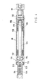
- the pull-pressure tube 152 Located within the spindle 150 is the pull-pressure tube 152, which rotates with the spindle and can be displaced axially relative to the spindle for the purpose of actuating clamping jaws.
- a flange 154 is screwed to the spindle and carries an energy storage assembly 158 via screws 156.
- This assembly includes a support sleeve 160 in which an inner ring 162 is seated.
- a first plate spring 166 is axially supported on the end flange 164 of the inner ring; on its other side, it is clamped by a first intermediate ring 168.
- the support sleeve is fixed.
- the radially outer circumferences of the plate springs 166, 170 are fixed on an outer ring 174 by means of a further clamping ring 176 and an eyebolt 178, screwed into the outer ring 174.
- Pins 180 extend from the outer ring 174 into a slot 182 of the support sleeve 160, so that both are coupled to one another in a rotationally fixed but axially displaceable manner.
- the respective axial position of the outer ring 174 relative to the spindle and thus relative to the headstock 184 is detected by means of a sensor 186 installed in the headstock.
- the outer ring 174 is also connected via a crossed roller bearing 188 to the nut 190 of a slide screw drive, the hollow screw 192 of which is screwed to the pull-pressure pipe 152.
- Axial splines 194 on the outside of the screw 192 couple it in a rotationally fixed but axially displaceable manner to the inner ring 162 of the energy storage assembly.
- the pull-pressure pipe 152 is accordingly axially displaced until it is braked strongly, for example by clamping jaws running onto a workpiece; from then on further rotation of the nut leads to it screwing axially along the screw 192 with axial displacement of the outer ring 174, the disk springs 166, 170 being elastically deformed and storing the tensioning force.
- a motor housing 204 is flanged to the headstock, which receives the stator 206 of a tension drive motor and to which a sleeve 208 is screwed, which extends inward from an end flange 210.
- the rotor 216 of the motor which is fixedly connected to the coupling tube 218, is mounted on it by means of ball bearings 212, 214.
- the ball bearing 212 is slidably seated on the sleeve 208, and the ball bearing 214 is slidably seated in the coupling tube 218.
- a return spring 220 is clamped, which during the spindle rotation, that is to say with the tension drive motor de-energized, the rotor of the latter in the axial position shown holds, defined by the stop ring 222.
- the coupling tube 218 has on its inner end face an end toothing 224 which can be brought into engagement with the end toothing 202 of the coupling ring by axially displacing the coupling tube 218 with compression of the spring 220. This is done by switching on the motor current, which pulls the rotor into the stator. Tra both coupling parts peripheral teeth, which in cooperation with sensors 226 and 228 allow the detection of the angular position, so that the spur teeth are not damaged when engaging.
- the overall arrangement has a central symmetry with respect to the spindle axis, so that only the upper half had to be shown in section.
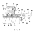
- Fig. 7 shows schematically in axial section the tailstock area of a lathe.
- the machine bed 330 carries in the usual way the straight guide 332 for the tailstock slide 334 with quill 336, whose end facing away from the headstock is supported on a compression spring arrangement 338.
- the tailstock carriage is displaced by means of a roller screw drive, the nut 342 of which is held at 340 and cooperates with the spindle 344 which can be driven to rotate.
- An axial bearing 346 absorbs the reaction forces.
- a coupling 348 a servo motor 350, fastened to the bed 330 by means of a bracket 352 (screws 360), drives the spindle 344 to rotate and thereby displaces the tailstock slide 334.
- the motor is connected to a control device via a multi-conductor cable 354, preferably the same, that is also assigned to the clamping drive and the spindle drive.
- a displacement sensor 362 is also provided. This makes it possible to selectively reach a predetermined clamping karst or a predetermined adjustment path. It goes without saying that according to this scheme, further servo drives can be operated from the same control unit, provided that they cannot be controlled at the same time.
- a friction-reducing coated slide screw drive can be provided instead of the roller screw drive 342/344.
Landscapes
- Engineering & Computer Science (AREA)
- Mechanical Engineering (AREA)
- Gripping On Spindles (AREA)
- Control Of Ac Motors In General (AREA)
Applications Claiming Priority (6)
| Application Number | Priority Date | Filing Date | Title |
|---|---|---|---|
| DE3546252 | 1985-12-28 | ||
| DE3546251 | 1985-12-28 | ||
| DE19853546252 DE3546252A1 (de) | 1985-12-28 | 1985-12-28 | Werkzeugmaschine und deren betriebsverfahren |
| DE3546251 | 1985-12-28 | ||
| DE3630441 | 1986-09-06 | ||
| DE19863630441 DE3630441A1 (de) | 1985-12-28 | 1986-09-06 | Werkzeugmaschine |
Publications (3)
| Publication Number | Publication Date |
|---|---|
| EP0228007A2 true EP0228007A2 (fr) | 1987-07-08 |
| EP0228007A3 EP0228007A3 (en) | 1989-04-26 |
| EP0228007B1 EP0228007B1 (fr) | 1992-04-15 |
Family
ID=27193834
Family Applications (1)
| Application Number | Title | Priority Date | Filing Date |
|---|---|---|---|
| EP86117350A Expired - Lifetime EP0228007B1 (fr) | 1985-12-28 | 1986-12-12 | Machine-outil et son mode d'action |
Country Status (3)
| Country | Link |
|---|---|
| US (1) | US4852434A (fr) |
| EP (1) | EP0228007B1 (fr) |
| DE (1) | DE3684894D1 (fr) |
Cited By (8)
| Publication number | Priority date | Publication date | Assignee | Title |
|---|---|---|---|---|
| DE3727445C1 (en) * | 1986-09-06 | 1988-03-10 | Hubert Dipl-Ing Bald | Arrangement for adjusting the jaws in power-operated chucks |
| DE3901179A1 (de) * | 1988-01-19 | 1989-08-03 | Gedib Ingenieurbuero U Innovat | Spannvorrichtung fuer werkzeugmaschinen |
| EP0343315A3 (fr) * | 1988-05-26 | 1991-07-10 | Hardinge Brothers Inc. | Dispositif de sécurité pour un outil et procédé d'assemblage |
| EP0547388A3 (en) * | 1991-11-20 | 1993-09-08 | Gebr. Heller Maschinenfabrik Gmbh | Chuck for supporting a crankshaft during machining |
| WO2000025966A1 (fr) * | 1998-11-02 | 2000-05-11 | Schroeder Reinhard | Dispositif de serrage d'une broche de machine |
| EP2103368A1 (fr) * | 2008-03-20 | 2009-09-23 | Karl Hiestand | Dispositif de tension pour machines-outils |
| EP2384839A1 (fr) | 2010-05-04 | 2011-11-09 | Karl Hiestand | Dispositif de tension |
| US20170361380A1 (en) * | 2016-06-17 | 2017-12-21 | Baker Hughes Incorporated | Tail stock for a long vertically suspended workpiece that will experience heat expansion |
Families Citing this family (30)
| Publication number | Priority date | Publication date | Assignee | Title |
|---|---|---|---|---|
| US5139246A (en) * | 1989-11-08 | 1992-08-18 | Canon Kabushiki Kaisha | Work clamping apparatus |
| DE4137385C2 (de) * | 1991-11-14 | 1993-11-18 | Hilti Ag | Drehzahlregeleinrichtung für ein handgehaltenes Elektrowerkzeug und Verfahren zu deren Herstellung |
| US5282402A (en) * | 1992-04-14 | 1994-02-01 | Hardinge Brothers, Inc. | Machine tool tailstock |
| US5625267A (en) * | 1995-12-13 | 1997-04-29 | Coburn Optical Industries, Inc. | Constant delay filtering for synchronized motion on multiple axes |
| JP3694573B2 (ja) * | 1997-03-10 | 2005-09-14 | ファナック株式会社 | プレス機械におけるモータトルク制御方法及びプレス機械 |
| DE29809768U1 (de) * | 1998-05-20 | 1999-09-23 | Elektra Beckum Ag, 49716 Meppen | Tragbare Werkzeugmaschine, insbesondere Tischkreissäge |
| DE19824135A1 (de) * | 1998-05-29 | 1999-12-09 | Bosch Gmbh Robert | Förderaggregat für Kraftstoff |
| US6106365A (en) * | 1998-11-06 | 2000-08-22 | Seh America, Inc. | Method and apparatus to control mounting pressure of semiconductor crystals |
| DE19911411A1 (de) * | 1999-03-15 | 2000-09-28 | Boehringer Werkzeugmaschinen | Werkzeugmaschine |
| ATE373528T1 (de) * | 1999-10-13 | 2007-10-15 | Sango Co Ltd | Drückwalzvorrichtung |
| GB0028931D0 (en) * | 2000-11-28 | 2001-01-10 | Pratt Burnerd Internat Ltd | Actuator for workpiece holding device |
| ES2196995B2 (es) * | 2002-02-19 | 2004-11-16 | Danobat, S. Coop. | Contrapunto con control automatico de posicion y fuerza. |
| DE20203501U1 (de) * | 2002-03-05 | 2002-06-27 | Deckel Maho Pfronten GmbH, 87459 Pfronten | Werkzeugmaschine mit Bremseinrichtung für ein Maschinenteil |
| FR2850893B1 (fr) * | 2003-02-11 | 2006-12-08 | Briot Int | Dispositif de meulage de verres ophtalmiques comportant des moyens ameliores de serrage de l'ebauche du verre a meuler |
| WO2005048435A1 (fr) | 2003-11-13 | 2005-05-26 | Sew-Eurodrive Gmbh & Co. Kg | Entrainement compact |
| SG125940A1 (en) * | 2004-03-12 | 2006-10-30 | Seagate Technology Llc | Disc media retainer |
| DE102005021629A1 (de) * | 2005-05-06 | 2006-11-09 | Röhm Gmbh | Bohrvorrichtung |
| US20090255526A1 (en) * | 2005-08-17 | 2009-10-15 | Bsh Bosch Und Siemens Hausgerate Gmbh | Cooking appliance |
| DE102006004375A1 (de) * | 2006-01-31 | 2007-08-02 | BSH Bosch und Siemens Hausgeräte GmbH | Gargerät |
| DE102007032416A1 (de) * | 2007-07-12 | 2009-01-15 | Aradex Ag | Verfahren zur Betätigung einer Spannvorrichtung und Spannsystem zur Durchführung des Verfahrens |
| US8459659B2 (en) * | 2007-12-19 | 2013-06-11 | Illinois Tool Works Inc. | Hybrid lathe chuck |
| CN102131469B (zh) | 2008-06-26 | 2013-07-17 | W·安德森 | 深度可控且可测的医疗驱动设备及使用方法 |
| US8894654B2 (en) * | 2010-03-31 | 2014-11-25 | Smart Medical Devices, Inc. | Depth controllable and measurable medical driver devices and methods of use |
| DE102011003004B3 (de) * | 2011-01-21 | 2012-02-16 | Mag Ias Gmbh | Verfahren und Werkzeugmaschine zum Bearbeiten und Härten von metallischen Werkstücken |
| EP2965845B1 (fr) * | 2013-02-01 | 2017-11-29 | Gildemeister Drehmaschinen GmbH | Tourelle revolver |
| CN105397127A (zh) * | 2014-09-10 | 2016-03-16 | 上海运青制版有限公司 | 一种用于版辊加工的镗孔机床电动卡盘 |
| JP6457778B2 (ja) * | 2014-10-24 | 2019-01-23 | オークマ株式会社 | 数値制御装置 |
| WO2017139674A1 (fr) | 2016-02-12 | 2017-08-17 | Smart Medical Devices, Inc. | Dispositifs d'entraînement et procédés de détermination de résistance de matériau en temps réel |
| US10875138B1 (en) * | 2016-08-09 | 2020-12-29 | M4 Sciences Llc | Tool holder assembly for machining system |
| CN206518552U (zh) * | 2016-08-31 | 2017-09-26 | 通用电气公司 | 升降床 |
Family Cites Families (16)
| Publication number | Priority date | Publication date | Assignee | Title |
|---|---|---|---|---|
| GB1266132A (fr) * | 1967-12-12 | 1972-03-08 | ||
| US3605533A (en) * | 1968-03-04 | 1971-09-20 | Planet Products Corp | Workpiece drive means for turning lathes |
| US3757179A (en) * | 1972-10-24 | 1973-09-04 | Gen Electric | Voltage control of an ac drive system during motor starting |
| US4257103A (en) * | 1977-11-16 | 1981-03-17 | Heian Iron Works, Ltd. | Apparatus for controlling position of a plurality of machining shafts each including a machine tool fitted thereto |
| JPS54143985A (en) * | 1978-04-28 | 1979-11-09 | Fanuc Ltd | Spindle control method |
| DE2827340C2 (de) * | 1978-06-22 | 1983-08-04 | Keiper Automobiltechnik Gmbh & Co Kg, 5630 Remscheid | Antriebseinrichtung mit wenigstens zwei Elektromotoren |
| US4199286A (en) * | 1978-12-20 | 1980-04-22 | Kearney & Trecker Corporation | Power drawbolt with planetary drive |
| IT1123358B (it) * | 1979-09-28 | 1986-04-30 | Baruffaldi Frizioni Spa | Contropunta per macchine utensili in particolare torni o simili con azionatore elettrico a spinta controllata |
| IT1129520B (it) * | 1980-01-16 | 1986-06-04 | Baruffaldi Frizioni Spa | Autocentrante a comando elettrico con serraggio controllato per macchine utensili |
| BG31534A1 (en) * | 1980-01-24 | 1982-02-15 | Khinkov | Elektromechanikal tightening device |
| DE3314629C2 (de) * | 1982-05-13 | 1985-10-03 | Hubert Dipl.-Ing. 5920 Bad Berleburg Bald | Vorrichtung zum Erzeugen einer axialen Spannkraft für das radiale Verstellen der Spannbacken von Kraftspannfuttern für umlaufende Arbeitsspindeln |
| US4567794A (en) * | 1982-05-13 | 1986-02-04 | Hubert Bald | Apparatus for producing an axial clamping force for rotating spindles, and a method of operation for an apparatus of this kind |
| DE3218083C2 (de) * | 1982-05-13 | 1986-11-27 | Hubert Dipl.-Ing. 5920 Bad Berleburg Bald | Vorrichtung zum Erzeugen eines Stelldrehmoments, insbesondere zum Verstellen der Position der Backen eines Futters oder der von ihnen ausgeübten Spannkraft |
| DE3218084C3 (de) * | 1982-05-13 | 1990-07-12 | Bald Hubert | Vorrichtung zum erzeugen einer stelldrehbewegung |
| JPS5989592A (ja) * | 1982-11-13 | 1984-05-23 | Fanuc Ltd | 複数モ−タの切替制御方式 |
| CH658154A5 (fr) * | 1984-08-01 | 1986-10-15 | Cerac Inst Sa | Dispositif de commande pour moteur a tension alternative. |
-
1986
- 1986-12-12 DE DE8686117350T patent/DE3684894D1/de not_active Expired - Lifetime
- 1986-12-12 EP EP86117350A patent/EP0228007B1/fr not_active Expired - Lifetime
-
1988
- 1988-04-19 US US07/185,259 patent/US4852434A/en not_active Expired - Fee Related
Cited By (9)
| Publication number | Priority date | Publication date | Assignee | Title |
|---|---|---|---|---|
| DE3727445C1 (en) * | 1986-09-06 | 1988-03-10 | Hubert Dipl-Ing Bald | Arrangement for adjusting the jaws in power-operated chucks |
| DE3901179A1 (de) * | 1988-01-19 | 1989-08-03 | Gedib Ingenieurbuero U Innovat | Spannvorrichtung fuer werkzeugmaschinen |
| EP0343315A3 (fr) * | 1988-05-26 | 1991-07-10 | Hardinge Brothers Inc. | Dispositif de sécurité pour un outil et procédé d'assemblage |
| EP0547388A3 (en) * | 1991-11-20 | 1993-09-08 | Gebr. Heller Maschinenfabrik Gmbh | Chuck for supporting a crankshaft during machining |
| WO2000025966A1 (fr) * | 1998-11-02 | 2000-05-11 | Schroeder Reinhard | Dispositif de serrage d'une broche de machine |
| US6302006B1 (en) | 1998-11-02 | 2001-10-16 | Schroeder Reinhard | Machine spindle |
| EP2103368A1 (fr) * | 2008-03-20 | 2009-09-23 | Karl Hiestand | Dispositif de tension pour machines-outils |
| EP2384839A1 (fr) | 2010-05-04 | 2011-11-09 | Karl Hiestand | Dispositif de tension |
| US20170361380A1 (en) * | 2016-06-17 | 2017-12-21 | Baker Hughes Incorporated | Tail stock for a long vertically suspended workpiece that will experience heat expansion |
Also Published As
| Publication number | Publication date |
|---|---|
| EP0228007B1 (fr) | 1992-04-15 |
| EP0228007A3 (en) | 1989-04-26 |
| US4852434A (en) | 1989-08-01 |
| DE3684894D1 (de) | 1992-05-21 |
Similar Documents
| Publication | Publication Date | Title |
|---|---|---|
| EP0228007B1 (fr) | Machine-outil et son mode d'action | |
| DE3218083C2 (de) | Vorrichtung zum Erzeugen eines Stelldrehmoments, insbesondere zum Verstellen der Position der Backen eines Futters oder der von ihnen ausgeübten Spannkraft | |
| DE3629453C2 (fr) | ||
| DE3218084C3 (de) | Vorrichtung zum erzeugen einer stelldrehbewegung | |
| DE102009007437B4 (de) | Reitstock-Regelungsvorrichtung | |
| EP2868410B1 (fr) | Dispositif de serrage pour machines-outils | |
| EP1224048A1 (fr) | Porte-outil | |
| EP0547554A1 (fr) | Appareil de serrage pour usiner en muti-faces | |
| DE102009041340A1 (de) | Schäleinrichtung und Schälmaschine | |
| DE875119C (de) | Reibraederantrieb | |
| DE3314629C2 (de) | Vorrichtung zum Erzeugen einer axialen Spannkraft für das radiale Verstellen der Spannbacken von Kraftspannfuttern für umlaufende Arbeitsspindeln | |
| EP0436769B1 (fr) | Dispositif de génération d'une force de serrage dans un dispositif de serrage | |
| DE3101301A1 (de) | "elektrisch betaetigtes spannfutter fuer werkzeugmaschinen" | |
| DE3546252A1 (de) | Werkzeugmaschine und deren betriebsverfahren | |
| EP0436768B1 (fr) | Dispositif de génération d'une force de serrage dans un dispositif de serrage | |
| DE4208701C2 (de) | Verfahren zum Einspannen eines Werkstücks in einer CNC-Drehmaschine | |
| EP2363223B1 (fr) | Dispositif de serrage pour machines-outils | |
| EP2283955A1 (fr) | Dispositif de serrage pour machines-outils | |
| EP0491067A1 (fr) | Procédé pour la limitation d'un glissement | |
| DE3727445C1 (en) | Arrangement for adjusting the jaws in power-operated chucks | |
| DE3630441A1 (de) | Werkzeugmaschine | |
| DE3304980A1 (de) | Vorrichtung und verfahren zum herstellen und bearbeiten von zahnraedern | |
| DE102011015578A1 (de) | Buchsenausrichtvorrichtung für Stangenlademagazine und Verfahren | |
| DE102010007398B4 (de) | Arbeitsspindel für eine Werkzeugmaschine | |
| DE3611201A1 (de) | Luenette |
Legal Events
| Date | Code | Title | Description |
|---|---|---|---|
| PUAI | Public reference made under article 153(3) epc to a published international application that has entered the european phase |
Free format text: ORIGINAL CODE: 0009012 |
|
| AK | Designated contracting states |
Kind code of ref document: A2 Designated state(s): DE FR GB IT SE |
|
| PUAL | Search report despatched |
Free format text: ORIGINAL CODE: 0009013 |
|
| AK | Designated contracting states |
Kind code of ref document: A3 Designated state(s): DE FR GB IT SE |
|
| 17P | Request for examination filed |
Effective date: 19890901 |
|
| 17Q | First examination report despatched |
Effective date: 19900907 |
|
| ITTA | It: last paid annual fee | ||
| GRAA | (expected) grant |
Free format text: ORIGINAL CODE: 0009210 |
|
| AK | Designated contracting states |
Kind code of ref document: B1 Designated state(s): DE FR GB IT SE |
|
| REF | Corresponds to: |
Ref document number: 3684894 Country of ref document: DE Date of ref document: 19920521 |
|
| GBT | Gb: translation of ep patent filed (gb section 77(6)(a)/1977) | ||
| ITF | It: translation for a ep patent filed | ||
| ET | Fr: translation filed | ||
| PLBE | No opposition filed within time limit |
Free format text: ORIGINAL CODE: 0009261 |
|
| STAA | Information on the status of an ep patent application or granted ep patent |
Free format text: STATUS: NO OPPOSITION FILED WITHIN TIME LIMIT |
|
| 26N | No opposition filed | ||
| PGFP | Annual fee paid to national office [announced via postgrant information from national office to epo] |
Ref country code: GB Payment date: 19931115 Year of fee payment: 8 |
|
| PGFP | Annual fee paid to national office [announced via postgrant information from national office to epo] |
Ref country code: SE Payment date: 19931116 Year of fee payment: 8 |
|
| PGFP | Annual fee paid to national office [announced via postgrant information from national office to epo] |
Ref country code: FR Payment date: 19931119 Year of fee payment: 8 |
|
| PGFP | Annual fee paid to national office [announced via postgrant information from national office to epo] |
Ref country code: DE Payment date: 19940127 Year of fee payment: 8 |
|
| PG25 | Lapsed in a contracting state [announced via postgrant information from national office to epo] |
Ref country code: GB Effective date: 19941212 |
|
| PG25 | Lapsed in a contracting state [announced via postgrant information from national office to epo] |
Ref country code: SE Effective date: 19941213 |
|
| EAL | Se: european patent in force in sweden |
Ref document number: 86117350.8 |
|
| GBPC | Gb: european patent ceased through non-payment of renewal fee |
Effective date: 19941212 |
|
| PG25 | Lapsed in a contracting state [announced via postgrant information from national office to epo] |
Ref country code: FR Effective date: 19950831 |
|
| PG25 | Lapsed in a contracting state [announced via postgrant information from national office to epo] |
Ref country code: DE Effective date: 19950901 |
|
| EUG | Se: european patent has lapsed |
Ref document number: 86117350.8 |
|
| REG | Reference to a national code |
Ref country code: FR Ref legal event code: ST |
|
| PG25 | Lapsed in a contracting state [announced via postgrant information from national office to epo] |
Ref country code: IT Free format text: LAPSE BECAUSE OF NON-PAYMENT OF DUE FEES;WARNING: LAPSES OF ITALIAN PATENTS WITH EFFECTIVE DATE BEFORE 2007 MAY HAVE OCCURRED AT ANY TIME BEFORE 2007. THE CORRECT EFFECTIVE DATE MAY BE DIFFERENT FROM THE ONE RECORDED. Effective date: 20051212 |