EP0228063B1 - Connecteur optique - Google Patents
Connecteur optique Download PDFInfo
- Publication number
- EP0228063B1 EP0228063B1 EP86117858A EP86117858A EP0228063B1 EP 0228063 B1 EP0228063 B1 EP 0228063B1 EP 86117858 A EP86117858 A EP 86117858A EP 86117858 A EP86117858 A EP 86117858A EP 0228063 B1 EP0228063 B1 EP 0228063B1
- Authority
- EP
- European Patent Office
- Prior art keywords
- plug
- holder
- adaptor
- ferrule
- optical connector
- Prior art date
- Legal status (The legal status is an assumption and is not a legal conclusion. Google has not performed a legal analysis and makes no representation as to the accuracy of the status listed.)
- Expired - Lifetime
Links
Images


Classifications
-
- G—PHYSICS
- G02—OPTICS
- G02B—OPTICAL ELEMENTS, SYSTEMS OR APPARATUS
- G02B6/00—Light guides; Structural details of arrangements comprising light guides and other optical elements, e.g. couplings
- G02B6/24—Coupling light guides
-
- G—PHYSICS
- G02—OPTICS
- G02B—OPTICAL ELEMENTS, SYSTEMS OR APPARATUS
- G02B6/00—Light guides; Structural details of arrangements comprising light guides and other optical elements, e.g. couplings
- G02B6/24—Coupling light guides
- G02B6/36—Mechanical coupling means
- G02B6/38—Mechanical coupling means having fibre to fibre mating means
- G02B6/3807—Dismountable connectors, i.e. comprising plugs
- G02B6/381—Dismountable connectors, i.e. comprising plugs of the ferrule type, e.g. fibre ends embedded in ferrules, connecting a pair of fibres
- G02B6/3825—Dismountable connectors, i.e. comprising plugs of the ferrule type, e.g. fibre ends embedded in ferrules, connecting a pair of fibres with an intermediate part, e.g. adapter, receptacle, linking two plugs
-
- G—PHYSICS
- G02—OPTICS
- G02B—OPTICAL ELEMENTS, SYSTEMS OR APPARATUS
- G02B6/00—Light guides; Structural details of arrangements comprising light guides and other optical elements, e.g. couplings
- G02B6/24—Coupling light guides
- G02B6/36—Mechanical coupling means
- G02B6/38—Mechanical coupling means having fibre to fibre mating means
-
- G—PHYSICS
- G02—OPTICS
- G02B—OPTICAL ELEMENTS, SYSTEMS OR APPARATUS
- G02B6/00—Light guides; Structural details of arrangements comprising light guides and other optical elements, e.g. couplings
- G02B6/24—Coupling light guides
- G02B6/36—Mechanical coupling means
- G02B6/38—Mechanical coupling means having fibre to fibre mating means
- G02B6/3807—Dismountable connectors, i.e. comprising plugs
- G02B6/3873—Connectors using guide surfaces for aligning ferrule ends, e.g. tubes, sleeves, V-grooves, rods, pins, balls
- G02B6/3874—Connectors using guide surfaces for aligning ferrule ends, e.g. tubes, sleeves, V-grooves, rods, pins, balls using tubes, sleeves to align ferrules
- G02B6/3878—Connectors using guide surfaces for aligning ferrule ends, e.g. tubes, sleeves, V-grooves, rods, pins, balls using tubes, sleeves to align ferrules comprising a plurality of ferrules, branching and break-out means
-
- G—PHYSICS
- G02—OPTICS
- G02B—OPTICAL ELEMENTS, SYSTEMS OR APPARATUS
- G02B6/00—Light guides; Structural details of arrangements comprising light guides and other optical elements, e.g. couplings
- G02B6/24—Coupling light guides
- G02B6/36—Mechanical coupling means
- G02B6/38—Mechanical coupling means having fibre to fibre mating means
- G02B6/3807—Dismountable connectors, i.e. comprising plugs
- G02B6/389—Dismountable connectors, i.e. comprising plugs characterised by the method of fastening connecting plugs and sockets, e.g. screw- or nut-lock, snap-in, bayonet type
-
- G—PHYSICS
- G02—OPTICS
- G02B—OPTICAL ELEMENTS, SYSTEMS OR APPARATUS
- G02B6/00—Light guides; Structural details of arrangements comprising light guides and other optical elements, e.g. couplings
- G02B6/24—Coupling light guides
- G02B6/36—Mechanical coupling means
- G02B6/38—Mechanical coupling means having fibre to fibre mating means
- G02B6/3807—Dismountable connectors, i.e. comprising plugs
- G02B6/381—Dismountable connectors, i.e. comprising plugs of the ferrule type, e.g. fibre ends embedded in ferrules, connecting a pair of fibres
- G02B6/3818—Dismountable connectors, i.e. comprising plugs of the ferrule type, e.g. fibre ends embedded in ferrules, connecting a pair of fibres of a low-reflection-loss type
- G02B6/3821—Dismountable connectors, i.e. comprising plugs of the ferrule type, e.g. fibre ends embedded in ferrules, connecting a pair of fibres of a low-reflection-loss type with axial spring biasing or loading means
-
- G—PHYSICS
- G02—OPTICS
- G02B—OPTICAL ELEMENTS, SYSTEMS OR APPARATUS
- G02B6/00—Light guides; Structural details of arrangements comprising light guides and other optical elements, e.g. couplings
- G02B6/24—Coupling light guides
- G02B6/36—Mechanical coupling means
- G02B6/38—Mechanical coupling means having fibre to fibre mating means
- G02B6/3807—Dismountable connectors, i.e. comprising plugs
- G02B6/3833—Details of mounting fibres in ferrules; Assembly methods; Manufacture
- G02B6/3834—Means for centering or aligning the light guide within the ferrule
- G02B6/3835—Means for centering or aligning the light guide within the ferrule using discs, bushings or the like
-
- G—PHYSICS
- G02—OPTICS
- G02B—OPTICAL ELEMENTS, SYSTEMS OR APPARATUS
- G02B6/00—Light guides; Structural details of arrangements comprising light guides and other optical elements, e.g. couplings
- G02B6/24—Coupling light guides
- G02B6/36—Mechanical coupling means
- G02B6/38—Mechanical coupling means having fibre to fibre mating means
- G02B6/3807—Dismountable connectors, i.e. comprising plugs
- G02B6/3869—Mounting ferrules to connector body, i.e. plugs
Definitions
- This invention relates to an optical connector for optical signal transmission.
- An optical connector for connecting optical fibers has a plug and an adaptor.
- the plug has a ferrule attached to one end of an optical fiber and can be coupled to the adaptor.
- the ferrule contacts the ferrule of another plug attached to the adaptor, thereby connecting the optical fiber to the other optical fiber fastened to the other plug.
- a lock having screws and a lock having levers are known as devices for connecting a plug to an adaptor.
- the lock with screws can firmly attach a plug to an adaptor by turning the screws. Once the plug has been attached to the adaptor, any vibration or shock applied to the plug or the optical fiber, can hardly act on the ferrule.
- This lock is, however, disadvantageous in that a long time is usually required to turn the screws to fasten the plug to the adaptor.
- the lock having levers is easy to use. It can attach a plug to an adaptor only by rotating or pushing the levers.
- the levers rotatably couple to both sides of the plug.
- Each lever has a square hole in the tip.
- the adaptor has projections which can fit into the square holes of the levers. After the plug has been brought into contact with the adaptor, the levers are rotated until the projections fit into the square holes, whereby the plug is connected to the adaptor.
- This lock has also a drawback. Since each projection fits in the square hole of the lock lever when the lever is rotated, the hole must be larger than the projection. Therefore, after the plug has been connected to the adaptor, a gap, though narrow, is left between the projection and the hole.
- This invention has been made in view of the above consideration, and is intended to provide an optical connector which allows easy connection of an optical connector plug and an optical connector adaptor and which also allows optical transmission with a high reliability.
- the connector plug has a plug body and a floating holder which is located in the plug body to be freely movable with respect to the plug body, and to this floating holder is attached a ferrule which holds an optical fiber at its center.
- the floating holder is provided with an engaging section which engages with the fitting section of the adaptor when the plug is connected to the adaptor.
- Such lock mechanism having the engaging section and fitting section is so called “half-lock" mechanism.
- the optical connector is also provided with a lock mechanism for locking the plug body in the fitted condition when the plug body is fitted to the adaptor.
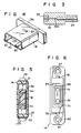
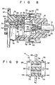
- FIG. 1 to 8 show an optical connector according to an embodiment of the present invention, in which
- an optical connector is provided with optical connector plug 12 attached to the end of optical fiber cable 10, and optical connector adaptor 14 to which the plug is to be connected.
- Plug 12 has plug body 16, in the form of thin box, fixed to cable 10, and floating holder 18 so arranged within the plug body to allow it to float.
- holder receiving space 20 which is open to the front end of the body and has a rectangular cross section
- fiber receiving space 22 which is open to the back end of the body and communicates with space 20.
- An inner surface of body 16 which defines space 20 is formed with regulating groove 21 which extendes throughout the entire periphery of the inner surface. Regulating groove 21, like space 20, has a rectangular cross section.
- regulating groove 21 On the rear end of plug body 16 is fixed optical fiber cable 10.
- Cable 10 includes tension wire 23 which is formed of ⁇ 1.2 mm steel wire, for instance, and embedded in polyethylene resin, two nylon jacketed fibers 24, and sheath 26 made of PVC (polyvinylchloride) covering wire 23 and fibers 24.
- An end portion of sheath 26 is fixed to plug body 16 by means of bush 28, and is located at the rear end of space 22.
- Wire 23 and optical fiber 24 extend frontward from the fixed end of sheath 26, and the wire is fixed to body 16 through wire holder 30 located within space 22.
- Each optical fiber 24 extends into holder receiving space 20, and ferrule 32 is fixed to the extended end of each fiber 24. As shown in Figs.
- ferrule 32 is formed of stainless steel, for instance, into a substantially cylindrical shape with a high dimensional accuracy.
- Fiber 24 is forcibly inserted into ferrule 32 and extends to the end of the ferrule.
- reference numeral 24a represents a bare fiber of fiber 24 formed of quartz and numeral 33 a ceramics tip with a capillary.
- Annular stopper 34 is provided on the outer periphery at the middle portion of each ferrule 32.
- floating holder 18 is formed into a rectangular cylindrical shape, and has a cross section which is similar to the cross section of holder receiving space 20 and smaller than that of space 20.
- holder 18 has rectangular flange 36 formed, as a regulating section, on the outer periphery at the rear end of holder 18.
- This flange 36 has a cross section which is similar in shape to that of regulating groove 21 of plug body 16 and smaller than that of the groove.
- flange 36 is thinner than the width of regulating groove 21.
- Projections 37 for engagement are formed on both the upper and lower surfaces of holder 18.
- Holder 18 is arranged in receiving space 20 of body 16 with flange 36 being located within regulating groove 21. Since holder 18 and flange 36 have cross sections smaller than those of space 20 and regulating groove 21, respectively, the holder is so arranged within space 20 as to allow its free movement in x, y and z directions.
- partition wall 38 which divides inside the holder into adaptor fitting recess 40 which is open to the front end of the holder, and retaining element fitting recess 42 which is open to the rear end of the holder, i.e., on the side of flange 36.
- a pair of through-holes 43 are formed in partition wall 38 and extend along the axis of holder 18. The distal end portions of ferrules 32 are inserted into through-holes 43 to be slidable along the respective axis, and project frontward from holder 18.
- Retaining element 46 formed with a pair of fiber insertion holes 44 is fitted into recess 42.
- each ferrule 32 is inserted into each insertion hole 44 Into each insertion hole 44 are loosely inserted the proximal end portion of corresponding ferrule 32 and optical fiber 24.
- Coil spring 48 is arranged around the proximal end portion of each ferrule 32, and one end of the spring is in contact with stopper 34 of the ferrule and the other end is in contact with retaining element 46.
- ferrule 32 is thus urged frontward of holder 18 with force of about 800 to 1200 g, and stopper 34 is held in contact with partition wall 38.
- each ferrule 32 is pressed by spring 48, and is allowed to move backward along the axis of ferrule 32 until spring 48 completely contracts.
- Each ferrule 32 is prevented from rotating by an anti-rotation pin which is not shown. While holder 18 is held within plug body 16, each fiber 24 is loose between ferrule 32 and the end of cable sheath 26.
- lock mechanism 50 for locking plug 12 and adaption 14 in a connected state when plug 12 is connected to adaptor 14.
- Lock mechanism 50 has a pair of lock levers 52 which are rotatably supported on both sides of body 16, respectively. More detailed, upper and lower support peices 54 extend from each said of body 16, and supporting shaft 56 is rotatably provided between the support pieces. Lock lever 52 is rotatably supported on shaft 56. Distal end portion 52a of each lock lever 52 projects frontward from plug body 16. End portion 52a is formed with square hole 58 as an engaging section.
- Torsion spring 60 is arranged around each shaft 56, and lock levers 52 are urged by springs 60 toward body 16, that is, urged in that direction in which end portions 52a of levers 52 come close to each other.
- adaptor 14 is provided with body 62 of a rectangular pillar shape.
- first connecting portion 63 to which plug 12 is to be connected.
- second connecting portion 65 to which another optical connector plug (not shown) is to be connected.
- First connecting portion 63 has rectangular fitting frame 64 projecting from the front of body 62.
- flange 66 On the end edge at the back side of body 62 is formed flange 66 in which are formed a pair of fixing holes 67.
- the inner surface of frame 64 defines holder fitting recess 68 into which floating holder 18 of plug 12 is fitted.
- Recess 68 has a cross section of the same shape as that of holder 18 and slightly larger than the latter.
- the inner surface of frame 64 serves as guide surface 69 for guiding insertion of holder 18 into fitting recess 68.
- Frame 64 has a profile which is similar to the cross section of holder receiving space 20 of plug body 16 to allow its insertion into space 20. In other words, frame 64 is so formed that plug body 16 can be fitted on frame 64, and the frame itself forms fitting section 70.
- the outer surface of frame 64 forms guide surface 71 for guiding the fitting of plug body 16 onto the frame.
- engaging holes 80 In the upper and lower walls of frame 64 are formed engaging holes 80 to which engaging projections 37 of floating holder 18 are fitted, respectively.
- projection 72 On the bottom of recess 68 is formed projection 72 which is to be fitted to recess 40 of floating holder 18.
- a pair of parallel ferrule insertion holes 74 are formed in body 62. Each insertion hole 74 has an end open to projection 72, i.e., the bottom of fitting recess 68, and the other end open to the back of body 62.
- a pair of annular threaded portions 76 constituting second connecting portion 65 are formed on the back of body 62. Each threaded portion 76 communicates with the other end of the corresponding insertion hole 74.
- a single core type optical connector plug (not shown) is to be connected to each threaded portion 76.
- projection 78 On each side of body 64 is formed projection 78 for engaging with square hole 58 of corresponding lock lever 52 when plug 12 is connected to adaptor 14.
- Each insertion hole 74 is machined with high accuracy in its inner diameter so that ferrule 32 inserted into it does not move inside it.
- connection of the optical connector having the above structure is performed in the following manner.
- first plug 12 is inserted to adaptor 14 while the end of floating holder 18 is fitted to holder fitting recess 68 of adaptor 14.
- the rear surface of flange 36 of holder 18 comes into contact with rear surface 21a of regulating groove 21 on plug body 16, and the holder is pushed by this rear surface 21a.
- frame 64 of adaptor 14 goes into holder receiving space 20 of plug body 16, and at the same time, projection 72 on adaptor 14 goes into fitting recess 40 formed on the end of holder 18.
- the distal end of each lock lever 52 on plug 12 comes into contact with corresponding projection 78 on adaptor 14, and the levers are rotated in the direction away from each other.
- FIG. 7B and 8 show the condition immediately after plug 12 is connected to adaptor 14.
- flange 36 of holder 18 comes into contact with the end of fitting frame 64, and projection 72 on adaptor 14 is fitted in recess 40 of the holder.
- ferrules 32 are inserted into ferrule insertion holes 74 of adaptor 14, respectively.
- engaging projections 37 on holder 18 engage with engaging holes 80 of engagement frame 64, respectively, thereby holding the holder within the frame.
- projections 78 on adaptor 14 are inserted into square holes 58 of lock levers 52, respectively, thereby locking plug body 16 to adaptor 14.
- gap a is formed between the edge of square hole 58 and projection 78
- gap b larger than gap a is formed between the front surface of flange 36 of holder 18 and the front surface of regulating groove 21 which faces the former.
- Fig. 7C shows the condition where an external force along direction z is applied on plug body 16 or optical fiber cable 10 to pull it backward.
- plug body 16 moves until the edge of square hole 58 of lock lever 52 comes into contact with projection 78 on adaptor 14, and its further movement is prevented by the lock levers.
- gap c with the same width as gap a is defined between the rear surface of flange 36 and rear surface 21a of regulating groove 21.
- gap d is left, which is as large as gap b minus moving distance of flange assembly 16.
- gap e is defined between the outer surface of flange 36 of holder 18 and the inner surface of regulating groove 21 of plug body 16. This gap e prevents the movement of plug body 16 in the directions of x and y from being transferred to holder 18.
- An impact test was conducted, applying an imapct of 100G for 5 ms on the optical connector in the x-direction, y-direction, and z-direction, while keeping plug 12 coupled to adaptor 14, and also maintaining single-fiber connector plugs (not shown) connected to threaded portions 76.
- the test showed that no interruption of transmission of optical signals, which amount to more than 0.03 dB and are longer than 60 msec., took place.
- holder 18 holding the ferrules, so to speak floats, not being fixed to plug body 16, and can freely move.
- holder 18 in the state that holder 18 is fitted to frame 64 and locked thereto by the half lock mechanism, even if an external force, such as an impact, is applied to plug body 16 or the optical fiber, it does not act on the ferrules. No interruptions of transmission of optical signals occur.
- the optical connector can, therefore, ensure a reliable optical signal transmission. It is not only easy to operate, but also mechanically strong against vibration, impact, etc., and can therefore provide a very reliable optical signal transmission.
- the invention can apply to connectors for connecting one optical fiber to another, or more than two optical fibers to the same number of optical fibers, instead of connecting only two optical fiber to other two as practiced in the embodiment.
- the holder can have holes (i.e., engaging section), and the adaptor can have projections (i.e., stopping section).
- the same advantages can be obtained as in the embodiment wherein the holder has projections and the adaptor has holes.
- the holder can be provided with magnets, and the adaptor can be provided with magnetic parts, or vice versa.
- the lock mechanism for locking the plug body to the adaptor can be comprised of projections provided on the plug body, and lock levers provided on the adaptor.
- the mechanism can be so constructed that it can be operated by a single touch.
- the adaptor has the first connecting section to which a two-fiber plug can be coupled, and the second connecting section to which a single-fiber plug can be coupled.
- the second connecting section can have the same structure as the first connecting section, so that a two-fiber plug can be connected to it.
- an alignment sleeve having a slit, into which a ferrule can be inserted, can be provided in the hole of the adaptor.
Landscapes
- Physics & Mathematics (AREA)
- General Physics & Mathematics (AREA)
- Optics & Photonics (AREA)
- Mechanical Coupling Of Light Guides (AREA)
Claims (13)
- Connecteur optique destiné à la connexion de fibres optiques à des éléments optiques, comprenant :
un adaptateur (14) destiné à loger les éléments optiques et comprenant un tronçon (63) de connexion de fiche,
une fiche (12) de connecteur destinée à être connectée au tronçon (63) de connexion de fiche de l'adaptateur (14),
un mécanisme (50) de blocage de la fiche (12) sur l'adaptateur (14) lorsque la fiche (12) est raccordée à l'adaptateur (14),
la fiche (12) comprenant un corps (16) de fiche destiné à être ajusté sur le tronçon (63) de connexion de fiche de l'adaptateur, le corps (16) de fiche étant bloqué sur le tronçon (63) de connexion de fiche par le mécanisme (50) de blocage lorsque le corps (16) de fiche est ajusté sur le tronçon (63) de connexion de fiche, et
une virole (32) fixée à une extrémité d'une fibre optique (24) et supportée par la fiche (12),
caractérisé en ce que :
l'adaptateur (14) comporte un dispositif de coopération (80),
le tronçon (63) de connexion de fiche comprend une partie (70) d'ajustement de corps de fiche et une partie (68) d'ajustement d'organe de support,
le corps (16) de fiche est destiné à être monté et à être bloqué sur la partie (70) d'ajustement de corps de fiche,
la fiche (12) comprend un organe flottant (18) de retenue destiné à être monté sur la partie (68) d'ajustement d'organe de retenue, l'organe flottant de retenue (18) étant placé dans le corps de fiche (16) afin qu'il soit mobile en direction quelconque par rapport au corps de fiche (16) et ayant aussi un dispositif coopérant (37) destiné à coopérer avec le dispositif de coopération (80) de l'adaptateur afin qu'il bloque l'organe flottant de retenue (18) sur la partie (68) d'ajustement d'organe de retenue lorsque l'organe flottant de retenue (18) est monté sur la partie (68) d'ajustement d'organe de retenue, et
la virole (32) est supportée par l'organe flottant de retenue (18). - Connecteur optique selon la revendication 1, caractérisé en ce que le corps de fiche (16) a un espace (20) de logement d'organe de retenue qui débouche à la surface externe du corps de fiche, l'organe flottant de retenue (18) est placé dans l'espace de logement d'organe de retenue avec un certain espacement, et la fiche (12) comprend un dispositif de régulation destiné à empêcher le glissement de l'organe de retenue en dehors de l'espace de logement de l'organe de retenue.
- Connecteur optique selon la revendication 2, caractérisé en ce que l'adaptateur (14) comporte un corps (62) et un élément d'ajustement (64) qui dépasse du corps, l'élément d'ajustement ayant une surface externe délimitant une partie (70) d'ajustement de corps de fiche et une surface interne délimitant une partie (68) d'ajustement d'organe de retenue, et l'élément d'ajustement est formé avec une configuration telle qu'il peut être introduit dans l'espace (20) de logement d'organe de retenue.
- Connecteur optique selon la revendication 3, caractérisé en ce que l'élément d'ajustement (64) est formé avec une configuration tubulaire, la surface externe de l'élément d'ajustement ayant un profil analogue à celui de la section de l'espace (20) de logement d'organe de retenue, et la surface interne de l'élément d'ajustement ayant un profil analogue à celui de la coupe de l'organe flottant de retenue (18).
- Connecteur optique selon la revendication 3, caractérisé en ce que les trous de coopération (80) sont formés à la surface interne sur l'élément d'ajustement, et le tronçon coopérant (37) est formé à la surface externe de l'organe flottant de retenue (18).
- Connecteur optique selon la revendication 2, caractérisé en ce que le dispositif de régulation comprend une cavité (21) de régulation formée dans le corps (16) de fiche et débouchant dans l'espace (20) de logement d'organe de retenue, et une partie de régulation (36) dépassant de l'organe flottant de retenue (18) et placée dans la cavité de régulation avec un espacement.
- Connecteur optique selon la revendication 6, caractérisé en ce que la virole (32) a un axe et une partie d'extrémité externe dépassant de l'organe flottant de retenue (18), et l'organe flottant de retenue et la partie de régulation (36) sont disposés dans l'espace (20) de logement d'organe de retenue et la cavité de régulation (21) respectivement afin qu'ils soient mobiles en direction perpendiculaire à l'axe de la virole et dans la direction axiale de la virole.
- Connecteur optique selon la revendication 7, caractérisé en ce que la virole (32) est disposée dans l'organe flottant de retenue (18) afin que celui-ci soit mobile suivant l'axe de la virole et possède un organe d'arrêt (34) destiné à empêcher le glissement de la virole en dehors de l'organe de retenue, et l'organe flottant de retenue comprend un élément (48) de rappel de la virole dans le sens dans lequel la virole dépasse de l'organe de retenue.
- Connecteur optique selon la revendication 7, caractérisé en ce que l'adaptateur (14) a un trou d'insertion (74) dans lequel est introduite la partie d'extrémité externe de la virole (32) lorsque la fiche (12) est connectée à l'adaptateur.
- Connecteur optique selon la revendication 1, caractérisé en ce que le mécanisme de blocage (50) comporte une saillie (78) formée sur l'adaptateur (14), et un levier de blocage (52) monté sur le corps de fiche (16) et ayant un trou (58) qui coopère avec la saillie lorsque la fiche (12) est connectée à l'adaptateur.
- Connecteur optique selon la revendication 1, caractérisé en ce que l'adaptateur comprend un second tronçon de raccordement auquel est destinée à être raccordée l'autre fiche d'un connecteur optique, le second tronçon de raccordement étant opposé au premier tronçon de raccordement.
- Connecteur optique selon la revendication 1, caractérisé en ce que :
un câble (10) à fibre optique comporte ladite fibre optique (24) et un revêtement (26) qui la recouvre, le revêtement ayant une extrémité externe et la fibre optique (24) ayant une partie prolongée dépassant de l'extrémité externe du revêtement,
la virole (32) est fixée à la partie prolongée de la fibre optique (24),
le câble (10) à fibre optique a un fil de tension (23) enrobé dans le revêtement (26) et ayant une partie prolongée dépassant de l'extrémité externe du revêtement (26), et
le revêtement (26) et la partie prolongée du fil de tension (23) sont fixés au corps de fiche (16). - Connecteur optique selon la revendication 12, caractérisé en ce que la partie prolongée de la fibre optique (24) a du jeu entre une extrémité du revêtement (26) du câble (10) à fibre optique et la virole (32).
Applications Claiming Priority (2)
| Application Number | Priority Date | Filing Date | Title |
|---|---|---|---|
| JP289151/85 | 1985-12-24 | ||
| JP60289151A JPH077139B2 (ja) | 1985-12-24 | 1985-12-24 | 浮動ホルダ型光コネクタ |
Publications (3)
| Publication Number | Publication Date |
|---|---|
| EP0228063A2 EP0228063A2 (fr) | 1987-07-08 |
| EP0228063A3 EP0228063A3 (en) | 1989-08-02 |
| EP0228063B1 true EP0228063B1 (fr) | 1993-09-29 |
Family
ID=17739420
Family Applications (1)
| Application Number | Title | Priority Date | Filing Date |
|---|---|---|---|
| EP86117858A Expired - Lifetime EP0228063B1 (fr) | 1985-12-24 | 1986-12-22 | Connecteur optique |
Country Status (5)
| Country | Link |
|---|---|
| US (1) | US4759599A (fr) |
| EP (1) | EP0228063B1 (fr) |
| JP (1) | JPH077139B2 (fr) |
| KR (1) | KR900005739B1 (fr) |
| DE (1) | DE3689113T2 (fr) |
Cited By (13)
| Publication number | Priority date | Publication date | Assignee | Title |
|---|---|---|---|---|
| EP0330231A3 (en) * | 1988-02-26 | 1990-08-22 | Nippon Telegraph And Telephone Corporation | Plug-in connector |
| EP0398613A3 (fr) * | 1989-05-17 | 1991-02-27 | Yamaichi Electric Mfg. Co. Ltd.. | Mécanisme de serrage pour un connecteur d'un câble à fibres optiques multifilaires |
| FR2665581A1 (fr) * | 1990-07-16 | 1992-02-07 | Puritan Bennett Corp | Connecteur hybride electrique-optique. |
| EP0430107A3 (en) * | 1989-11-24 | 1992-09-23 | Nippon Telegraph And Telephone Corporation | Optical connector |
| US5242315A (en) * | 1992-05-21 | 1993-09-07 | Puritan-Bennett Corporation | Electrical-optical hybrid connector plug |
| US5436993A (en) * | 1993-01-21 | 1995-07-25 | Sirti S.P.A. | Multiple connector for multi-fibre optic ribbons |
| US5528711A (en) * | 1989-11-24 | 1996-06-18 | Nippon Telegraph And Telephone Corp. | Optical connector for connecting a plurality of optical plugs to a connector housing |
| US5537501A (en) * | 1989-11-24 | 1996-07-16 | Nippon Telegraph And Telephone Corporation | Optical connector |
| US5647043A (en) * | 1995-10-12 | 1997-07-08 | Lucent Technologies, Inc. | Unipartite jack receptacle |
| US5673346A (en) * | 1989-11-24 | 1997-09-30 | Nippon Telegraph And Telephone Corporation | Optical jack for plug-jack optical connector |
| WO2003071205A1 (fr) | 2002-02-25 | 2003-08-28 | BSH Bosch und Siemens Hausgeräte GmbH | Piece interieure pour appareil de refrigeration |
| WO2004015337A1 (fr) | 2002-08-05 | 2004-02-19 | BSH Bosch und Siemens Hausgeräte GmbH | Appareil frigorifique comprenant des pieces encastrees conductrices d'eau |
| DE202004021743U1 (de) | 2003-08-11 | 2010-08-19 | BSH Bosch und Siemens Hausgeräte GmbH | Kältegerät mit wasserführenden Einbauten |
Families Citing this family (36)
| Publication number | Priority date | Publication date | Assignee | Title |
|---|---|---|---|---|
| US5166995A (en) * | 1984-06-08 | 1992-11-24 | Amp Incorporated | Polarized connector |
| JPH0522887Y2 (fr) * | 1987-08-31 | 1993-06-11 | ||
| US4826277A (en) * | 1987-10-30 | 1989-05-02 | Amp Incorporated | Transition of a multiple fiber cable to single fiber cable |
| US5011246A (en) * | 1989-05-19 | 1991-04-30 | E. I. Du Pont De Nemours And Company | Housing for an opto-electronic device |
| US4978194A (en) * | 1989-08-28 | 1990-12-18 | Raynet Corporation | Stepped cable block |
| US5117479A (en) * | 1990-11-02 | 1992-05-26 | Amp Incorporated | Clamp for split cable of multiple optical fibers |
| SE500190C2 (sv) * | 1991-01-30 | 1994-05-02 | Bernd Stanitz | Flerkanals förbindelseanordning |
| US5109453A (en) * | 1991-02-25 | 1992-04-28 | Amp Incorporated | Optical fiber connector with latching beam mechanism |
| US5140663A (en) * | 1991-04-17 | 1992-08-18 | Amp Incorporated | Latching beam mechanism having plug stops for optical connector |
| US5133032A (en) * | 1991-04-17 | 1992-07-21 | Salter James R | Optical fiber connector |
| US5159654A (en) * | 1991-10-25 | 1992-10-27 | Optex Biomedical, Inc. | Multi-channel optical fiber connector |
| US5315679A (en) * | 1992-04-27 | 1994-05-24 | International Business Machines Corporation | Optical fibers duplex connector assembly |
| JP2780640B2 (ja) * | 1994-05-25 | 1998-07-30 | 住友電装株式会社 | 光ファイバーケーブルの接続コネクタ |
| US5553180A (en) * | 1995-01-17 | 1996-09-03 | Molex Incorporated | Adapter assembly for fiber optic connectors |
| US5608828A (en) * | 1995-09-12 | 1997-03-04 | Itt Corporation | Fiber optic connector apparatus |
| AU716587B2 (en) * | 1995-10-31 | 2000-03-02 | Indigo Medical, Incorporated | Fiber optic radiation transmission system, connector system for an optical fiber, and methods of using same |
| NL1002955C2 (nl) * | 1996-04-26 | 1997-10-28 | Framatome Connectors Belgium | Multifiber connectorplug. |
| JP3335277B2 (ja) * | 1996-05-07 | 2002-10-15 | 株式会社エンプラス | 線材保持具及び光ファイバ用コネクタ |
| US6007256A (en) * | 1996-09-24 | 1999-12-28 | Sumitomo Wiring Systems, Ltd. | Optical connector that reduces the number of components used, that facilitates assembly, and that prevents spontaneous disassembly, and structure for attaching a boot to an optical connector |
| US5926596A (en) * | 1998-01-28 | 1999-07-20 | The Whitaker Corporation | Overmolded alignment ferrule |
| US6224268B1 (en) | 1998-04-23 | 2001-05-01 | The Whitaker Corporation | Plug housing with attached cantilevered latch for a fiber optic connector |
| US6454464B1 (en) | 1998-12-28 | 2002-09-24 | Computer Crafts, Inc. | Fiber optic connectors and transceiver test devices |
| US6464408B1 (en) | 1998-12-28 | 2002-10-15 | Computer Crafts, Inc. | Fiber optic connectors |
| EP1072918B1 (fr) * | 1999-07-26 | 2005-03-30 | Diamond SA | Elément de connecteur pour connexion optique |
| DE50009898D1 (de) * | 1999-07-26 | 2005-05-04 | Diamond Sa | Steckerteil für eine optische Steckverbindung |
| EP1072920A1 (fr) * | 1999-07-26 | 2001-01-31 | Diamond SA | Elément de connecteur pour connexion optique |
| US6511230B1 (en) | 2000-02-04 | 2003-01-28 | Panduit Corp. | Fiber optic connection system |
| WO2002042818A1 (fr) * | 2000-11-21 | 2002-05-30 | Euromicron Werkzeuge Gmbh | Connecteur pour guides d'ondes optiques comprenant un boitier de connecteur |
| US6485189B1 (en) | 2001-05-09 | 2002-11-26 | Stratos Lightwave, Inc. | High density multiple fiber optic connector |
| JP2002341182A (ja) * | 2001-05-14 | 2002-11-27 | Auto Network Gijutsu Kenkyusho:Kk | 光コネクタ |
| US6734435B2 (en) * | 2001-05-29 | 2004-05-11 | Rae Systems, Inc. | Photo-ionization detector and method for continuous operation and real-time self-cleaning |
| JP5277962B2 (ja) * | 2006-11-13 | 2013-08-28 | 住友電気工業株式会社 | ホルダ及び融着接続機及び光コネクタの組立方法 |
| US20110158588A1 (en) * | 2009-12-25 | 2011-06-30 | Hon Hai Precision Industry Co., Ltd. | Cable assembly having floatable optical module |
| JP2012220731A (ja) * | 2011-04-08 | 2012-11-12 | Yazaki Corp | 光コネクタ |
| EP2987013B1 (fr) | 2013-04-15 | 2020-04-08 | Huber+Suhner Ag | Ensemble connecteur optique |
| CN116601834A (zh) * | 2020-10-30 | 2023-08-15 | 康宁研究与开发公司 | 具有防风雨套环的光纤连接器 |
Family Cites Families (12)
| Publication number | Priority date | Publication date | Assignee | Title |
|---|---|---|---|---|
| US3596018A (en) * | 1969-06-25 | 1971-07-27 | Howard Gross | Electrical connection device for vehicles |
| US3840839A (en) * | 1973-02-01 | 1974-10-08 | Akzona Inc | Asymmetrical electrical connector with aligning means |
| DE2933790C2 (de) * | 1979-08-21 | 1982-05-27 | Standard Elektrik Lorenz Ag, 7000 Stuttgart | Lösbare Verbindungsvorrichtung für Lichtleiter |
| FR2479484A1 (fr) * | 1980-03-26 | 1981-10-02 | Perena | Connecteur de fibres optiques |
| JPS5878111A (ja) * | 1981-11-04 | 1983-05-11 | Sumitomo Electric Ind Ltd | 複芯コネクタ |
| JPS6037529Y2 (ja) * | 1981-12-28 | 1985-11-08 | 日本電信電話株式会社 | プラグイン形光コネクタ |
| US4681398A (en) * | 1983-01-03 | 1987-07-21 | Switchcraft, Inc. | Fiber optic connector and method of assembly |
| JPS59140410A (ja) * | 1983-01-31 | 1984-08-11 | Fujitsu Ltd | 光コネクタ結合構造 |
| GB2149589B (en) * | 1983-11-08 | 1988-06-02 | Davis & Son John | A connector for releasable connection of a first to a second apparatus |
| JPS60152109U (ja) * | 1984-03-19 | 1985-10-09 | デユポン ジヤパン リミテツド | 光デ−タリンク |
| AU577099B2 (en) * | 1984-03-19 | 1988-09-15 | E.I. Du Pont De Nemours And Company | Receptacle, plug and optical connector |
| US4682848A (en) * | 1984-10-03 | 1987-07-28 | Lockheed Corporation | Underwater-mateable optical fiber connector |
-
1985
- 1985-12-24 JP JP60289151A patent/JPH077139B2/ja not_active Expired - Fee Related
-
1986
- 1986-12-15 KR KR1019860010728A patent/KR900005739B1/ko not_active Expired
- 1986-12-19 US US06/943,769 patent/US4759599A/en not_active Expired - Lifetime
- 1986-12-22 DE DE86117858T patent/DE3689113T2/de not_active Expired - Lifetime
- 1986-12-22 EP EP86117858A patent/EP0228063B1/fr not_active Expired - Lifetime
Cited By (16)
| Publication number | Priority date | Publication date | Assignee | Title |
|---|---|---|---|---|
| EP0330231A3 (en) * | 1988-02-26 | 1990-08-22 | Nippon Telegraph And Telephone Corporation | Plug-in connector |
| EP0398613A3 (fr) * | 1989-05-17 | 1991-02-27 | Yamaichi Electric Mfg. Co. Ltd.. | Mécanisme de serrage pour un connecteur d'un câble à fibres optiques multifilaires |
| US5528711A (en) * | 1989-11-24 | 1996-06-18 | Nippon Telegraph And Telephone Corp. | Optical connector for connecting a plurality of optical plugs to a connector housing |
| US5537501A (en) * | 1989-11-24 | 1996-07-16 | Nippon Telegraph And Telephone Corporation | Optical connector |
| EP0430107A3 (en) * | 1989-11-24 | 1992-09-23 | Nippon Telegraph And Telephone Corporation | Optical connector |
| US5673346A (en) * | 1989-11-24 | 1997-09-30 | Nippon Telegraph And Telephone Corporation | Optical jack for plug-jack optical connector |
| US5404416A (en) * | 1989-11-24 | 1995-04-04 | Nippon Telegraph & Telephone Corporation | Optical connector plug |
| FR2665581A1 (fr) * | 1990-07-16 | 1992-02-07 | Puritan Bennett Corp | Connecteur hybride electrique-optique. |
| EP0467631A3 (en) * | 1990-07-16 | 1992-04-01 | Puritan-Bennett Corporation | Electrical-optical hybrid connector |
| US5242315A (en) * | 1992-05-21 | 1993-09-07 | Puritan-Bennett Corporation | Electrical-optical hybrid connector plug |
| US5436993A (en) * | 1993-01-21 | 1995-07-25 | Sirti S.P.A. | Multiple connector for multi-fibre optic ribbons |
| US5647043A (en) * | 1995-10-12 | 1997-07-08 | Lucent Technologies, Inc. | Unipartite jack receptacle |
| WO2003071205A1 (fr) | 2002-02-25 | 2003-08-28 | BSH Bosch und Siemens Hausgeräte GmbH | Piece interieure pour appareil de refrigeration |
| US10465973B2 (en) | 2002-02-25 | 2019-11-05 | BSH Hausgeräte GmbH | Inner part for a refrigerating device |
| WO2004015337A1 (fr) | 2002-08-05 | 2004-02-19 | BSH Bosch und Siemens Hausgeräte GmbH | Appareil frigorifique comprenant des pieces encastrees conductrices d'eau |
| DE202004021743U1 (de) | 2003-08-11 | 2010-08-19 | BSH Bosch und Siemens Hausgeräte GmbH | Kältegerät mit wasserführenden Einbauten |
Also Published As
| Publication number | Publication date |
|---|---|
| KR900005739B1 (ko) | 1990-08-09 |
| KR870006421A (ko) | 1987-07-11 |
| US4759599A (en) | 1988-07-26 |
| EP0228063A3 (en) | 1989-08-02 |
| DE3689113T2 (de) | 1994-03-31 |
| JPS62148907A (ja) | 1987-07-02 |
| JPH077139B2 (ja) | 1995-01-30 |
| DE3689113D1 (de) | 1993-11-04 |
| EP0228063A2 (fr) | 1987-07-08 |
Similar Documents
| Publication | Publication Date | Title |
|---|---|---|
| EP0228063B1 (fr) | Connecteur optique | |
| US6179482B1 (en) | Optical connector and housing for optical connector | |
| AU685710B2 (en) | Optical fiber connector plug and optical fiber connector | |
| US11054586B2 (en) | Optical connector and optical connection structure | |
| US11940655B2 (en) | Optical connector and optical connection structure | |
| EP3474052B1 (fr) | Connecteur optique et structure de connexion optique | |
| KR920010946B1 (ko) | 과학 섬유용 분리형 접속기 | |
| KR100283420B1 (ko) | 광커넥터 | |
| GB2045454A (en) | Connecting optic fibres | |
| JP2024075729A5 (fr) | ||
| US6394662B1 (en) | Optical fibre connector | |
| US4818061A (en) | Ferrule for connecting optical fibers and optical connector using it | |
| US20160320566A1 (en) | Connector for collimated optical fiber | |
| JP7786395B2 (ja) | 光コネクタ及び光接続構造 | |
| JP4255803B2 (ja) | 光コネクタ | |
| JPS6261923B2 (fr) | ||
| JPH04235508A (ja) | 光コネクタ | |
| JPS6128909A (ja) | 光コネクタ | |
| JPH04174407A (ja) | 光コネクタ | |
| EP0574462B1 (fr) | Raccord pour fibre optique et son procede de production | |
| JP2519233B2 (ja) | 光フアイバ用多心一括切替スイツチ | |
| JPH06265757A (ja) | コネクタ | |
| JP2501499Y2 (ja) | 光ファイバ用簡易コネクタ | |
| JPS60213914A (ja) | 光フアイバ接続用コネクタ | |
| JPH11326702A (ja) | 光コネクタ |
Legal Events
| Date | Code | Title | Description |
|---|---|---|---|
| PUAI | Public reference made under article 153(3) epc to a published international application that has entered the european phase |
Free format text: ORIGINAL CODE: 0009012 |
|
| 17P | Request for examination filed |
Effective date: 19870119 |
|
| AK | Designated contracting states |
Kind code of ref document: A2 Designated state(s): DE FR GB |
|
| PUAL | Search report despatched |
Free format text: ORIGINAL CODE: 0009013 |
|
| AK | Designated contracting states |
Kind code of ref document: A3 Designated state(s): DE FR GB |
|
| 17Q | First examination report despatched |
Effective date: 19920309 |
|
| GRAA | (expected) grant |
Free format text: ORIGINAL CODE: 0009210 |
|
| AK | Designated contracting states |
Kind code of ref document: B1 Designated state(s): DE FR GB |
|
| REF | Corresponds to: |
Ref document number: 3689113 Country of ref document: DE Date of ref document: 19931104 |
|
| ET | Fr: translation filed | ||
| PLBE | No opposition filed within time limit |
Free format text: ORIGINAL CODE: 0009261 |
|
| STAA | Information on the status of an ep patent application or granted ep patent |
Free format text: STATUS: NO OPPOSITION FILED WITHIN TIME LIMIT |
|
| 26N | No opposition filed | ||
| REG | Reference to a national code |
Ref country code: GB Ref legal event code: IF02 |
|
| PGFP | Annual fee paid to national office [announced via postgrant information from national office to epo] |
Ref country code: FR Payment date: 20051208 Year of fee payment: 20 |
|
| PGFP | Annual fee paid to national office [announced via postgrant information from national office to epo] |
Ref country code: DE Payment date: 20051215 Year of fee payment: 20 |
|
| PGFP | Annual fee paid to national office [announced via postgrant information from national office to epo] |
Ref country code: GB Payment date: 20051221 Year of fee payment: 20 |
|
| PG25 | Lapsed in a contracting state [announced via postgrant information from national office to epo] |
Ref country code: GB Free format text: LAPSE BECAUSE OF EXPIRATION OF PROTECTION Effective date: 20061221 |
|
| REG | Reference to a national code |
Ref country code: GB Ref legal event code: PE20 |