EP0228101A2 - Procédé de surveillance de plusieurs lignes de transmission numérique et dispositif pour la réalisation du procédé - Google Patents
Procédé de surveillance de plusieurs lignes de transmission numérique et dispositif pour la réalisation du procédé Download PDFInfo
- Publication number
- EP0228101A2 EP0228101A2 EP86201888A EP86201888A EP0228101A2 EP 0228101 A2 EP0228101 A2 EP 0228101A2 EP 86201888 A EP86201888 A EP 86201888A EP 86201888 A EP86201888 A EP 86201888A EP 0228101 A2 EP0228101 A2 EP 0228101A2
- Authority
- EP
- European Patent Office
- Prior art keywords
- frame
- word
- data
- line
- address
- Prior art date
- Legal status (The legal status is an assumption and is not a legal conclusion. Google has not performed a legal analysis and makes no representation as to the accuracy of the status listed.)
- Withdrawn
Links
- 230000005540 biological transmission Effects 0.000 title claims abstract description 46
- 238000012544 monitoring process Methods 0.000 title claims abstract description 23
- 238000000034 method Methods 0.000 title claims description 24
- 230000015654 memory Effects 0.000 claims description 25
- 230000009977 dual effect Effects 0.000 claims description 12
- 238000001514 detection method Methods 0.000 claims description 6
- 238000004804 winding Methods 0.000 claims description 5
- 238000003780 insertion Methods 0.000 claims description 4
- 230000037431 insertion Effects 0.000 claims description 4
- 230000001172 regenerating effect Effects 0.000 claims 1
- 125000004122 cyclic group Chemical group 0.000 abstract 1
- 238000005259 measurement Methods 0.000 abstract 1
- 238000010586 diagram Methods 0.000 description 7
- 238000012806 monitoring device Methods 0.000 description 6
- 230000003111 delayed effect Effects 0.000 description 5
- 230000004044 response Effects 0.000 description 4
- 230000008929 regeneration Effects 0.000 description 3
- 238000011069 regeneration method Methods 0.000 description 3
- 238000012546 transfer Methods 0.000 description 3
- 230000000694 effects Effects 0.000 description 2
- 238000002955 isolation Methods 0.000 description 2
- 230000002123 temporal effect Effects 0.000 description 2
- 230000004913 activation Effects 0.000 description 1
- 230000006399 behavior Effects 0.000 description 1
- 238000010276 construction Methods 0.000 description 1
- 230000006378 damage Effects 0.000 description 1
- 230000006866 deterioration Effects 0.000 description 1
- 230000007774 longterm Effects 0.000 description 1
- 238000012423 maintenance Methods 0.000 description 1
- 238000012986 modification Methods 0.000 description 1
- 230000004048 modification Effects 0.000 description 1
- 230000003449 preventive effect Effects 0.000 description 1
- 230000008569 process Effects 0.000 description 1
- 230000009467 reduction Effects 0.000 description 1
- 230000008439 repair process Effects 0.000 description 1
- 238000000926 separation method Methods 0.000 description 1
- 238000012360 testing method Methods 0.000 description 1
- 230000001960 triggered effect Effects 0.000 description 1
Images


Classifications
-
- H—ELECTRICITY
- H04—ELECTRIC COMMUNICATION TECHNIQUE
- H04B—TRANSMISSION
- H04B17/00—Monitoring; Testing
- H04B17/40—Monitoring; Testing of relay systems
Definitions
- the invention relates to a method for monitoring a plurality of digital transmission lines according to the preamble of claim 1.
- Digital transmission lines are to be understood in particular as all types of PCM and data lines.
- the invention further relates to an arrangement for carrying out the method mentioned.
- the method works with deliberately used violations of the transmission code, which are recognized by each intermediate point and cause the return channel to loop in each desired intermediate point. Due to the loop, it is not possible to carry out the procedure during normal operation. Rather, it is necessary to remove the transmission lines to be tested from the normal To take operation. This makes monitoring tedious when numerous transmission lines have to be monitored and / or makes ongoing, automatic monitoring difficult.
- Monitoring systems are also known, e.g. from document EP-B-0 044 556, in which each regenerator detects the number of code violations that pass through it and records them. The information about transmission errors obtained in this way can be queried, evaluated centrally and used for fault location by a central monitoring point. These monitoring systems are relatively complex and yet only give a limited overview of the functionality of the transmission lines to be monitored, in terms of time and space.
- the object of the invention is therefore to provide a relatively simple device for monitoring digital transmission lines, which constantly provides a complete overview of the temporal and spatial interference behavior. This should make it possible, in the short term, not only to identify and locate long-term errors, but also sporadically occurring errors.
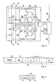
- Fig. 1 shows a transmission device with a plurality of parallel digital transmission lines L, L ', e.g. PCM or data lines.
- Each of these lines L, L ' consists of several line sections 14 and 14', which are delimited on both sides by a regenerator unit 12 and 12 ', respectively.
- the transmission lines are, for example, 2 Mbit / s data lines
- symmetrical wire pairs are used for the sections 14, 14 ', which are combined to form a single cable.
- a typical length of the sections 14, 14 ' is then 1.8 km.
- two transmission lines L and L ' are in pairs summarized to duplex connections, which for practical reasons leads to the paired combination of the associated regenerator units 12 and 12 'to an intermediate amplifier 13.
- a typical number for the number of 2 Mbit / s data lines on a cable is sixty-four.
- the line sections 14 of these data lines each require sixty-four regenerator units 12 and 12 ', which are combined into thirty-two repeaters 13 and spatially combined form the essential part of an intermediate point 15.
- the number of repeaters 13 required in a line L, L ' depends on the length of the line, with another typical number twenty-four generally not being exceeded.
- regenerator units 12 and 12' are connected to electronic devices 16, the construction of which is not of interest here. These electronic devices 16 are in turn connected to further devices, not shown, by precisely defined interfaces, which are generally internationally standardized and represented by circles in FIG. 1.
- a monitoring device which is also necessarily spatially extended and will be described below, is used.
- Each regenerator unit 12 or 12 ' has in addition to a regenerator 20 or 20' for the equalization and regeneration of the continuously incoming and outgoing bits of the transmission line sections 14, 14 'an error monitor 29 or 29'. This is connected to the regenerator 20, 20 'and responds to any code violation of the transmission code used, e.g. HDB3, and saves it as information. Each code violation thus forms an error event.
- Each error monitor 29, 29 ' is connected in its intermediate point 15 via a connection 43 to a collector 42.
- These collectors 42 are connected via a directed line 38, e.g. a data line which is slow in comparison to the digital transmission lines 14, connected in series.
- an evaluator 48 is also connected as a final unit to the end of this line 38.
- the monitoring device comprises the entirety of all error monitors 29, 29 'and collectors 42, the connections 43 between them, the directed line 38 and the evaluator 48.
- Fig. 2 shows a block diagram of an intermediate amplifier 13.
- This comprises as described two regenerators 20, 20 ', which are connected on both sides with transmission line sections 14 and 14'.
- everybody Regenerator 20, 20 ' is further connected to the associated error monitor 29, 29'.
- error detectors 30, 30 ' which respond to the respective code errors mentioned and are known, for example, from said document CH 541 910.
- Both error detectors 30, 30 ' are connected downstream memories 33, 33', which register the errors found. In the simplest case, these are dual counters for adding up the number of errors.
- the error monitors 29, 29 ' also include readout circuits 34 and 34', with the aid of which the memories 33, 33 'can be read out and reset.
- the error monitors 29, 29 ' are connected via a separator 35 to the collector 42 of the respective intermediate point.
- This isolator 35 is used for potential isolation between the collector 42 and the regenerator units 12, 12 'and is for example designed as an optocoupler or preferably as a pulse transformer.
- the potential separation is necessary, in particular when the intermediate amplifiers 13 are supplied remotely, in order to eliminate the influence of the non-uniform potentials.
- the collector 42 is connected to an incoming and an outgoing line section 38 and to all intermediate amplifiers 13 of the respective intermediate point 15, which is indicated in FIG. 2 by the open connections 43.
- FIG. 3 shows the block diagram of a collector 42. This includes a detection circuit 60 for detecting the line 38 that is directed incoming signals or the frames 49 still to be discussed, a delay unit 68 for delaying the incoming signals, a switching logic 66 controlled by a switching controller 65, a selection controller 61 and an interrogation unit 64.
- the collector 42 operates in time with the directed line 38, which is symbolized by the arrow "clock”.
- the switching logic 66 corresponds to a three-pole changeover switch and is shown accordingly.
- the interrogation unit 64 is connected via the various connections 43 to the intermediate amplifiers 13, not shown in FIG. 3.
- the monitoring device described so far works as follows:
- the error detectors 30, 30 ' continuously monitor the bit stream on the line sections 14 and 14' in each repeater 13. With each code violation they respond and write an error message in the assigned memory 33 or 33 '. In the case of a dual counter, this means incrementing the respective counter by 1.
- the collector 42 which is furthest away from the evaluator 48, also sends a continuous bit stream with a word and frame structure, also continuously.
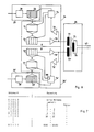
- the frame 49 shown in Fig. 4 begin with a synchronization word 50, followed by an address word 51 for identifying a pair of transmission lines 14, 14 '. These two words 50, 51 are followed by a number of identical data words 52, the number being greater or equal to the maximum number of regenerator units 12 of a transmission line L, L ', that is, according to the typical number mentioned above, for example twenty-four.
- the next frame 49 immediately follows the last data word 52.
- the content of the data words 52 initially characterizes them as empty, ie as an empty word.
- the frames 49 successively pass through all the collectors 42 and the sections of the directed lines 38 lying between them and finally reach the evaluator 48.
- the response circuit 60 recognizes the synchronization 50 and the address word 51 for each incoming frame 49.
- the selection controller 61 selects the intermediate amplifier 13 of the respective intermediate point 15 corresponding to the respective address, specifically via the interrogation unit 64, which in each case assigned of the connections 43 switches actively. Via this connection, 38 polling pulses are then sent to the selected repeater 13 in time with the line. These pulses reach the readers 34 and 34 'via the isolator 35, which then read out the memories 33 and 33' bit by bit.
- the read bits reach, in the opposite direction via the isolator 35 and the respective connection 43 mentioned, the interrogation unit 64, which it sends out via the switching logic 66 to the outgoing line 38.
- the incoming frames 49 run in each collector 42 after passing through the detection circuit 60 via the delay unit 68 and in parallel therewith via a direct connection to the switching logic 66.
- the switching logic 66 By suitable switching of the switching logic 66 with the aid of the switching control 65, the synchronization word 50 and the address word 51 reach each frame 49 the outgoing line 38 without delay, but the data words 52 delayed, namely by the length of a data word. This creates a gap in the bit stream into which the bits read out by the respectively selected intermediate amplifier 13 enter as a newly formed data word.
- word insertion buffer insertion
- the switching logic 66 is reset to its original switching position, which means the destruction of the last, now redundant, empty data word 52 of the previous frame 49.
- the length of the frames 49 or the number of data words 52 remains constant in this way.
- the frames 49 fill in the manner described with successive passage through all collectors 42 word for word from front to back with query information. If the transmission line L, L 'has fewer repeaters 13 than the frame 49 data words 52, then the last data words 52 remain unchanged and thus recognizable as empty words.
- Each frame 49 contains the query information of all repeaters 13 with the same address, i.e. two paired transmission lines L, L 'or a duplex line. If the addresses of the successive frames 49 are changed cyclically, all transmission lines L, L 'are queried in succession.
- An inexpensive 1 second is selected as the query clock, since the second, as the smallest unit of time, is of particular importance for monitoring purposes.
- the query information arriving in the evaluator 48 is continuously analyzed and suitably evaluated, stored and / or displayed.
- the strategies for this are not the subject of the invention.
- collector 42 furthest away from the evaluator 48 or another collector 42 fails, e.g. due to the failure of an electrical component, this may result in the entire monitoring device described so far from what is intolerable. 5, another collector 42a is therefore described which overcomes this problem.
- This further collector 42a has, like the collector 42 according to FIG. 3, a detection circuit 60, a selection control 61, an interrogation unit 64, a switching control 65, a switching logic 66 and a delay unit 68. Furthermore, it has a frame and Address generator 62 and a comparator 63.
- the collector 42a continuously generates a bit and frame clock in accordance with FIG. 4 in time with the directional line 38 with the aid of the frame and address generator 62. It continues to transmit in the middle switching position brought about by the switching controller 65 Switching logic 66 for each frame 49 the synchronization 50 and the address word 51 on the outgoing line 38. Then he causes the selection control 61 and the switching control 65 to select the connection 43 designated in the transmitted address, to query the memories 33, 33 'of the selected repeater 13 and to read out the data word 52 thus formed on the outgoing line 38.
- an incoming second frame 49 runs from the incoming line 38 into the collector 42 '.
- This second frame 49 is analyzed in the detection circuit 60 and delayed in parallel in the delay unit 68. If the comparator 63 determines that the synchronization 50 and address word 51 of the first frame generated by the frame and address generator 62 match the analyzed synchronization and address word of the second frame 49, the switching controller 65 uses the delay unit 68 to Delayed data words 52 of the second frame 49 are then transmitted to the outgoing line 38 directly after the words 50 and 51 of the first frame 49 which have already been sent out.
- each collector 42a forms a frame regenerator, which automatically becomes a frame generator if the incoming frames fail.
- the monitoring point 48 receives information about where the location is with a missing frame match. This means that a monitoring device equipped with collectors 42a is self-monitoring in contrast to one with collectors 42.
- the synchronism between the generation of the first frames by the frame and address generator 62 and the second frame arriving via the line 38 is carried out via a synchronization device (not shown) which is known per se and which also generates the clock if the clock fails on the incoming line .
- the insertion of the bits read out from the memories 33, 33 'of the respectively selected intermediate amplifier 13 as a data word into the respective frame 49 can be done in a variation to what has been described in that the bits either correspond to a rigid definition in a respectively predetermined data word 52 of the respective frame 49 can be read in or attached to the end of the respective frame 49.
- the synchronization word 50, the address word 51 and the first incoming data word 52 is delayed by the length of a data word 52, this delayed data word 52 is destroyed and the subsequent data words 52 are appended to words 50 and 51 without delay.
- Fig. 6 shows the structure of a data word 52. Then each data word is divided into three areas into two areas A and B for the bits or for the information from the respectively assigned memories 33 and 33 'of a repeater 13 and a parity bit P.
- the areas A and B each comprise five bits, for example, so that a data word 52 then comprises a total of eleven bits.
- FIG. 7 shows a table for the meaning of the five bits of the areas A or B in each case. Five zeros corresponding to the top line of the table mean that no feedback has been given by the selected intermediate amplifier 13. This leaves e.g. infer the failure of the assigned supply.
- the combination 10000 means empty word and is written into all data words 52 when frame 49 is generated.
- the four preceding bits mean the decimal exponent of the most significant bit of the dual count value in one as a dual counter trained memory 33, 33 '. If this dual counter has 15 digits, then the four bits can be used to transfer the decimal count values specified in the table in the right column. It is clear that due to the data reduction to the most significant bit of the respective count value, the correct value and otherwise a numerical range variable by a factor of 2 can only be transmitted and displayed in the case of count value 0 or 1. However, this is sufficient, since it is not the absolute, but only the correct number of errors that is important for assessing a fault situation.
- Fig. 8 shows a more detailed embodiment for the error monitors 29, 29 ', the associated readout circuits 34 and 34' and the isolator 35.
- the error monitors 29, 29 ' include the error detectors 30 and 30', which are already in connection with Fig. 2nd have been discussed, and this downstream dual counter as memory 33 and 33 '.
- the dual counters are e.g. 15 digits, corresponding to the description of FIG. 7.
- the readout circuits 34 and 34 ' comprise for each memory 33 and 33' a significance encoder 71, 71 ', which takes over the respective count value in parallel from the assigned memory 33, 33' and then outputs a 5-bit word A or B respectively , which indicates the counter level of the dual counter in which the most significant bit of the respective counter value was.
- These 5-bit words A and B are taken over by 5-bit shift registers 72, 72 'in parallel.
- the isolator 35 is in the example shown a pulse transformer 75 with a primary winding 76 and two secondary windings 77, 77 '.
- the primary winding 76 is connected to the associated collector 42, not shown, via the connection 43, which is designed as a two-wire line.
- the secondary windings 77, 77 ' effect the galvanic isolation of the associated circuits from one another and from the connection 43, voltage strengths of over 1000 V being necessary.
- the device according to FIG. 8 operates as follows:
- the collector 42 not shown, sends short query pulses to the connection 43 in synchronism with the respective frame 49 and in the bit clock of the frame. These query pulses pass through the transformer 75 and reach the read controllers 74, 74 'via the amplifiers 78, 78'.
- the first pulse of a pulse series triggers signals which stop the counters 33, 33 'and cause the transfer of the collected information into the shift registers 72 and 72', respectively.
- the second to sixth pulses in each case cause the shift register 72 to be read out step-by-step, in that a pulse is sent to the connection 43 via the amplifier 79 at logic 1, so to speak as a response to the respective query pulse, and no pulse at logic 0.
- these response pulses are registered as area A of a data word 52 and inserted into the frame 49.
- the respective seventh to eleventh interrogation pulses accordingly effect the step-by-step reading of the shift register 72 ', ie the area B of the data word 52 mentioned.
- the associated parity bit P is subsequently added to the reading out of the areas A and B.
- the query pulses arriving via connection 43 each reach both read controllers 74 and 74 '.
- the latter (74 ') has a delay 80, which prevents the second to sixth pulses from reading the shift register 72'.
- a corresponding device is not required in the read controller 74, since the seventh to eleventh pulses each act on the shift register 72 which has already been read out and thus is empty, no pulses being emitted via the amplifier 79.
- connection of the collectors 42 to the intermediate amplifiers 13 of the respective intermediate point takes place 15 through one connection 43 each.
- the interrogation unit 64 of each collector 42 selects the respective connection 43 in accordance with the respectively read address and sends out the respective request pulses to it and receives the response via it.
- a variant of this is a bus line which connects all the repeaters 13 together and via which all the repeaters are polled with the aid of addressed polling pulses.
- the units of the collector 42 or 42 ' in particular the selection control 61 and the interrogation unit 64, can be constructed either as hard-wired logic or as a program-controlled microprocessor.
- the logic units of the repeaters 13, 13 ' in particular the memories 33, 33' and the readout circuits 34, 34 ', can be constructed using microprocessors.
- a self-clocking code for example the Manchester code or the CMI code (coded mark inversion), is recommended as the transmission code on the directed line 38.
- 1 second is advantageously selected as the interrogation clock for the count values in the memories 33, 33 'of the intermediate points. With thirty-two parallel duplex lines, each with twenty-four intermediate points 15 per line and data words 52 of eleven bits in each case, this results in a bit clock of approximately 10 kbit / s on the directed line 38.
- the two regenerator units 12 and 12 'required for the respective forward and return line 14 are combined and are selected by a common address for the frame 49.
- the allocation of individual addresses for each of the regenerator units 12, 12 'or the combination of several repeaters 13 are possible under one address.
- the frame 49 is of course also modified accordingly.
- the described method for monitoring transmission lines has the essential property that it works during the ongoing operation of the digital transmission lines L, L 'to be monitored and gives an overall temporal and spatial overview. This not only allows permanent errors to be determined, but also isolated or sporadic errors.
- the method also makes it possible to test the functionality of the transmission system and to carry out preventive maintenance. For this purpose, some of the transmission lines L, L 'are removed from normal operation and connected to a transmitter which generates and transmits adjustable bit patterns. These bit patterns have an unequal and adjustable number of positive and negative pulses (so-called disparities). These patterns affect the regeneration properties of the regenerators 20, 20 'and also violate the coding rules.
- Each branch irrespective of how many lines the branch comprises, is assigned an associated directed line 38 ⁇ with collectors 42 ⁇ in the respective intermediate point 15 ⁇ .
- This device works like that described with reference to FIGS. 1 to 3.
- Special collectors are located at the specific branching points, ie at intermediate points 15 which are only distinguished by their local position. These collect in a buffer memory the data words 52 arriving from the branch with independent clock, ie the information the associated memories 33, 33 ', and insert this information into the next frame 49 of the main line, overwriting or destroying a number of empty words corresponding to the information. In this way, the query information of the branches reaches that of the main line to the monitoring point 48 and can be evaluated there.
Landscapes
- Physics & Mathematics (AREA)
- Electromagnetism (AREA)
- Engineering & Computer Science (AREA)
- Computer Networks & Wireless Communication (AREA)
- Signal Processing (AREA)
- Small-Scale Networks (AREA)
- Time-Division Multiplex Systems (AREA)
Applications Claiming Priority (2)
| Application Number | Priority Date | Filing Date | Title |
|---|---|---|---|
| CH502485 | 1985-11-25 | ||
| CH5024/85 | 1985-11-25 |
Publications (2)
| Publication Number | Publication Date |
|---|---|
| EP0228101A2 true EP0228101A2 (fr) | 1987-07-08 |
| EP0228101A3 EP0228101A3 (fr) | 1989-03-29 |
Family
ID=4286630
Family Applications (1)
| Application Number | Title | Priority Date | Filing Date |
|---|---|---|---|
| EP86201888A Withdrawn EP0228101A3 (fr) | 1985-11-25 | 1986-10-28 | Procédé de surveillance de plusieurs lignes de transmission numérique et dispositif pour la réalisation du procédé |
Country Status (1)
| Country | Link |
|---|---|
| EP (1) | EP0228101A3 (fr) |
Family Cites Families (3)
| Publication number | Priority date | Publication date | Assignee | Title |
|---|---|---|---|---|
| GB1364264A (en) * | 1970-11-16 | 1974-08-21 | Sits Soc It Telecom Siemens | Transmission system including a monitoring system |
| US3917916A (en) * | 1974-08-29 | 1975-11-04 | Wescom | Method and means for interrogation of digital repeatered lines |
| DE3004767B1 (de) * | 1980-02-08 | 1981-05-21 | Siemens AG, 1000 Berlin und 8000 München | Verfahren zur kombinierten UEberwachung und Fehlerortung in UEbertragungsstrecken duer digitale Signale und Anordnung zur Duchfuehrung des Verfahrens |
-
1986
- 1986-10-28 EP EP86201888A patent/EP0228101A3/fr not_active Withdrawn
Also Published As
| Publication number | Publication date |
|---|---|
| EP0228101A3 (fr) | 1989-03-29 |
Similar Documents
| Publication | Publication Date | Title |
|---|---|---|
| DE68925140T2 (de) | Gerät zur Prüfung der Bitfehlerrate in einem FDDI-Netz | |
| DE2362344C3 (de) | Datenübertragungs anlage | |
| DE3706980C2 (fr) | ||
| EP0403763A2 (fr) | Méthode et système d'interconnexion de calculateurs ou de réseaux de calculateurs | |
| DE2736967C3 (de) | Fernwirkanordnung | |
| DE2527593C2 (de) | Verfahren und Vorrichtung zur Fernüberwachung und Fehlerfernortung von Impulsregeneratoren | |
| EP0033932B1 (fr) | Surveillance et localisation combinées des défauts dans des voies de transmission pour signaux numériques | |
| DE2357168A1 (de) | Speichermodul fuer eine datenverarbeitungseinheit | |
| DE2460263A1 (de) | Schaltungsanordnung zum korrigieren des schlupffehlers in datenuebertragungssystemen unter verwendung von zyklischen codes | |
| DE1512832A1 (de) | Anordnung zur Schaffung eines Teilbetriebs bei einem ausgefallenen,in Serie geschleiften Traegersystem | |
| EP0374303B1 (fr) | Procédé pour la surveillance individuelle des sections de transmission d'une liaison de transmission d'information et dispositif pour la mise en oeuvre du procédé | |
| DE1812505C3 (de) | Fernwirksystem mit Mehrfachausnutzung eines Übertragungskanals | |
| EP0106985B1 (fr) | Surveillance d'exploitation de voies de transmission numériques | |
| EP0228101A2 (fr) | Procédé de surveillance de plusieurs lignes de transmission numérique et dispositif pour la réalisation du procédé | |
| WO2000052579A1 (fr) | Unite de surveillance pour une meilleure securite de la transmission des donnees dans un systeme de bus maitre et de bus asservis | |
| DE3044401C2 (de) | Verfahren zur Überwachung und Fehlerortung von PCM-Übertragungssystemen | |
| DE2359716B2 (de) | Verfahren zum Unterscheiden der Bündelfehler vom Ausfall der Synchronisation zwischen Sender und Empfänger von Bitfehlermeßeinrichtungen und Schaltungsanordnung zur Durchführung des Verfahrens | |
| DE2437392C3 (de) | Schaltungsanordnung zum Übertragen von asynchronen Datensignalen | |
| DE3726573C2 (fr) | ||
| DE19511178A1 (de) | Datenübertragungssystem mit Diagnosefunktion zur Fehlerortbestimmung | |
| EP3627771A1 (fr) | Procédé de vérification du comportement conforme aux spécifications des abonnés du bus sur un bus can fd | |
| DE19653260A1 (de) | Verfahren zur In-Betrieb-Überwachung eines Digitalübertragungssystems | |
| DE3207397A1 (de) | Verfahren zur ueberwachung der funktionsfaehigkeit einer digitalen uebertragungsstrecke | |
| DE2520042C2 (de) | Verfahren zur Funktionsprüfung der Verstärker bei einem digitalen Übertragungssystem | |
| DE2624101B2 (de) | Decodierverfahren für einen HDB-Decoder |
Legal Events
| Date | Code | Title | Description |
|---|---|---|---|
| PUAI | Public reference made under article 153(3) epc to a published international application that has entered the european phase |
Free format text: ORIGINAL CODE: 0009012 |
|
| AK | Designated contracting states |
Kind code of ref document: A2 Designated state(s): CH DE FR GB LI SE |
|
| PUAL | Search report despatched |
Free format text: ORIGINAL CODE: 0009013 |
|
| AK | Designated contracting states |
Kind code of ref document: A3 Designated state(s): CH DE FR GB LI SE |
|
| 17P | Request for examination filed |
Effective date: 19890505 |
|
| 17Q | First examination report despatched |
Effective date: 19910426 |
|
| STAA | Information on the status of an ep patent application or granted ep patent |
Free format text: STATUS: THE APPLICATION IS DEEMED TO BE WITHDRAWN |
|
| 18D | Application deemed to be withdrawn |
Effective date: 19910907 |
|
| RIN1 | Information on inventor provided before grant (corrected) |
Inventor name: KOHLER, ROLAND Inventor name: GUTMANN, HEINZ |