EP0228154B1 - Dispositif de génération du champ magnétique pour tomographie par RMN - Google Patents
Dispositif de génération du champ magnétique pour tomographie par RMN Download PDFInfo
- Publication number
- EP0228154B1 EP0228154B1 EP86307272A EP86307272A EP0228154B1 EP 0228154 B1 EP0228154 B1 EP 0228154B1 EP 86307272 A EP86307272 A EP 86307272A EP 86307272 A EP86307272 A EP 86307272A EP 0228154 B1 EP0228154 B1 EP 0228154B1
- Authority
- EP
- European Patent Office
- Prior art keywords
- magnetic field
- generating device
- permanent magnet
- field generating
- magnetic
- Prior art date
- Legal status (The legal status is an assumption and is not a legal conclusion. Google has not performed a legal analysis and makes no representation as to the accuracy of the status listed.)
- Expired
Links
- 230000002093 peripheral effect Effects 0.000 claims description 32
- 230000000712 assembly Effects 0.000 claims description 17
- 238000000429 assembly Methods 0.000 claims description 17
- 239000000696 magnetic material Substances 0.000 claims description 4
- 230000008878 coupling Effects 0.000 claims description 3
- 238000010168 coupling process Methods 0.000 claims description 3
- 238000005859 coupling reaction Methods 0.000 claims description 3
- 238000003325 tomography Methods 0.000 claims description 2
- 230000004907 flux Effects 0.000 description 19
- 238000003780 insertion Methods 0.000 description 4
- 230000037431 insertion Effects 0.000 description 4
- 230000005415 magnetization Effects 0.000 description 4
- 239000013585 weight reducing agent Substances 0.000 description 4
- 230000003068 static effect Effects 0.000 description 3
- 230000008901 benefit Effects 0.000 description 2
- 238000012423 maintenance Methods 0.000 description 2
- 239000000463 material Substances 0.000 description 2
- 238000000034 method Methods 0.000 description 2
- 230000008569 process Effects 0.000 description 2
- 229910052761 rare earth metal Inorganic materials 0.000 description 2
- 229910000859 α-Fe Inorganic materials 0.000 description 2
- 229910052779 Neodymium Inorganic materials 0.000 description 1
- 229910052777 Praseodymium Inorganic materials 0.000 description 1
- 229910017052 cobalt Inorganic materials 0.000 description 1
- 239000010941 cobalt Substances 0.000 description 1
- GUTLYIVDDKVIGB-UHFFFAOYSA-N cobalt atom Chemical compound [Co] GUTLYIVDDKVIGB-UHFFFAOYSA-N 0.000 description 1
- 239000012141 concentrate Substances 0.000 description 1
- 239000002826 coolant Substances 0.000 description 1
- 238000011038 discontinuous diafiltration by volume reduction Methods 0.000 description 1
- 230000000694 effects Effects 0.000 description 1
- 229910052734 helium Inorganic materials 0.000 description 1
- 239000001307 helium Substances 0.000 description 1
- SWQJXJOGLNCZEY-UHFFFAOYSA-N helium atom Chemical compound [He] SWQJXJOGLNCZEY-UHFFFAOYSA-N 0.000 description 1
- 238000003754 machining Methods 0.000 description 1
- 239000000203 mixture Substances 0.000 description 1
- 150000002910 rare earth metals Chemical class 0.000 description 1
- 230000004044 response Effects 0.000 description 1
Images




Classifications
-
- G—PHYSICS
- G01—MEASURING; TESTING
- G01R—MEASURING ELECTRIC VARIABLES; MEASURING MAGNETIC VARIABLES
- G01R33/00—Arrangements or instruments for measuring magnetic variables
- G01R33/20—Arrangements or instruments for measuring magnetic variables involving magnetic resonance
- G01R33/28—Details of apparatus provided for in groups G01R33/44 - G01R33/64
- G01R33/38—Systems for generation, homogenisation or stabilisation of the main or gradient magnetic field
- G01R33/383—Systems for generation, homogenisation or stabilisation of the main or gradient magnetic field using permanent magnets
-
- H—ELECTRICITY
- H01—ELECTRIC ELEMENTS
- H01F—MAGNETS; INDUCTANCES; TRANSFORMERS; SELECTION OF MATERIALS FOR THEIR MAGNETIC PROPERTIES
- H01F7/00—Magnets
- H01F7/02—Permanent magnets [PM]
- H01F7/0273—Magnetic circuits with PM for magnetic field generation
- H01F7/0278—Magnetic circuits with PM for magnetic field generation for generating uniform fields, focusing, deflecting electrically charged particles
Definitions
- This invention relates to a magnetic field generating device employing permanent magnets and used for nuclear magnetic resonance-computerized tomography ( hereinafter referred to as NMR-CT ) which obtains a sectional image of an object subjected to medical examination and picturizes up to the property of tissue and, particularly, to the magnetic field generating device of generating a strong, accurate, uniform magnetic field within a sufficiently large air gap space.
- NMR-CT nuclear magnetic resonance-computerized tomography
- the magnetic field generating device for NMR-CT one type of device employing permanent magnets as the magnetic field generating source has attracted attention because it causes no consumption of huge electric power and of coolant such as helium and has a configuration easy for maintenance as compared with the other types employing resistive electro magnets or super-conductive magnets.
- the present applicant proposed one magnetic field generating device of high practicability which includes permanent magnets of superior magnetic characteristic arranged effectively therein ( see U.S. Patent SN 719,820 or E.P. 0161782 Al ).
- this proposed magnetic field generating device is remarkable in that permanent magnets 1, 1 of a pair magnetized in the same direction are spaced from each other to define an air gap 4 therebetween with their different-polarity poles opposing mutually, to the opposing surface of each permanent magnet is attached a magnetic pole segment 2 having an annular projection 5 or a magnetic pole segment 2 having an annular projection 5 and a convex projection 6 formed in the central portion of the annular projection 5, and these permanent magnets are magnetically coupled together by a yoke 3, thereby creating a magnetic field within the air gap 4 ( the magnetic pole segment illustrated has both the annular projection and the convex projection formed thereon ).
- the aforementioned magnetic field generating device has improved remarkably the uniformity of the magnetic field created within the air gap.
- this magnetic field generating device tends to cause leakage of magnetic flux from the magnetic pole segment attached to one end of each permanent magnet to the outside of the air gap and has the characteristic that on the vertical center line of the air gap, the closer to the magnetic pole surface, the stronger is the magnetic field. Therefore, to get a required high degree of uniformity of the magnetic field within the serviceable magnetic field space, it is necessary to enlarge the air gap more than a few times the serviceable magnetic field space by increasing, for example, the inter-pole distance or the area of the magnetic pole, hence, this measure limits miniaturization of the device.
- the present invention provides a magnetic field generating device for NMR-CT of the type wherein permanent magnet assemblies of a pair opposing mutually to define an air gap therebetween are magnetically coupled together by yoke means to create a magnetic field within the air gap, which is characterized in that each of the permanent magnet assemblies comprises a flat plate-like central permanent magnet and a plurality of peripheral permanent magnets arranged around the central permanent magnet and inclined toward the inside of the air gap, the magnetic pole surface of each of the permanent magnet assemblies forms a curved concave face with respect to the air gap, and each of the permanent magnets is magnetized in the direction perpendicular to the corresponding magnetic pole surface.
- Fig. 1 (A) is a transverse upper view showing an embodiment of a magnetic field generating device for NMR-CT according to the present invention
- the present device comprises central permanent magnets and peripheral permanent magnets, for which various configurations can be realized by magnetically coupling by means of a yoke assembly a pair of permanent magnet assemblies opposing mutually to define an air gap therebetween.
- Arrangement of these permanent magnet assemblies is desirably determined appropriately depending upon the magnetic characteristic, shape and dimension of the permanent magnet assemblies, the shape and dimension of the yoke assembly, and the required size of the air gap.
- a yoke assembly 10 shown in Fig. 2 comprises a pair of opposed plate-like yokes 11 and 11 and a plurality of rod-like yokes 12 ( four yokes shown in the drawing ) which couple the plate-like yokes together, and on the opposing inner surfaces of these plate-like yokes 11 and 11 are attached the permanent magnet assemblies ( not shown in this drawing ) according to the present invention to define a required air gap 13.
- This type of yoke assembly has the advantage that an object subjected to examination can be brought into the air gap 13 through between any pair of rod-like yokes 12, and is very easy for assembly, maintenance and management.
- the plate-like yokes 11 and 11 shown in Fig. 2 are square, they can take any shape such as a disk shape and may be made rectangular, for example, on the supposition that the device will be transported to and installed in a narrow place. Further, the shape, number and the like of the rod-like yokes 12 are desirably determined appropriately within a range of causing no-saturation of the flux passing therethrough.
- a yoke assembly 14 shown in Fig. 3 comprises opposed disk-like yokes 15 and 16 and a cylinder-like yoke 17 which connects the disk-like yokes together, and on the inner surfaces of these opposed disk-like yokes 15 and 16 are attached the permanent magnet assemblies (not shown ) to define the air gap therebetween so that the air gap is enclosed by this cylinder-like yoke 17.
- the cylinder-like yoke 17 has an opening 17a bored therein for insertion of an object to be examined, hence, this configuration has the advantage that substantially no leakage of the magnetic field is caused by the yoke assembly 14.
- a yoke assembly 18 shown in Fig. 4 comprises a quadrangular cylinder-like yoke, the direction of its opening 19 is made horizontal, and on the inner surfaces of its upper and lower yoke portions 18a and 18b are attached the paired permanent magnet assemblies (not shown ) to define the air gap therebetween.
- the permanent magnet assembly comprises a flat plate-like central permanent magnet and a plurality of peripheral permanent magnets arranged around the central permanent magnet and inclined toward the inside of the air gap. If it is possible to form a magnetic pole surface by these permanent magnets so as to create a curved concave face, the central permanent magnet can take any shape, such as a disk-like shape or a polygonal plate-like shape, and the peripheral permanent magnets may be arranged along the whole periphery of the central permanent magnet or along a part thereof depending upon the shape of the central permanent magnet, the required degree of uniformity of the magnetic field within the air gap, etc.
- each permanent magnet is generally made into a required shape by subjecting each block-shaped magnet to a magnetizing/assembling process, its shape is desirably determined taking into consideration the efficiency of assembly work That is, the permanent magnet assembly can easily be assembled if the central permanent magnet is made into the form of a polygonal plate and if the peripheral permanent magnets are made into such a shape as to be attached to the respective peripheral sides of the central permanent magnet and arranged therearound.
- Each permanent magnet forming the permanent magnet assembly may be made of ferrite magnet, Alunico magnet, or rare earth cobalt magnet. If Fe-B-R series permanent magnet ( R represents one or more elements out of the light rare earth element group, inclusive of Nd and Pr, which is one of the rich resources, and B and Fe are included as the principal components ) is employed, which was previously proposed by the present applicant ( see Japanese Patent Application Laid-Open No. 61-34242 ) and produces a very high energy product of the order of 30 MGOe or more, the permanent magnet assembly can be miniaturized remarkably.
- central permanent magnet and peripheral permanent magnets are made by the same material.
- individual permanent magnets may be made by different materials, such as ferrite magnet and Fe-B-R series magnet, depending upon the economical demend, required strength of the magnetic field, etc. and be arranged in combination at an appropriate order.
- the magnetic pole segment is not necessary to attach a magnetic pole segment to the opposing magnetic pole surface of the permanent magnet assembly which is made into the form of a curved concave face, but, the magnetic pole segment is preferably attached depending upon the shape of the permanent magnet assembly in order to moderate disturbance and the like of the magnetic field which tends to appear, for example, between the contact portions of the central permanent magnet and the peripheral permanent magnets to thereby make easy creation of a uniform magnetic field.
- the gap-confronted surface of the magnetic pole segment is preferably made so as to give the curved concave face in consideration of a required uniform magnetic field, and its back-side surface contacting with the permanent magnets must be made into such a shape as to harmonize with the shape, number and the like of the central permanent magnet and peripheral permanent magnets.
- the magnetic pole segment 20 shown in Fig. 5(A) is of the form of a so-called dish which has a required curved concave face, and its contact surface with the permanent magnets is made into such a shape as shown in the bottom view of Fig. 5(B) because the permanent magnet assembly is composed of the octagonal central permanent magnet and the trapezoidal peripheral permanent magnets abutable on the respective peripheral sides of the central permanent magnet and contactable with the adjoining ones in the circumferential direction, that is the magnetic pole segment 20 is made up of an octagonal flat portion 21 and eight trapezoidal inclined portions 22 arranged around the periphery of the flat portion 21, whereby there is surely created a definite magnetic path communicating with the permanent magnet assembly.
- the magnetic pole segment 20 shown in Fig. 5(C) has a circular projection portion 24 formed in the central portion of a gap-confronted side flat portion 23 in order to improve further the uniformity of the magnetic field.
- This magnetic pole segment 20 has a peripheral portion 25 of a smaller area in comparison with the magnetic pole segment ( see Fig. 8 ) having the annular projection attached to the magnetic field generating device previously proposed by the present applicant, thus, the leakage flux can be reduced remarkably.
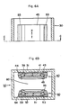
- Fig. 1 (A) is a transverse upper view of a magnetic field generating device according to the present invention for use in the NMR-CT device and Fig. 1 (B) is a sectional view taken along line A-A in Fig. 1 (A).
- the device includes a yoke assembly 30 which is composed of a pair of opposed square plate-like yokes 31 and 32 coupled together by four rod-like yokes 33, on the opposing inner surfaces of the plate-like yokes 31 and 32 being attached permanent magnet assemblies 40 and 50 according to the present invention to create a required air gap 60 therebetween.
- the plate-like yokes 31 and 32 and rod-like yokes 33 of the yoke assembly 30 are assembled into a single body by inserting the rod-like yokes 33 erected at the four corners of the lower plate-like yoke 32 into the holes formed at the four corners of the upper plate-like yoke 31, securing each top-provided cylindrical cover 34 to the margin of the corresponding hole of the upper plate-like yoke 31 by means of bolts 35 so as to cover the corresponding rod-like yoke 33 thus projected, and fixing each cover 34 to the corresponding rod-like yoke 33 by means of fixing bolts 37 provided around an adjusting bolt 36.
- the upper plate-like yoke 31 is mounted on the upper ends of the rod-like yokes 33 via the adjusting bolts 36 each threaded at the center of the corresponding cover 34, thus is movable a little vertically in response to forward/reverse screwing of each adjusting bolt 36, so that its horizontal level or the spacing between it and the lower plate-like yoke 32 can be adjusted.
- the permanent magnet assembly 40, 50 attached to the opposing surface of the upper or lower plate-like yoke 31, 32 with interposition of disk-like yoke 38, 39 having a hole in the center, is composed of a central permanent magnet 41, 51 and peripheral permanent magnets 43, 53.
- Each central permanent magnet 41, 51 is made into the form of an octagonal plate formed at the center with a magnetic force adjusting hole 42, 52, and the eight substantially-trap- ' ezoidal plate-like peripheral permanent magnets 43, 53 are arranged so as to contact with the respective sides of the corresponding central permanent magnet 41, 51 and inclined by means of trapezoidal wedge-like yokes 44, 54, thereby forming an opposing concave face.
- the permanent magnet assembly is configured so that the peripheral permanent magnets are arranged along a substantial circumference of the central permanent magnet and its magnetic pole surface forms a substantially-circular curved concave face.
- the central permanent magnet illustrated is made into the form of an octagonal plate, this magnet may be more polygonal than the octagon so as to assume a shape very similar to a disk, but, such a shape as the illustrated one is deemed to be effective in consideration of the shape, number, assembly work and the like of the peripheral permanent magnets.
- the permanent magnet assembly 40, 50 is made up of a number of block-shaped permanent magnets which are subjected to a magnetizing/assembling process so as to assume the foregoing shape, each having the magnetization direction perpendicular to the magnetic pole surface.
- each permanent magnet assembly 40, 50 having the concave magnetic pole surface formed thereon is attached a magnetic pole segment 45, 55 having a substantially-circular curved concave face, each being made up of an octagonal flat portion, eight trapezoidal inclined portions arranged around the periphery of the flat portion, and a circular projection portion 46, 56 provided on the opposing flat portion, so that there results in the function of concentrating effectively the magnetic flux within the air gap 60 formed between the paired magnetic pole segments 45 and 55.
- each plate-like yoke 31 In the central portion of the non-attached side of each plate-like yoke 31, 32 is bored a so-called tapered hole 70, 71 which communicates with the hole of the disk-like yoke 38, 39, and a magnetic force adjusting member 72 made of rod-like magnetic material to be inserted in the magnetic force adjusting hole 42, 52 of the central permanent magnet 41, 51 is attached to the margin of the hole of the disk-like yoke 38, 39 so that its extent of insertion can be adjusted.
- the tapered hole 70, 71 of the plate-like yoke 31, 32 is bored, taking notice of the fact that the amount of magnetic flux becomes smaller as closing to the central portion of the plate yoke 31, 32, for the purpose of reducing the weight of the yoke assembly and of preventing the magnetic force adjusting members 72 from being exposed externally.
- Adjustment of the uniformity, distribution and the like of the magnetic field can be achieved by means of the adjusting bolts 36 each abutable on the upper end of the corresponding rod-like yoke 33 to adjust the spacing between the permanent magnet assemblies 40 and 50 and of the magnetic field adjusting members 72 each insertable in the central portion of the corresponding permanent magnet assembly 40, 50 to adjust the amount of shunting the flux originating from the central permanent magnet 40, 50, and further by shifting horizontally a little the disk-like yoke 38, 39, or by performing leveling of the permanent magnet assembly 40, 50 by changing the thickness and the like of the corresponding disk-like yoke, or through a combination of these measures.
- disk-like yoke 38, 39 may be made integral with the wedge-like yoke 44, 54.
- the magnetic flux generated by the permanent magnet assemblies 40 and 50 is converged in the same direction as the magnetization direction of the magnet by means of the magnetic pole segments 45 and 55 to create the magnetic field, thus, the amount of leakage flux is reduced and the static magnetic field having a very high degree of uniformity is obtained within the air gap 60.
- the permanent magnet assembly is substantially circular and the peripheral permanent magnets are arranged along the whole periphery of the central permanent magnet, thus, magnetic balance of the system is easily attained, the leakage flux is reduced, and the degree of uniformity of the static magnetic field created in the central portion of the air gap becomes so high as could not be attained by the devices hitherto known.
- Fig. 6(A) is a transverse upper view of another embodiment and Fig. 6(B) is a sectional view taken along line C-C in Fig. 6(B).
- the device illustrated has the configuration convenient in inserting an object to be examined in the direction of the arrow X and subjecting to examination, in which the yoke assembly 30 is made of a quadrangular cylinder-like yoke, and on the inner surfaces of the upper and lower plate-like yokes 31 and 32 are attached the pair of permanent magnet assemblies 40 and 50 with interposition of the rectangular plate-like yokes 38 and 39 so as to create the air gap 60.
- Each permanent magnet assembly 40, 50 comprises the rectangular central permanent magnet 41, 51 and the prismatic peripheral permanent magnets 43, 53 inclined toward the inside of the air gap 60 and attached to the opposed side faces of the central permanent magnet 41, 51 extending parallelly with the insertion direction (the direction of the arrow X ) of an object (not shown ) to be examined, with the wedge-like yokes 44, 54 interposed between the plate-like yoke 38, 39 and the peripheral permanent magnets 43, 53, and the magnetic pole surface of each permanent magnet assembly is made so as to form a substantially groove-like curved concave face with respect to the air gap 60.
- each permanent magnet assembly 40, 50 has the magnetization direction perpendicular to its magnetic pole surface. Further, to each magnetic pole surface is attached the plate-like magnetic pole segment 45, 55 having a substantially groove-like curved concave face.
- the magnetic flux originating from the magnetic pole segments 45 and 55 is converged in the same direction as the magnetization direction of the permanent magnets to create the magnetic field, thus, the leakage flux is reduced and the static magnetic field having a high degree of uniformity is obtained within the air gap 60.
- the device of the foregoing configuration includes, as compared with the device shown in Fig. 1, the peripheral permanent magnets attached only to the opposed side faces of the central permanent magnet, it is rather hard to obtain magnetic balance, but, each permanent magnet can take a relatively simple shape, such as a rectangular shape or prismatic shape, thus, there is the effect that machining, assembling and the like can be performed easily. Further, since no peripheral permanent magnet is arranged at the position of insertion of an object to be examined, the spacing between the paired permanent magnet assemblies can be narrowed, thus, this configuration is advantageous also for the purpose of miniaturization and weight reduction.
- the present invention provides a configuration including a magnetic field adjusting segment as shown in Fig. 7 which serves as magnetic field fine adjustment means.
- FIG. 7 shows the configuration in which at least one magnetic field adjusting segment 58 made of magnetic material is attached to a required spot on the peripheral inclined portion 57 of the magnetic pole segment 55 having the curved concave face which in turn is attached on the magnetic pole surface of the permanent magnet assembly 50 composed of the central permanent magnet 51 and the peripheral permanent magnets 53 (the configuration illustrated includes five metallic disk-like magnetic field adjusting segments attached on each side).
- the shape, dimension, and number of the magnetic field adjusting segments 58 can be determined arbitrarily, and the attached spot of each magnetic field adjusting segment can be anywhere if it is within the peripheral inclined portion 57 of the magnetic pole segment 55 as shown in Rg. 7, but, the foregoing selectable conditions must be determined depending upon the magnetic characteristic of the permanent magnet, as well as the shape, dimension and the like of the permanent magnet assembly 50 and magnetic pole segment 55 so as to create the magnetic field of required uniformity.
- the magnetic field adjusting segment 58 may either be attached after assembly of the device or be previously formed integrally with the peripheral inclined portion 57.
- the permanent magnet assembly includes the effectively arranged central permanent magnet and peripheral permanent magnets and its magnetic pole surface is made into the form of a curved concave face, thus, it becomes possible to reduce remarkably the amount of the flux leaking out of the air gap, the excellently accurate, uniform, stable magnetic field can be created within the air gap, and miniaturization and weight reduction of the device can be attained.
- the magnetic field generating device of the present invention shown in Fig. 1 was assembled using Fe-B-R series permanent magnet having a maximum energy product of 35 MGOe as the central permanent magnet and peripheral permanent magnets and setting the spacing between the magnetic pole segments to 570 mm.
- the magnetic field strength obtained in the central portion of the air gap was 1.5 kG
- the uniformity of the magnetic field within the range of 300 mmDSV was less than 40 ppm
- the weight of the permanent magnet assembly was 1.1 tons.
- the conventional device of the configuration shown in Fig. 8 was also manufactured using permanent magnets of an equivalent composition and magnetic characteristic to the above. It needed the permanent magnet of 1.5 tons to get a similar uniform magnetic field area and magnetic field strength to the foregoing example of the present invention.
Landscapes
- Physics & Mathematics (AREA)
- Condensed Matter Physics & Semiconductors (AREA)
- General Physics & Mathematics (AREA)
- Electromagnetism (AREA)
- Engineering & Computer Science (AREA)
- Power Engineering (AREA)
- Magnetic Resonance Imaging Apparatus (AREA)
Claims (13)
Applications Claiming Priority (4)
| Application Number | Priority Date | Filing Date | Title |
|---|---|---|---|
| JP20354985U JPH0244485Y2 (fr) | 1985-12-27 | 1985-12-27 | |
| JP203549/85 | 1985-12-27 | ||
| JP99938/86 | 1986-04-30 | ||
| JP61099938A JPS62256416A (ja) | 1986-04-30 | 1986-04-30 | 磁界発生装置 |
Publications (3)
| Publication Number | Publication Date |
|---|---|
| EP0228154A2 EP0228154A2 (fr) | 1987-07-08 |
| EP0228154A3 EP0228154A3 (en) | 1988-07-20 |
| EP0228154B1 true EP0228154B1 (fr) | 1990-12-05 |
Family
ID=26441028
Family Applications (1)
| Application Number | Title | Priority Date | Filing Date |
|---|---|---|---|
| EP86307272A Expired EP0228154B1 (fr) | 1985-12-27 | 1986-09-22 | Dispositif de génération du champ magnétique pour tomographie par RMN |
Country Status (3)
| Country | Link |
|---|---|
| US (1) | US4679022A (fr) |
| EP (1) | EP0228154B1 (fr) |
| DE (1) | DE3676066D1 (fr) |
Families Citing this family (55)
| Publication number | Priority date | Publication date | Assignee | Title |
|---|---|---|---|---|
| US5063934A (en) * | 1987-10-07 | 1991-11-12 | Advanced Techtronics, Inc. | Permanent magnet arrangement |
| US4998976A (en) * | 1987-10-07 | 1991-03-12 | Uri Rapoport | Permanent magnet arrangement |
| DE3737133A1 (de) * | 1987-11-02 | 1989-05-11 | Siemens Ag | Homogenfeldmagnet mit profilierten polplatten |
| GB2215522B (en) * | 1988-02-26 | 1990-11-28 | Picker Int Ltd | Magnet arrangements |
| US5080731A (en) * | 1988-08-19 | 1992-01-14 | Hitachi Metals, Ltd. | Highly oriented permanent magnet and process for producing the same |
| US5097240A (en) * | 1989-06-16 | 1992-03-17 | Sumitomo Special Metal Co., Ltd. | Magnetic field generating device for esr system |
| JPH03131234A (ja) * | 1989-07-07 | 1991-06-04 | Sumitomo Special Metals Co Ltd | Mri用磁界発生装置 |
| US5049848A (en) * | 1989-11-28 | 1991-09-17 | Pulyer Yuly M | High field strength magnet, preferably having remote shimming of field |
| US5152711A (en) * | 1990-05-23 | 1992-10-06 | Louis Gross | Magnetic toy having sculpturable particles |
| US5124651A (en) * | 1990-10-24 | 1992-06-23 | Fonar Corporation | Nuclear magnetic resonance scanners with composite pole facings |
| US5117188A (en) * | 1990-10-29 | 1992-05-26 | General Atomics | Quasi-open magnet configuration for use in magnetic resonance imaging |
| EP0488015B1 (fr) * | 1990-11-30 | 1996-10-30 | Siemens Aktiengesellschaft | Aimant pour champ homogène avec au moins une pièce polaire ajustable mécaniquement |
| JPH067316A (ja) * | 1992-06-29 | 1994-01-18 | Hitachi Medical Corp | 磁気共鳴イメージング装置の磁界発生装置 |
| IL106779A0 (en) * | 1992-09-11 | 1993-12-08 | Magna Lab Inc | Permanent magnetic structure |
| US5754085A (en) * | 1992-09-28 | 1998-05-19 | Fonar Corporation | Ferromagnetic yoke magnets for medical magnetic resonance studies |
| US6335623B1 (en) | 1992-12-18 | 2002-01-01 | Fonar Corporation | MRI apparatus |
| US5389879A (en) * | 1992-12-18 | 1995-02-14 | Pulyer; Yuly M. | MRI device having high field strength cylindrical magnet with two axially spaced electromagnets |
| US6201394B1 (en) | 1992-12-18 | 2001-03-13 | Fonar Corporation | MRI apparatus |
| JP3266355B2 (ja) * | 1993-02-05 | 2002-03-18 | 住友特殊金属株式会社 | 超電導型mri用磁界発生装置 |
| JP2757104B2 (ja) * | 1993-04-01 | 1998-05-25 | 信越化学工業株式会社 | 磁場発生装置 |
| US5495222A (en) * | 1994-04-15 | 1996-02-27 | New York University | Open permanent magnet structure for generating highly uniform field |
| DE69738995D1 (de) | 1996-10-30 | 2008-10-30 | Hitachi Medical Corp | Supraleitende magnetfelderzeugende einrichtung |
| NO305270B1 (no) * | 1997-12-04 | 1999-04-26 | Seas Fabrikker As | Permanentmagnetmontasje |
| US7127802B1 (en) | 1997-11-21 | 2006-10-31 | Fonar Corporation | Method of fabricating a composite plate |
| US6437571B1 (en) | 1997-11-21 | 2002-08-20 | Fonar Corporation | MRI apparatus |
| WO1999040593A1 (fr) * | 1998-02-09 | 1999-08-12 | Odin Medical Technologies Ltd | Conception d'aimants ouverts et dispositif a aimants ouverts destine aux sondes d'imagerie/traitement par resonance magnetique |
| US6265959B1 (en) * | 1998-04-29 | 2001-07-24 | New York University | Open unipolar magnetic structure |
| JP2000139874A (ja) | 1998-09-02 | 2000-05-23 | Sumitomo Special Metals Co Ltd | Mri用磁界発生装置 |
| USD428151S (en) * | 1998-11-25 | 2000-07-11 | Fonar Corporation | Magnetic resonance imaging apparatus |
| KR100319923B1 (ko) | 1999-05-10 | 2002-01-09 | 윤종용 | 자기공명영상장치용 자기장 발생 장치 |
| EP1069575B1 (fr) * | 1999-07-15 | 2008-05-14 | Neomax Co., Ltd. | Procédé de démontage pour générateur de champ magnétique |
| EP1666910B1 (fr) * | 1999-11-16 | 2009-03-11 | Hitachi Metals, Ltd. | Générateur de champ magnétique comportant une unité de pièce polaire |
| CN100360084C (zh) * | 1999-11-16 | 2008-01-09 | 株式会社新王磁材 | 磁场发生器 |
| WO2001055732A2 (fr) * | 2000-01-25 | 2001-08-02 | Uri Rapoport | Mecanismes de reglage du champ et procedes permettant l'agencement d'un aimant permanent au moyen d'une plaque d'appui |
| US6822449B1 (en) | 2000-11-22 | 2004-11-23 | Fonar Corporation | Ferromagnetic frame with laminated carbon steel |
| US6662434B2 (en) | 2001-04-03 | 2003-12-16 | General Electric Company | Method and apparatus for magnetizing a permanent magnet |
| US6518867B2 (en) | 2001-04-03 | 2003-02-11 | General Electric Company | Permanent magnet assembly and method of making thereof |
| US7906966B1 (en) | 2001-10-05 | 2011-03-15 | Fonar Corporation | Quadrature foot coil antenna for magnetic resonance imaging |
| US7701209B1 (en) | 2001-10-05 | 2010-04-20 | Fonar Corporation | Coils for horizontal field magnetic resonance imaging |
| DE10224192A1 (de) | 2002-05-31 | 2003-12-18 | Fraunhofer Ges Forschung | Bildgebendes NMR-Verfahren sowie NMR-Vorrichtung |
| US8064984B2 (en) | 2003-03-18 | 2011-11-22 | Esaote S.P.A. | Magnetic resonance imaging apparatus |
| US7423431B2 (en) * | 2003-09-29 | 2008-09-09 | General Electric Company | Multiple ring polefaceless permanent magnet and method of making |
| US7148689B2 (en) | 2003-09-29 | 2006-12-12 | General Electric Company | Permanent magnet assembly with movable permanent body for main magnetic field adjustable |
| CN100350522C (zh) * | 2004-05-18 | 2007-11-21 | 北京泰杰磁电研究所 | 一种磁共振成像磁体及构成方法 |
| JP3992694B2 (ja) * | 2004-05-24 | 2007-10-17 | ジーイー・メディカル・システムズ・グローバル・テクノロジー・カンパニー・エルエルシー | Mri装置 |
| US7796002B2 (en) * | 2004-09-30 | 2010-09-14 | Hitachi Metals, Ltd. | Magnetic field generator for MRI |
| US8401615B1 (en) | 2004-11-12 | 2013-03-19 | Fonar Corporation | Planar coil flexion fixture for magnetic resonance imaging and use thereof |
| US9386939B1 (en) | 2007-05-10 | 2016-07-12 | Fonar Corporation | Magnetic resonance imaging of the spine to detect scoliosis |
| JP2008312056A (ja) * | 2007-06-15 | 2008-12-25 | Citizen Electronics Co Ltd | 電気音響変換器 |
| JP5012572B2 (ja) * | 2008-02-29 | 2012-08-29 | 富士通株式会社 | マグネトロンスパッタ装置用磁石ユニット |
| US20110175694A1 (en) | 2008-06-24 | 2011-07-21 | Fallone B Gino | Magnetic assembly and method for defining a magnetic field for an imaging volume |
| CN104094368A (zh) * | 2012-01-30 | 2014-10-08 | 三菱电机株式会社 | 磁路 |
| US11141080B1 (en) | 2013-03-13 | 2021-10-12 | Fonar Corporation | Cervical vertebra angle measurement |
| US11075027B1 (en) * | 2018-07-03 | 2021-07-27 | Q Magnetics, LLC | Permanent magnet for generating homogenous and intense magnetic field |
| EP4231034A1 (fr) * | 2022-02-16 | 2023-08-23 | Siemens Healthcare GmbH | Dispositif de résonance magnétique dédié |
Family Cites Families (9)
| Publication number | Priority date | Publication date | Assignee | Title |
|---|---|---|---|---|
| GB1110172A (en) * | 1964-04-22 | 1968-04-18 | Newport Instr Ltd | Improvements in or relating to magnet structures |
| CA1198162A (fr) * | 1982-09-23 | 1985-12-17 | Robert D. Hay | Appareil de visualisation a resonnance magnetique nucleaire |
| US4580098A (en) * | 1983-05-02 | 1986-04-01 | E. I. Du Pont De Nemours And Company | Permanent magnet NMR imaging apparatus |
| JPS6021084A (ja) * | 1983-07-15 | 1985-02-02 | 富士通株式会社 | 立体表示装置 |
| DE3566185D1 (en) * | 1984-04-11 | 1988-12-15 | Sumitomo Spec Metals | Magnetic field generating device for nmr-ct |
| US4538130A (en) * | 1984-04-23 | 1985-08-27 | Field Effects, Inc. | Tunable segmented ring magnet and method of manufacture |
| NL8402250A (nl) * | 1984-07-17 | 1986-02-17 | Philips Nv | Kernspin resonantie apparaat met een rechthoekig permanent magnetische magneet. |
| US4647887A (en) * | 1984-12-24 | 1987-03-03 | The United States Of America As Represented By The Secretary Of The Army | Lightweight cladding for magnetic circuits |
| JPS61115958U (fr) * | 1984-12-30 | 1986-07-22 |
-
1986
- 1986-09-19 US US06/909,327 patent/US4679022A/en not_active Expired - Lifetime
- 1986-09-22 EP EP86307272A patent/EP0228154B1/fr not_active Expired
- 1986-09-22 DE DE8686307272T patent/DE3676066D1/de not_active Expired - Lifetime
Also Published As
| Publication number | Publication date |
|---|---|
| EP0228154A3 (en) | 1988-07-20 |
| DE3676066D1 (de) | 1991-01-17 |
| US4679022A (en) | 1987-07-07 |
| EP0228154A2 (fr) | 1987-07-08 |
Similar Documents
| Publication | Publication Date | Title |
|---|---|---|
| EP0228154B1 (fr) | Dispositif de génération du champ magnétique pour tomographie par RMN | |
| US4777464A (en) | Magnetic field generating device for NMR-CT | |
| US4818966A (en) | Magnetic field generating device | |
| EP0161782B1 (fr) | Dispositif pour la génération d'un champ magnétique pour NMR-CT | |
| US5229723A (en) | Magnetic field generating device for mri | |
| US5886609A (en) | Single dipole permanent magnet structure with linear gradient magnetic field intensity | |
| US4549155A (en) | Permanent magnet multipole with adjustable strength | |
| US4707663A (en) | Nuclear magnetic resonance apparatus using low energy magnetic elements | |
| US5283544A (en) | Magnetic field generating device used for MRI | |
| US5596304A (en) | Permanent magnet edge-field quadrupole | |
| KR900008082B1 (en) | Operating apparatus for objective lens | |
| US3437963A (en) | Permanent magnet having an enclosing yoke structure with pole aligning means | |
| EP0941019B1 (fr) | Wiggler hybride | |
| US4761584A (en) | Strong permanent magnet-assisted electromagnetic undulator | |
| US5939964A (en) | Compact magnetic module for periodic magnetic devices | |
| CA2110289A1 (fr) | Aimants permanents hydrides | |
| JPH0320053B2 (fr) | ||
| JPH0345886B2 (fr) | ||
| US3681599A (en) | Sector-type charged particle energy analyzer | |
| JPH0541530Y2 (fr) | ||
| JP3059596B2 (ja) | Mri用磁界発生装置 | |
| JPH02184003A (ja) | Mri用磁界発生装置 | |
| JPH0563085B2 (fr) | ||
| JPH0244485Y2 (fr) | ||
| JPH09117431A (ja) | Mri用磁界発生装置 |
Legal Events
| Date | Code | Title | Description |
|---|---|---|---|
| PUAI | Public reference made under article 153(3) epc to a published international application that has entered the european phase |
Free format text: ORIGINAL CODE: 0009012 |
|
| AK | Designated contracting states |
Kind code of ref document: A2 Designated state(s): DE FR GB IT NL |
|
| PUAL | Search report despatched |
Free format text: ORIGINAL CODE: 0009013 |
|
| AK | Designated contracting states |
Kind code of ref document: A3 Designated state(s): DE FR GB IT NL |
|
| 17P | Request for examination filed |
Effective date: 19881221 |
|
| 17Q | First examination report despatched |
Effective date: 19900514 |
|
| GRAA | (expected) grant |
Free format text: ORIGINAL CODE: 0009210 |
|
| AK | Designated contracting states |
Kind code of ref document: B1 Designated state(s): DE FR GB IT NL |
|
| ITF | It: translation for a ep patent filed | ||
| REF | Corresponds to: |
Ref document number: 3676066 Country of ref document: DE Date of ref document: 19910117 |
|
| ET | Fr: translation filed | ||
| PLBE | No opposition filed within time limit |
Free format text: ORIGINAL CODE: 0009261 |
|
| STAA | Information on the status of an ep patent application or granted ep patent |
Free format text: STATUS: NO OPPOSITION FILED WITHIN TIME LIMIT |
|
| 26N | No opposition filed | ||
| ITTA | It: last paid annual fee | ||
| REG | Reference to a national code |
Ref country code: GB Ref legal event code: IF02 |
|
| PGFP | Annual fee paid to national office [announced via postgrant information from national office to epo] |
Ref country code: FR Payment date: 20050831 Year of fee payment: 20 |
|
| PGFP | Annual fee paid to national office [announced via postgrant information from national office to epo] |
Ref country code: GB Payment date: 20050906 Year of fee payment: 20 |
|
| PGFP | Annual fee paid to national office [announced via postgrant information from national office to epo] |
Ref country code: IT Payment date: 20050927 Year of fee payment: 20 |
|
| PGFP | Annual fee paid to national office [announced via postgrant information from national office to epo] |
Ref country code: NL Payment date: 20050929 Year of fee payment: 20 |
|
| PGFP | Annual fee paid to national office [announced via postgrant information from national office to epo] |
Ref country code: DE Payment date: 20051012 Year of fee payment: 20 |
|
| PG25 | Lapsed in a contracting state [announced via postgrant information from national office to epo] |
Ref country code: GB Free format text: LAPSE BECAUSE OF EXPIRATION OF PROTECTION Effective date: 20060921 |
|
| PG25 | Lapsed in a contracting state [announced via postgrant information from national office to epo] |
Ref country code: NL Free format text: LAPSE BECAUSE OF EXPIRATION OF PROTECTION Effective date: 20060922 |
|
| REG | Reference to a national code |
Ref country code: GB Ref legal event code: PE20 |
|
| NLV7 | Nl: ceased due to reaching the maximum lifetime of a patent |
Effective date: 20060922 |