EP0228227B1 - Dispositif pour pousser une pièce mobile axialement vers une position axiale neutre - Google Patents
Dispositif pour pousser une pièce mobile axialement vers une position axiale neutre Download PDFInfo
- Publication number
- EP0228227B1 EP0228227B1 EP86309764A EP86309764A EP0228227B1 EP 0228227 B1 EP0228227 B1 EP 0228227B1 EP 86309764 A EP86309764 A EP 86309764A EP 86309764 A EP86309764 A EP 86309764A EP 0228227 B1 EP0228227 B1 EP 0228227B1
- Authority
- EP
- European Patent Office
- Prior art keywords
- axially movable
- movable member
- magnetic
- yoke
- axial position
- Prior art date
- Legal status (The legal status is an assumption and is not a legal conclusion. Google has not performed a legal analysis and makes no representation as to the accuracy of the status listed.)
- Expired
Links
Images




Classifications
-
- H—ELECTRICITY
- H02—GENERATION; CONVERSION OR DISTRIBUTION OF ELECTRIC POWER
- H02K—DYNAMO-ELECTRIC MACHINES
- H02K49/00—Dynamo-electric clutches; Dynamo-electric brakes
-
- G—PHYSICS
- G11—INFORMATION STORAGE
- G11B—INFORMATION STORAGE BASED ON RELATIVE MOVEMENT BETWEEN RECORD CARRIER AND TRANSDUCER
- G11B7/00—Recording or reproducing by optical means, e.g. recording using a thermal beam of optical radiation by modifying optical properties or the physical structure, reproducing using an optical beam at lower power by sensing optical properties; Record carriers therefor
- G11B7/08—Disposition or mounting of heads or light sources relatively to record carriers
- G11B7/09—Disposition or mounting of heads or light sources relatively to record carriers with provision for moving the light beam or focus plane for the purpose of maintaining alignment of the light beam relative to the record carrier during transducing operation, e.g. to compensate for surface irregularities of the latter or for track following
- G11B7/0925—Electromechanical actuators for lens positioning
- G11B7/0935—Details of the moving parts
-
- H—ELECTRICITY
- H02—GENERATION; CONVERSION OR DISTRIBUTION OF ELECTRIC POWER
- H02K—DYNAMO-ELECTRIC MACHINES
- H02K41/00—Propulsion systems in which a rigid body is moved along a path due to dynamo-electric interaction between the body and a magnetic field travelling along the path
- H02K41/02—Linear motors; Sectional motors
- H02K41/035—DC motors; Unipolar motors
- H02K41/0352—Unipolar motors
- H02K41/0354—Lorentz force motors, e.g. voice coil motors
-
- H—ELECTRICITY
- H02—GENERATION; CONVERSION OR DISTRIBUTION OF ELECTRIC POWER
- H02K—DYNAMO-ELECTRIC MACHINES
- H02K2201/00—Specific aspects not provided for in the other groups of this subclass relating to the magnetic circuits
- H02K2201/18—Machines moving with multiple degrees of freedom
-
- Y—GENERAL TAGGING OF NEW TECHNOLOGICAL DEVELOPMENTS; GENERAL TAGGING OF CROSS-SECTIONAL TECHNOLOGIES SPANNING OVER SEVERAL SECTIONS OF THE IPC; TECHNICAL SUBJECTS COVERED BY FORMER USPC CROSS-REFERENCE ART COLLECTIONS [XRACs] AND DIGESTS
- Y10—TECHNICAL SUBJECTS COVERED BY FORMER USPC
- Y10S—TECHNICAL SUBJECTS COVERED BY FORMER USPC CROSS-REFERENCE ART COLLECTIONS [XRACs] AND DIGESTS
- Y10S359/00—Optical: systems and elements
- Y10S359/903—Optical: systems and elements with magnet
Definitions
- This invention relates to apparatus for urging an axially movable member to a neutral axial position and it relates more particularly to such apparatus when used in an optical pickup so as to retain the neutral point of focusing in equipment in which focusing and tracking are performed by sliding a lens in the axial direction and by rotating it about a shaft, respectively.
- An optical pickup in which focusing and tracking are performed by sliding a lens in the axial direction and by rotating it about a shaft, respectively.
- a rubber spring as a focusing spring.
- the rubber spring does not have good temperature characteristics due to the physical properties of its material, and it deteriorates as its resonance frequency or sensitivity changes.
- JP-A-59-229,750 there is disclosed an apparatus for urging an axially movable member towards a neutral axial position comprising an axially movable member which is axially movable over a shaft; coil means mounted on the axially movable member for adjusting the axial position of the latter; and magnetic circuit means for generating a magnetic field in which the coil means is positioned, the axially movable member being provided with pieces of magnetic material which are disposed in said magnetic field so that the latter exerts a force which urges the axially movable member towards a neutral axial position.
- apparatus for urging an axially movable member towards a neutral axial position comprising an axially movable member which is axially movable over a shaft; coil means mounted on the axially movable member for adjusting the axial position of the latter; and magnetic circuit means for generating a magnetic field in which the coil means is positioned, the axially movable member being provided with pieces of magnetic material which are disposed in said magnetic field so that the latter exerts a force which urges the axially movable member towards a neutral axial position, characterised in that the pieces of magnetic material are disposed adjacent axially opposite ends of the axially movable member so that there is a substantially linear relationship between the said force and the movement of the axially movable member.
- the magnetic circuit means may comprise one or more permanent magnets and one or more yokes of magnetically permeable material, the yoke or yokes being disposed radially inwardly and/or radially outwardly of the axially movable member.
- the yoke or yokes may be disposed radially inwardly and/or radially outwardly of the axially movable member.
- there may be both an inner yoke and an outer yoke or, alternatively, one single yoke may be provided.
- the or each magnet is disposed between a said yoke and the axially movable member.
- the said member is both axially movable and rotatable, the said member carrying an objective lens which is radially spaced from the shaft, the said member being provided with tracking means for moving the said member circumferentially so as to effect tracking of the objective lens.
- the apparatus of the present invention thus requires no space for a spring to be used for focusing, is easily manufactured, and exhibits excellent temperature characteristics, thereby overcoming the problems of the known apparatus referred to above.
- the present invention is based on the principle that a piece of magnetic material, when placed in a magnetic field which has non-uniform magnetic field distribution, is subjected to a force acting in the direction in which the potential energy of the piece of magnetic material becomes stable, and utilizes this force as a spring force employed for focusing.
- a number of pieces of magnetic material are attached to the peripheral portion of an objective lens retaining holder such that they are disposed at the centre or near the ends of two magnetic gaps as viewed in the axial direction.
- the magnetic gaps form a magnetic field in which the magnetic flux density is at a maximum at the centre and gradually decreases farther from the centre owing to leakage flux.
- the objective lens retaining holder slides in the focusing (i.e. the axial) direction and the pieces of magnetic material are located apart from the centre, they are subjected to a force which tends to pull them back into the magnetic gaps. This force constitutes a magnetic spring force in the focusing direction.
- an objective lens retaining holder 1 has a tubular portion 1a and a diametrically extending arm 1b which extends radially outwardly of the tubular portion 1a on diametrically opposite sides of the latter.
- the arm 1b is provided with an objective lens 2.
- the tubular portion 1a is provided with a focusing coil 3 for adjusting focusing, tracking coils 4 for adjusting tracking, and two pieces of magnetically permeable material 11, e.g. unmagnetised iron or nickel.
- the holder 1 can be rotated about a supporting shaft 7 and can be slid in the axial direction of the supporting shaft 7.
- the objective lens 2 is radially spaced from the shaft 7.
- the focusing coil 3 and the tracking coils 4 are mounted on the outer surface of the tubular portion 1a and are insulated from each other.
- An outer yoke 8 of magnetically permeable material has a plate 8a which is mounted beneath the holder 1.
- the outer yoke 8 has two spaced apart blocks 8b which are mounted on or integral with the plate 8a and each of which is disposed radially outwardly of and is spaced from the tubular portion 1a.
- An inner yoke 5 of magnetically permeable material comprises two spaced apart blocks 5a which are mounted on or are integral with the plate 8a.
- the blocks 5a are respectively disposed within slots 1c in the holder 1, the slots 1c being formed between the tubular portion 1a and the arm 1b.
- the blocks 5a are radially spaced from the tubular portion 1a.
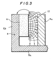
- Each of the blocks 8b of the outer yoke 8 carries on its radially inner side a permanent magnet 6 which, as shown in Figure 3, is radially spaced from the respective block 5a of the inner yoke 5 so as to provide a space 12 therebetween.
- the tubular portion 1a is mounted in the space 12 so as to provide an outer magnetic gap 13 ( Figure 4) between the magnets 6 and the tubular portion 1a and an inner magnetic gap 14 ( Figure 4) between the blocks 5a and the tubular portion 1a, the pieces of magnetic material 11 being disposed within the outer magnetic gap 13.
- Figure 3 shows the magnetic field distribution in the space 12.
- the lines with arrows adjacent one end thereof indicate lines of magnetic force.
- the density of these lines of magnetic force represents the intensity of the magnetic field. Points of equal magnetic field intensity are connected with solid lines to show the magnetic field distribution.
- the magnetic flux density is at a maximum at the centre and decreases as it goes away from the centre due to leakage flux, as can be seen in Figure 3.
- the apparatus shown in Figure 4 has two pieces of magnetic material 11 which are respectively provided at the upper and lower ends of the outer magnetic gap 13. This provides a magnetic spring for use in focusing which has further linear characteristics.
- the pieces of magnetic material 11 are respectively disposed at positions at which they are subjected to substantially equal and opposite magnetic forces acting in the axial direction when the objective lens retaining holder 1 is in the neutral axial position.
- they may be disposed adjacent axially opposite ends of the objective lens retaining holder 1.
- Figures 5a and 5b are graphs illustrating how the spring force is made linear by providing the pieces of magnetic material 11 at the upper and lower ends of the outer magnetic gap 13.
- the spring force FA shows non-linear characteristics, strictly speaking, if a single piece of magnetic material 11 were to be provided only at the centre of the outer magnetic gap 13.
- a linear spring force Fc for focusing such as the one shown by the solid line in Figure 5b, is, however, available when the magnetic spring forces provided by the two pieces of magnetic material 11 mounted at the upper and lower ends of the outer magnetic gap 13, which are shown in Figure 5b by broken lines Fu and chain lines F1 respectively, are combined.
- the vertical axis F relates to the magnetic spring force in the focusing direction
- the horizontal axis X relates to the position of the tubular portion 1a in the focusing direction.
- Figure 6 is a perspective view of an apparatus according to the present invention with pieces of magnetic material 11 provided at the upper and lower ends of the outer magnetic gap 13. Figure 6 will not be described in detail since it is generally similar to Figure 1.
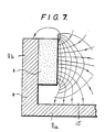
- FIG. 7 is a side cross-sectional view illustrating the magnetic field distribution in a magnetic gap 15 in this case.
- the lines with arrows provided adjacent one end thereof indicate lines of magnetic force.
- the solid lines connect the points of equal intensity of the magnetic field.
- the embodiments of the invention shown in the drawings employ pieces of magnetic material 11 having a rectangular configuration.
- the pieces of magnetic material 11 may be round in shape, or may be shaped in the form of a ring which can be fitted or attached to the objective lens retaining holder 1. They may also be shaped into rectangles which have longer sides in the axial direction, or into arcuate members having longer sides of the circumferential than in the axial direction.
- Figure 0 is a graph illustrating the frequency characteristics obtained in an apparatus in accordance with any of the embodiments mentioned above. This graph shows that no harmonics of vibrations are generated and that excellent spring characteristics are available.
- a magnetic spring for use in focusing can be provided simply by attaching pieces of magnetic material 11 to opposite ends of the objective lens retaining holder 1.
- the space required for the rubber spring in the known apparatus can be eliminated, thereby contributing to a reduction in the size of the apparatus.
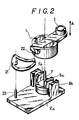
- FIG. 2 there is shown a known optical pick-up in which focusing and tracking are performed by sliding a lens in the axial direction and by rotating it about a shaft respectively.
- one end of a rubber spring 21 is fixed to a pin 23 which is set in a fixed portion of the apparatus such as a yoke, and the other end of the rubber spring 21 is fixed through a pin 22 to the objective lens retaining holder 1 which constitutes a movable portion.
- the objective lens moves in the focusing direction indicated by A, the objective lens 2 is retained in a given axial position by the resilient force of the rubber spring 21, thereby maintaining the focusing staiblity.
- the magnetic spring employed in the present invention since the magnetic spring employed in the present invention, moreover, utilizes a magnetic action, it has excellent temperature characteristics, compared with the known rubber spring.
Landscapes
- Engineering & Computer Science (AREA)
- Power Engineering (AREA)
- Physics & Mathematics (AREA)
- Chemical & Material Sciences (AREA)
- Combustion & Propulsion (AREA)
- Electromagnetism (AREA)
- Optical Recording Or Reproduction (AREA)
Claims (6)
- Dispositif pour solliciter une pièce mobile en direction axiale vers une position axiale neutre, ce dispositif comprenant une pièce mobile en direction axiale (1) qui peut être déplacée axialement sur un axe (7); une bobine (3) montée sur la pièce mobile en direction axiale (1) pour régler la position axiale de cette dernière; et un circuit magnétique (5, 6, 8) destiné à produire un champ magnétique dans lequel la bobine (3) est placée, la pièce mobile en direction axiale (1) comportant des éléments en matériau magnétique (11) qui sont disposés dans le champ magnétique, de façon que ce dernier exerce une force qui sollicite la pièce mobile en direction axiale (1) vers une position axiale neutre, le dispositif étant caractérisé en ce que les éléments en matériau magnétique (11) sont disposés dans des positions adjacentes aux extrémités opposées en direction axiale de la pièce mobile en direction axiale (1), de façon qu'il y ait une relation pratiquement linéaire (Fc) entre la force précitée et le mouvement de la pièce mobile en direction axiale.
- Dispositif selon la revendication 1, caractérisé en ce que le circuit magnétique (5, 6, 8) comprend un ou plusieurs aimants permanents (6) et une ou plusieurs culasses (5, 8) en un matériau à perméabilité magnétique élevée, la culasse ou les culasses étant disposées radialement du côté intérieur et/ou du côté extérieur de la pièce mobile en direction axiale (1).
- Dispositif selon la revendication 2, caractérisé en ce qu'il comporte à la fois une culasse intérieure (5) et une culasse extérieure (8).
- Dispositif selon la revendication 2, caractérisé en ce qu'il comporte une seule culasse (5, 8).
- Dispositif selon l'une quelconque des revendications 2-4, caractérisé en ce que l'aimant ou chaque aimant (6) est placé entre l'une des culasses précitées (5, 8) et la pièce mobile en direction axiale (1).
- Dispositif selon l'une quelconque des revendications précédentes, caractérisé en ce que la pièce précitée (1) est à la fois mobile en direction axiale et en rotation, cette pièce porte un objectif optique (2) qui est placé à une certaine distance radiale de l'axe (7), et cette pièce (1) comporte des moyens de poursuite (4) qui sont destinés à déplacer la pièce (1) en rotation pour faire en sorte que l'objectif optique (2) effectue un mouvement de poursuite.
Applications Claiming Priority (2)
| Application Number | Priority Date | Filing Date | Title |
|---|---|---|---|
| JP60283735A JPS62141646A (ja) | 1985-12-17 | 1985-12-17 | 対物レンズ駆動装置 |
| JP283735/85 | 1985-12-17 |
Publications (3)
| Publication Number | Publication Date |
|---|---|
| EP0228227A2 EP0228227A2 (fr) | 1987-07-08 |
| EP0228227A3 EP0228227A3 (en) | 1988-03-30 |
| EP0228227B1 true EP0228227B1 (fr) | 1991-10-09 |
Family
ID=17669422
Family Applications (1)
| Application Number | Title | Priority Date | Filing Date |
|---|---|---|---|
| EP86309764A Expired EP0228227B1 (fr) | 1985-12-17 | 1986-12-15 | Dispositif pour pousser une pièce mobile axialement vers une position axiale neutre |
Country Status (4)
| Country | Link |
|---|---|
| US (1) | US4790628A (fr) |
| EP (1) | EP0228227B1 (fr) |
| JP (1) | JPS62141646A (fr) |
| DE (1) | DE3681902D1 (fr) |
Families Citing this family (16)
| Publication number | Priority date | Publication date | Assignee | Title |
|---|---|---|---|---|
| JPH0750528B2 (ja) * | 1987-06-25 | 1995-05-31 | 三菱電機株式会社 | 対物レンズ駆動装置 |
| US5107372A (en) * | 1989-09-06 | 1992-04-21 | Daniel Gelbart | Focus servo actuator for moving lens scanners |
| US5319497A (en) * | 1990-01-12 | 1994-06-07 | Matsushita Electric Industrial Co., Ltd. | Lens drive device with lens holder carrying drive flux generating magnets |
| US5046819A (en) * | 1990-04-16 | 1991-09-10 | International Business Machines Corporation | Objective lens support having rotary and axial motions for use in an optical disk apparatus |
| KR920015291A (ko) * | 1991-01-31 | 1992-08-26 | 강진구 | 광학기록 및 재생장치의 대물렌즈 구동수단 |
| US5146126A (en) * | 1991-09-05 | 1992-09-08 | Hr Textron Inc. | Adjustable rotor assembly |
| JPH05258325A (ja) * | 1992-01-13 | 1993-10-08 | Sharp Corp | 対物レンズ駆動装置 |
| DE4243067C2 (de) * | 1992-01-13 | 2000-12-07 | Sharp Kk | Antriebsvorrichtung für eine Objektivlinse |
| JP2984526B2 (ja) * | 1993-08-31 | 1999-11-29 | 日本電気株式会社 | 光ピックアップ装置 |
| CN1056702C (zh) * | 1993-10-13 | 2000-09-20 | 株式会社三协精机制作所 | 物镜驱动装置 |
| JP2866584B2 (ja) * | 1994-06-28 | 1999-03-08 | 株式会社三協精機製作所 | 対物レンズ駆動装置 |
| JPH0815590A (ja) * | 1994-06-29 | 1996-01-19 | Olympus Optical Co Ltd | 光学要素位置決め装置 |
| DE69634616T2 (de) * | 1995-02-20 | 2006-03-02 | Mitsubishi Denki K.K. | Objektivlinsenantriebsvorrichtung und optische Informationsaufzeichnungs-/-wiedergabevorrichtung |
| JPH09153229A (ja) * | 1995-11-30 | 1997-06-10 | Nec Corp | 光ヘッド装置 |
| KR100298825B1 (ko) * | 1996-08-19 | 2001-10-26 | 하시모토 야스고로 | 대물 렌즈 구동 장치 및 이를 이용한 광디스크 장치 |
| JP3667704B2 (ja) * | 2002-03-22 | 2005-07-06 | 三菱電機株式会社 | 光学素子駆動装置及び光ディスク装置 |
Family Cites Families (6)
| Publication number | Priority date | Publication date | Assignee | Title |
|---|---|---|---|---|
| JPS57210456A (en) * | 1981-06-22 | 1982-12-24 | Sony Corp | Objective lens device |
| US4553227A (en) * | 1982-04-23 | 1985-11-12 | Tokyo Shibaura Denki Kabushiki Kaisha | Optical pickup |
| JPS58163908U (ja) * | 1982-04-27 | 1983-11-01 | 株式会社三協精機製作所 | 対物レンズ駆動装置 |
| JPS59104735A (ja) * | 1982-12-08 | 1984-06-16 | Sony Corp | 対物レンズ駆動装置 |
| CA1249744A (fr) * | 1983-08-03 | 1989-02-07 | Mitsuru Takashima | Capteur optique a unite d'entrainement |
| JPH0731814B2 (ja) * | 1983-12-28 | 1995-04-10 | 株式会社東芝 | 対物レンズ駆動装置 |
-
1985
- 1985-12-17 JP JP60283735A patent/JPS62141646A/ja active Pending
-
1986
- 1986-12-03 US US06/937,603 patent/US4790628A/en not_active Expired - Lifetime
- 1986-12-15 EP EP86309764A patent/EP0228227B1/fr not_active Expired
- 1986-12-15 DE DE8686309764T patent/DE3681902D1/de not_active Expired - Fee Related
Also Published As
| Publication number | Publication date |
|---|---|
| US4790628A (en) | 1988-12-13 |
| EP0228227A2 (fr) | 1987-07-08 |
| DE3681902D1 (de) | 1991-11-14 |
| JPS62141646A (ja) | 1987-06-25 |
| EP0228227A3 (en) | 1988-03-30 |
Similar Documents
| Publication | Publication Date | Title |
|---|---|---|
| EP0228227B1 (fr) | Dispositif pour pousser une pièce mobile axialement vers une position axiale neutre | |
| US5506558A (en) | Unipolar composite magnets | |
| US5099158A (en) | Electromagnetic actuator | |
| US4557564A (en) | Movable scanning unit for an optical recording or playback apparatus | |
| KR0133859B1 (ko) | 광픽업의 대물렌즈 구동장치 | |
| EP0287285B1 (fr) | Dispositif d'entraînement de parties optiques d'une tête d'enregistrement optique | |
| GB1567915A (en) | Light beam deflector | |
| US5506732A (en) | Optical pickup | |
| US4615585A (en) | Optical focusing device | |
| EP0222565B1 (fr) | Dispositif pour repousser un membre pivotant dans une position angulaire neutre | |
| EP0176332B1 (fr) | Pick-up optique | |
| US5729022A (en) | Composite concentric-gap magnetic lens and deflector with conical pole pieces | |
| EP1094453A3 (fr) | Ensemble de tête de lecture optique | |
| CA1241218A (fr) | Dispositif optique | |
| US5050158A (en) | Magnetic clamp for a disk medium | |
| US4678276A (en) | Objective lens drive/support mechanism in an optical disc player | |
| US4796245A (en) | Optical disc reader having lens mounting with improved positioning control | |
| JPS58175143A (ja) | 光学ピツクアツプ | |
| US3924076A (en) | Electromagnetic phono cartridge | |
| KR100252121B1 (ko) | 광픽업용 대물렌즈 구동장치 | |
| US4317191A (en) | Moving coil pickup cartridge | |
| KR930009221B1 (ko) | 광픽업의 대물렌즈 구동장치 | |
| JPH076921U (ja) | 対物レンズ駆動装置 | |
| JPH076922U (ja) | 光ピックアップ装置 | |
| JPH0695387B2 (ja) | ボイスコイル形アクチユエ−タ |
Legal Events
| Date | Code | Title | Description |
|---|---|---|---|
| PUAI | Public reference made under article 153(3) epc to a published international application that has entered the european phase |
Free format text: ORIGINAL CODE: 0009012 |
|
| AK | Designated contracting states |
Kind code of ref document: A2 Designated state(s): DE FR GB NL |
|
| RAP1 | Party data changed (applicant data changed or rights of an application transferred) |
Owner name: SEIKO INSTRUMENTS INC. |
|
| PUAL | Search report despatched |
Free format text: ORIGINAL CODE: 0009013 |
|
| AK | Designated contracting states |
Kind code of ref document: A3 Designated state(s): DE FR GB NL |
|
| 17P | Request for examination filed |
Effective date: 19880901 |
|
| 17Q | First examination report despatched |
Effective date: 19900522 |
|
| GRAA | (expected) grant |
Free format text: ORIGINAL CODE: 0009210 |
|
| AK | Designated contracting states |
Kind code of ref document: B1 Designated state(s): DE FR GB NL |
|
| REF | Corresponds to: |
Ref document number: 3681902 Country of ref document: DE Date of ref document: 19911114 |
|
| ET | Fr: translation filed | ||
| PLBE | No opposition filed within time limit |
Free format text: ORIGINAL CODE: 0009261 |
|
| STAA | Information on the status of an ep patent application or granted ep patent |
Free format text: STATUS: NO OPPOSITION FILED WITHIN TIME LIMIT |
|
| 26N | No opposition filed | ||
| REG | Reference to a national code |
Ref country code: GB Ref legal event code: 746 |
|
| PGFP | Annual fee paid to national office [announced via postgrant information from national office to epo] |
Ref country code: GB Payment date: 19921202 Year of fee payment: 7 |
|
| PGFP | Annual fee paid to national office [announced via postgrant information from national office to epo] |
Ref country code: FR Payment date: 19921209 Year of fee payment: 7 |
|
| PGFP | Annual fee paid to national office [announced via postgrant information from national office to epo] |
Ref country code: DE Payment date: 19921222 Year of fee payment: 7 |
|
| PGFP | Annual fee paid to national office [announced via postgrant information from national office to epo] |
Ref country code: NL Payment date: 19921231 Year of fee payment: 7 |
|
| REG | Reference to a national code |
Ref country code: FR Ref legal event code: DL |
|
| PG25 | Lapsed in a contracting state [announced via postgrant information from national office to epo] |
Ref country code: GB Effective date: 19931215 |
|
| PG25 | Lapsed in a contracting state [announced via postgrant information from national office to epo] |
Ref country code: NL Effective date: 19940701 |
|
| GBPC | Gb: european patent ceased through non-payment of renewal fee |
Effective date: 19931215 |
|
| NLV4 | Nl: lapsed or anulled due to non-payment of the annual fee | ||
| PG25 | Lapsed in a contracting state [announced via postgrant information from national office to epo] |
Ref country code: FR Effective date: 19940831 |
|
| PG25 | Lapsed in a contracting state [announced via postgrant information from national office to epo] |
Ref country code: DE Effective date: 19940901 |
|
| REG | Reference to a national code |
Ref country code: FR Ref legal event code: ST |