EP0228235A2 - Vorrichtung zum Einschieben und zum Herausziehen eines zu einem rahmenartigen Chassis gehörenden Geräts - Google Patents
Vorrichtung zum Einschieben und zum Herausziehen eines zu einem rahmenartigen Chassis gehörenden Geräts Download PDFInfo
- Publication number
- EP0228235A2 EP0228235A2 EP86309794A EP86309794A EP0228235A2 EP 0228235 A2 EP0228235 A2 EP 0228235A2 EP 86309794 A EP86309794 A EP 86309794A EP 86309794 A EP86309794 A EP 86309794A EP 0228235 A2 EP0228235 A2 EP 0228235A2
- Authority
- EP
- European Patent Office
- Prior art keywords
- pcb
- pivot pin
- spur
- lever
- face plate
- Prior art date
- Legal status (The legal status is an assumption and is not a legal conclusion. Google has not performed a legal analysis and makes no representation as to the accuracy of the status listed.)
- Withdrawn
Links
Images


Classifications
-
- H—ELECTRICITY
- H05—ELECTRIC TECHNIQUES NOT OTHERWISE PROVIDED FOR
- H05K—PRINTED CIRCUITS; CASINGS OR CONSTRUCTIONAL DETAILS OF ELECTRIC APPARATUS; MANUFACTURE OF ASSEMBLAGES OF ELECTRICAL COMPONENTS
- H05K7/00—Constructional details common to different types of electric apparatus
- H05K7/14—Mounting supporting structure in casing or on frame or rack
- H05K7/1401—Mounting supporting structure in casing or on frame or rack comprising clamping or extracting means
- H05K7/1402—Mounting supporting structure in casing or on frame or rack comprising clamping or extracting means for securing or extracting printed circuit boards
- H05K7/1407—Mounting supporting structure in casing or on frame or rack comprising clamping or extracting means for securing or extracting printed circuit boards by turn-bolt or screw member
Definitions
- This invention relates to an injection/ejection device to aid in the entry into and removal from a mating apparatus of an object.
- the object is a printed circuit board and the mating apparatus is a card cage.
- a plug and socket connection will usually be present between the printed circuit board and the card cage.
- a frame containing a group of top and bottom guide channels within which individual circuit boards are slid into and out of the cage.
- Mounted on a rear edge of each board is at least one connector plug incorporating a number of pins which mate with corresponding holes in a connector socket in a connector module mounted at the rear end of each of said channels within the cabinet. Electrical connection between circuit board components, jumper wires, etc., is obtained by the mating of the plug with its associated connector socket.
- the front end of the board carries a face plate, which acts to close off the particular space in front of the frame location occupied by the PCB.
- the face plates combine to present a substantially unbroken flat surface which acts to keep dust and other contamination away from the interior of the cabinet.
- close packing of PCB's in the frame when and if it is necessary to remove a particular PCB, there is often considerable difficulty in getting a good grip on the face plate in order to accomplish said withdrawal. This is particularly true for the initial ejection movement when the rear connector plug must be disengaged from its associated socket.
- the front edge of the PCB may support one or more lever devices at the top and bottom edges thereof to generate the forces necessary for such movement.
- the prior art shows a number of such devices for performing this function such as those which are depicted in the following US patents:
- the present invention covers an apparatus for effectively injecting and ejecting a PCB from a rear connector socket so that said PCB can be readily inserted into and withdrawn from the frame without the deficiencies of the prior art as noted above.
- the device provides for the generation of a direct linear force for such injection and ejection without generating undesirable rotational forces. It is therefore an advantage of the present invention that the forces generated to perform said injection and ejection are both linear and coplanar with the axis of the PCB with no rotational forces being developed at the pin/socket interface.
- the present invention consists in an injection/ejection device to aid in the entry into and removal from a mating apparatus of an object, characterised by anchor means adapted to be releasably secured to the apparatus, a pivot pin mounted on the anchor means, a bracket adapted for clamping the device to the object and reciprocably supported on the pivot pin adjacent the anchor means, a lever rotatably supported on the pivot pin adjacent the bracket and adapted when the device is operatively disposed to cooperate with the bracket and the object and upon rotation in respective opposite senses to apply forces to displace the object linearly away from and towards the apparatus.
- the lever at an end thereof is formed with a surface which is eccentric with respect to the axis of the pivot pin and makes rolling contact with the object during said rotational movements in opposite senses.
- the lever is formed with a spur which engages within an aperture in the bracket so that upon rotation of the lever in one sense the bracket and the object clamped thereto is displaced linearly away from the apparatus whilst upon reverse rotation of the lever the rolling contact between said eccentric surface of the lever and the object displaces the object linearly towards the apparatus.
- the object is of planar form and the apparatus provides parallel guides within which opposite edges of the object slidingly engages when the device is operated to effect movement of the device linearly towards the apparatus.
- the object is a printed circuit board and the apparatus is a card cage and a plug and socket connection is provided which when the printed circuit board is fully displaced towards the apparatus connects the circuit of the board with an external electrical circuit.
- the bracket includes facing parts disposed on opposite sides of the anchor means and the lever is bifurcated to provide parts disposed respectively outwardly of said facing parts of the bracket, the lever bifurcations each being formed with a spur which engages in an aperture of the adjacent facing part of the bracket.
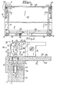
- Figure 1 is a plan view of an exemplary card cage or cabinet 10 having parallel upper and lower front frame members 12 and parallel upper and lower rear frame members 14. These members are supported by a pair of parallel end pieces (not shown) and are oriented perpendicular to the plane of an inserted PCB. Suspended between the upper front and rear frame members and the lower front and rear frame members are a number of card guides 16 which form channels which receive a PCB when it is inserted into the cabinet and direct its progress through the interior of the cabinet to one or more card sockets 18 located at the rear end thereof. These sockets are positioned between the upper and lower rear frame members, as shown in Figure 1.
- PCB 30 has along the length of its front edge, face plate 38 which is mounted perpendicular to the plane of board 30. Also as shown at "A" of Figure 1, there is attached to the outer surface 39 of face plate 38 at least one of injector/ejector devices 40 of the present invention. As shown, device 40 is affixed to face plate 38 at an upper and lower edge of PCB 30 in alignment with slots 41 in front frame members 12.
- FIGs 2 and 3 are enlarged side and end views of portion "A" of Figure 1 showing the overall structure of injection/ejection device 40 and its installation.
- the device is attached both to face plate 38 and frame member 12 by anchor pin 42.
- anchor pin 42 is essentially flat and key shaped having at its innermost end, engagement means 44 and at outermost head end, 46, a pivot hole 51 said ends being connected by shank 48. As shown in Figure 5, this is more or less square in cross section. Rigidly attached to and passing through hole 51 is pivot pin 52.
- anchor pin 42 When anchor pin 42 is operationally positioned it is in an aspect which is parallel to plane of PCB 30 so that pivot pin 52 will be parallel to frame members 12 and 14 and perpendicular to the plane of PCB 30.
- Bracket 54 Slidably fitted alongside of anchor pin 42 and mounted onto pivot pin 52 is at least one, preferably a pair, of brackets 54, with at least a portion of the innermost side 56 thereof engaging and firmly bearing against outer side 39 of face plate 38.
- Bracket 54 further comprises an extension 60 which includes a lower enlarged portion 61 and which, as shown in Figure 5, is configured to encase a lower portion of shank 48, said extension being shaped so that the encased combination will just barely pass through receiving hole 62 in face plate 38.
- receiving hole 62 is more or less rectangular in shape but with rounded ends and with the major axis being rotated approximately 45° relative to the horizontal and vertical axes of face plate 38.
- bracket 54 Located within bracket 54, as shown best in Figure 6, is right angled aperture 66 said aperture having a left portion 68 which is parallel to and aligned with the central axis of anchor pin 42 through which pivot pin 52 fits. Left portion 68 has a sufficient width for brackets 54 to slide freely up and down alongside of shank 48 relative to pivot pin 52, upon the application of a suitably directed linear force. Aperture 66 further contains a second or right portion 70 which is at right angles to left portion 68 and which further has an upper bearing surface 72.
- lever arm 76 Fitted outside of bracket 54 and anchor pin 42 is lever arm 76, which has a bifurcated construction 78 at one end comprising a pair of arms 81 rotatably connected to the ends of pivot pin 52, said rotation being facilitated by arcuate surface 80 so shaped that the distance between the part of said surface engaged with the side 56 of the plate 38 and the axis of the pivot pin 52 is progressively reduced as the lever arm 76 is rotated anti-clockwise, as seen in Figures 2 and 6.
- Arms 81 are configured to loosely fit outside of brackets 54 and anchor pin 42.
- spur 82 Located on the inner side of at least one of arms 81 is spur 82 which fits into the open interior of right portion 70 of aperture 66.
- spur 82 is configured so that upon a first, or counter clockwise rotation of lever arm 76 around pivot pin 52,'upper spur surface 84 will make an eccentric rolling contact with upper bearing surface 72 so as to exert a linear outwardly directed force thereon.
- the means by which the device of the present invention causes said pin insertion is as follows. After the device of the present invention is attached to face plate 38 as described hereinabove, the combined structure is inserted into and then pushed through cabinet 10 along guides 16 until plug 32 has made initial contact with socket 18 so that each of plug pins 24 has been partially inserted into its corresponding socket hole 36. At the same time innermost end 88 of anchor pin 42 contacts mounting hole 92. Lever arm 76 is then rotated to stand upright and perpendicular to the plane of face plate 38 to create a linear outwardly directed force. This will cause bracket 54 and clamped face plate 38 of PCB 30 to slide outwardly along the length of anchor pin 42.
- bracket 54 has moved to a point where pivot pin 52 is close to or in contact with the innermost end of left aperture 66.
- Device 40 is then rotated around the axis of anchor pin 42 until the plane of the device is more or less perpendicular to the lengthwise axis of face plate 38 and parallel to upper crossbar 12. As shown in Figure 7, such rotation enables the quick and easy attachment of device 40 to crossbar 12 by aligning the flat surfaces of anchor pin 42 at inner end 88 with opposed slots 90 in one of mounting holes 92 so as to slip easily thereinto.
- a plurality of holes 92 will be spread along the length of frame insert 94, in a spaced relationship with the planes of guides 16.
- Final injection of the board and seating of pins 34 comprises reverse rotation of still upstanding lever arm 76 around pivot 52 to the position shown in Figure 2 to generate the aforesaid linear inwardly directed force.
- brackets 54 and clamped face plate 38 of PCB 30 are caused to slide inwardly back along the shank 48 by the eccentric camlike action of arcuate surface 80 as it rotationally bears upon outer side 39 thus exerting said linear mating inward force upon plug 32.
- bracket extension 60 also closely fits into and is retained within the confines of slot 41 so that after said clockwise lever arm rotation, further rotation of device 40 is prevented and accidental disengagement of device 40 from mounting hole 92 is avoided.
- Removal of the board is accomplished merely by reversing the aforesaid actions i.e. reverse rotating lever arm 76 to generate the aforesaid outwardly directed force so that the pins of plug 32 are demated from socket 18 and then rotating device 40 90° to reciprocally disengage anchor pin 42 from mounting hole 92.
- the circuit board is loose enough for it to be easily pulled back along guides 16 and removed from cage 10.
Landscapes
- Engineering & Computer Science (AREA)
- Microelectronics & Electronic Packaging (AREA)
- Accommodation For Nursing Or Treatment Tables (AREA)
- Coupling Device And Connection With Printed Circuit (AREA)
- Mounting Of Printed Circuit Boards And The Like (AREA)
Applications Claiming Priority (2)
| Application Number | Priority Date | Filing Date | Title |
|---|---|---|---|
| US06/809,473 US4638405A (en) | 1985-12-16 | 1985-12-16 | Injector/ejector device for circuit board |
| US809473 | 1985-12-16 |
Publications (2)
| Publication Number | Publication Date |
|---|---|
| EP0228235A2 true EP0228235A2 (de) | 1987-07-08 |
| EP0228235A3 EP0228235A3 (de) | 1988-02-10 |
Family
ID=25201430
Family Applications (1)
| Application Number | Title | Priority Date | Filing Date |
|---|---|---|---|
| EP86309794A Withdrawn EP0228235A3 (de) | 1985-12-16 | 1986-12-16 | Vorrichtung zum Einschieben und zum Herausziehen eines zu einem rahmenartigen Chassis gehörenden Geräts |
Country Status (2)
| Country | Link |
|---|---|
| US (1) | US4638405A (de) |
| EP (1) | EP0228235A3 (de) |
Cited By (2)
| Publication number | Priority date | Publication date | Assignee | Title |
|---|---|---|---|---|
| GB2296995A (en) * | 1995-01-23 | 1996-07-17 | Schroff Gmbh | Pull-out apparatus for plug-in units |
| US5587888A (en) * | 1995-01-23 | 1996-12-24 | Schroff Gmbh | Extracting device for plug-in modules |
Families Citing this family (20)
| Publication number | Priority date | Publication date | Assignee | Title |
|---|---|---|---|---|
| US4780792A (en) * | 1986-08-15 | 1988-10-25 | Honeywell Inc. | Sliding circuit card ejection apparatus and method |
| US4778394A (en) * | 1986-12-19 | 1988-10-18 | International Business Machines Corporation | Pluggable electronic cartridge extractor |
| GB2205689A (en) * | 1987-06-09 | 1988-12-14 | Philips Electronic Associated | Printed circuit board handle |
| US4840569A (en) * | 1988-06-27 | 1989-06-20 | Itt Corporation | High density rotary connector |
| US4867695A (en) * | 1988-12-12 | 1989-09-19 | Ncr Corporation | Circuit board separation device |
| US4929185A (en) * | 1989-04-03 | 1990-05-29 | Nrc Corporation | Printed circuit board assembly |
| DE9012143U1 (de) * | 1990-08-23 | 1990-10-25 | Knürr-Mechanik für die Elektronik AG, 8000 München | Steck- und Ziehhilfe |
| US5268821A (en) * | 1991-03-06 | 1993-12-07 | Tandem Computers Incorporated | Shared pc board ejector/injector tool |
| US5222897A (en) * | 1992-04-01 | 1993-06-29 | Emc Corporation | Circuit board inserter/ejector system |
| US5317480A (en) * | 1992-08-21 | 1994-05-31 | At&T Bell Laboratories | Circuit pack interconnection |
| US5429523A (en) * | 1993-05-11 | 1995-07-04 | Robinson Nugent, Inc. | Electrical connector socket with daughtercard ejector |
| US5302133A (en) * | 1993-05-11 | 1994-04-12 | Robinson Nugent, Inc. | Electrical connector socket with daughtercard ejector |
| US5364282A (en) * | 1993-08-16 | 1994-11-15 | Robinson Nugent, Inc. | Electrical connector socket with daughtercard ejector |
| US5801926A (en) * | 1997-04-08 | 1998-09-01 | Cutsforth; Robert S. | Circuit card ejector device |
| US7014118B1 (en) | 1997-10-10 | 2006-03-21 | Robinson Nugent, Inc | Module header apparatus |
| DE19823648C1 (de) * | 1998-05-27 | 1999-11-04 | Metz Albert Ria Electronic | Anschlußklemme |
| US5978233A (en) * | 1998-06-18 | 1999-11-02 | Roscoe; Brett D. | Swell-latch printed circuit board latching and ejecting mechanism |
| US6146176A (en) * | 1999-08-27 | 2000-11-14 | Intel Corporation | Connector for connecting first and second parts, especially printed circuit boards |
| US8369094B2 (en) | 2010-05-19 | 2013-02-05 | Fujitsu Limited | Unibody latch for plug-in units |
| TWM603661U (zh) * | 2020-07-23 | 2020-11-01 | 瑞傳科技股份有限公司 | 電子裝置機板省力抽拔結構 |
Family Cites Families (7)
| Publication number | Priority date | Publication date | Assignee | Title |
|---|---|---|---|---|
| DE1553592A1 (de) * | 1966-04-21 | 1969-09-04 | Siemens Ag | Befestigungsvorrichtung fuer Schaltungsbausteine in einem Einschubtraeger |
| US3575482A (en) * | 1969-06-05 | 1971-04-20 | Rex Chainbelt Inc | Self-adjusting positive locking chassis latch |
| US4301494A (en) * | 1979-09-28 | 1981-11-17 | Wescom, Inc. | Printed circuit board faceplate assembly |
| US4345809A (en) * | 1980-06-09 | 1982-08-24 | Sugden Mary L | Circuit board ejector and guide |
| US4414605A (en) * | 1981-06-29 | 1983-11-08 | The United States Of America As Represented By The Secretary Of The Navy | Positive locking mechanism |
| US4497528A (en) * | 1982-08-06 | 1985-02-05 | Sperry Corporation | Avionics chassis insertion/extraction mechanism |
| DE3310136A1 (de) * | 1983-03-21 | 1984-09-27 | Siemens AG, 1000 Berlin und 8000 München | Codierbarer steckverbinder |
-
1985
- 1985-12-16 US US06/809,473 patent/US4638405A/en not_active Expired - Fee Related
-
1986
- 1986-12-16 EP EP86309794A patent/EP0228235A3/de not_active Withdrawn
Cited By (3)
| Publication number | Priority date | Publication date | Assignee | Title |
|---|---|---|---|---|
| GB2296995A (en) * | 1995-01-23 | 1996-07-17 | Schroff Gmbh | Pull-out apparatus for plug-in units |
| GB2296995B (en) * | 1995-01-23 | 1996-12-11 | Schroff Gmbh | Pull-out apparatus for plug-in units |
| US5587888A (en) * | 1995-01-23 | 1996-12-24 | Schroff Gmbh | Extracting device for plug-in modules |
Also Published As
| Publication number | Publication date |
|---|---|
| EP0228235A3 (de) | 1988-02-10 |
| US4638405A (en) | 1987-01-20 |
Similar Documents
| Publication | Publication Date | Title |
|---|---|---|
| EP0228235A2 (de) | Vorrichtung zum Einschieben und zum Herausziehen eines zu einem rahmenartigen Chassis gehörenden Geräts | |
| US4857017A (en) | Support device for wires in multi-contact connectors | |
| CN111600155B (zh) | 连接器组件 | |
| US4990097A (en) | Electrical connector with module extraction apparatus | |
| US5137462A (en) | Adapter for stacking connector assembly | |
| US4445740A (en) | Circuit board assembly | |
| US5364282A (en) | Electrical connector socket with daughtercard ejector | |
| CA1270056A (en) | Card cassette ejector apparatus | |
| US7462067B1 (en) | Cable-to-cable panel mount power connector | |
| EP0676836B1 (de) | Elektrischer Verbinder mit Saugplattform zur Erleichterung des Aufnehmens | |
| US6071143A (en) | Cabinet for insertion of circuit boards in tight spaces | |
| US4550362A (en) | Board positioning arrangement | |
| US5046237A (en) | Extractor tool | |
| US8348693B2 (en) | Electrical connector interface with latch operated by threaded drive shaft | |
| US4842543A (en) | Contact protection system for electrical connectors | |
| US5244403A (en) | Electronic component socket with external latch | |
| JPH04214698A (ja) | 補助回路カード用支持部材 | |
| EP1978606A2 (de) | An eine Montageplatte zu befestigen Verbinder mit Schiebverrastung | |
| EP1863136A2 (de) | Elektrischer Verbinder mit versetzten Kontakten | |
| IE902729A1 (en) | Contact terminal in a circuit panel socket | |
| US4971571A (en) | Self-locking pin field connector | |
| US4936790A (en) | Low insertion force connector | |
| US7004773B1 (en) | Electrical connector socket with latch mechanism | |
| US5801926A (en) | Circuit card ejector device | |
| US5395261A (en) | Serviceable data terminal structure |
Legal Events
| Date | Code | Title | Description |
|---|---|---|---|
| PUAI | Public reference made under article 153(3) epc to a published international application that has entered the european phase |
Free format text: ORIGINAL CODE: 0009012 |
|
| AK | Designated contracting states |
Kind code of ref document: A2 Designated state(s): DE FR GB |
|
| 17P | Request for examination filed |
Effective date: 19870710 |
|
| PUAL | Search report despatched |
Free format text: ORIGINAL CODE: 0009013 |
|
| AK | Designated contracting states |
Kind code of ref document: A3 Designated state(s): DE FR GB |
|
| 17Q | First examination report despatched |
Effective date: 19891013 |
|
| STAA | Information on the status of an ep patent application or granted ep patent |
Free format text: STATUS: THE APPLICATION IS DEEMED TO BE WITHDRAWN |
|
| 18D | Application deemed to be withdrawn |
Effective date: 19900224 |
|
| RIN1 | Information on inventor provided before grant (corrected) |
Inventor name: SMITH, KENNETH R. |