EP0228335A1 - Lingotière de coulée continue à tête chaude - Google Patents
Lingotière de coulée continue à tête chaude Download PDFInfo
- Publication number
- EP0228335A1 EP0228335A1 EP86440098A EP86440098A EP0228335A1 EP 0228335 A1 EP0228335 A1 EP 0228335A1 EP 86440098 A EP86440098 A EP 86440098A EP 86440098 A EP86440098 A EP 86440098A EP 0228335 A1 EP0228335 A1 EP 0228335A1
- Authority
- EP
- European Patent Office
- Prior art keywords
- ingot mold
- insert
- refractory material
- mold according
- thermal conductivity
- Prior art date
- Legal status (The legal status is an assumption and is not a legal conclusion. Google has not performed a legal analysis and makes no representation as to the accuracy of the status listed.)
- Granted
Links
Images


Classifications
-
- B—PERFORMING OPERATIONS; TRANSPORTING
- B22—CASTING; POWDER METALLURGY
- B22D—CASTING OF METALS; CASTING OF OTHER SUBSTANCES BY THE SAME PROCESSES OR DEVICES
- B22D11/00—Continuous casting of metals, i.e. casting in indefinite lengths
- B22D11/04—Continuous casting of metals, i.e. casting in indefinite lengths into open-ended moulds
- B22D11/059—Mould materials or platings
Definitions
- the invention relates to a vertical or substantially vertical ingot mold for the continuous casting of molten metals such as steel. More particularly, the invention relates to an ingot mold made of copper or copper alloy, with a hot head, that is to say in which the heat exchanges, at the meniscus, between the cast metal and the ingot mold are slowed down so as to to reduce the oscillation wrinkles on the cast product.
- this metal insert the average thickness of which can be a few millimeters (the thickness can be uniform, or even decrease from top to bottom of the insert), is done using an expensive technique (generally plating by explosion) due to the need to obtain perfect contact between the metal insert and the wall of the mold.
- This necessity results in particular from the fact that any non-zero contact thermal resistance introduces a predetermined and non-reproducible datum into the overall thermal resistance of the mold.
- these ingot molds often include a surface wear coating of nickel intended to avoid the formation of star cracks in the cast product: the addition of a thermal contact resistance risks bringing the nickel to a close temperature. of its limit around 600 ° C (temperature metal thickness near the wall: around 1540 ° C).
- the object of the invention is to propose a new type of insert for an ingot mold with a hot head, which does not have the above-mentioned drawbacks.
- the insert about 10 to 20 cm long, is constituted by a thin deposit of a refractory material with low thermal conductivity having good resistance to thermal shock, and whose thickness, taken between approximately 200 and 500 ⁇ m, is chosen so that, at the contact temperature of the metal with said deposited material, said metal in the course of solidification has a solid fraction of between 25 and 35% by weight approximately.
- the inventors have in fact found that if the solid fraction at the surface of the cast metal is greater than about 35%, a thick and rigid horn is obtained by cooling in the region of the meniscus near the wall of the mold. more deform, resulting in the formation of oscillation wrinkles.
- the refractory materials chosen resist temperatures of around 1800 ° C. Their thermal conductivity is preferably less than 10 W.m ⁇ 1K ⁇ 1, to be compared to conductivities of the order of 50, 100 and 300 W.m ⁇ 1K respectivement1 respectively for inserts in stainless steel, nickel and copper-silver alloy.
- the small thicknesses envisaged are advantageously between 2 and 5/10 th of a mm, to be compared to a few millimeters of thickness of the metal inserts.
- the refractory materials are in particular alumina (melting temperature: 2040 ° C; thermal conductivity ranging between 2 Wm ⁇ 1K ⁇ 1 and higher values depending on the treatment undergone), zirconia (melting temperature: 2700 ° C; thermal conductivity: 1 Wm ⁇ 1K ⁇ 1), boron nitride, or, so preferred, chromium carbide (melting temperature: 1800 °; thermal conductivity: 7.5 Wm ⁇ 1K ⁇ 1).
- the deposition of the material is obtained by spraying in a hot powder manner, for example by means of a plasma torch or preferably a detonation gun (according to the technique marketed by the company "Union Carbon Corporation"), followed polishing.
- a plasma torch or preferably a detonation gun according to the technique marketed by the company "Union Carbon Corporation"
- This technique provides excellent adhesion between the support and the filler material, and a homogeneous coating free of roughness.
- the deposit is made in a recess in the wall of the ingot mold, of depth equal to the thickness of the deposit, made either in the copper of the wall, or in the surface coating of nickel or chromium if one is provided. .
- the copper wall 1 has a recess 2 of 3/10 th mm in thickness and about fifteen centimeters in height covering the region of the meniscus taking account of the oscillations on the one hand and possible variations in average level.
- the recess 2 is filled with a deposit 3 of Cr3C2 obtained by projection with detonation cannon, followed by polishing.
- the recess 2 ⁇ is made from the chrome coating 4, 0.3 mm thick, covering the wall 1 ⁇ of the mold.
- the material 3 ⁇ is flush with the internal surface of the mold.
- the graph in FIG. 3 makes it possible to compare the values of the local densities of heat flow ⁇ c extracted by the ingot mold equipped with an insert according to the invention, made of chromium carbide (curve B), with the values obtained using a conventional ingot mold. without insert (curve A).
- the straight line C in broken lines located at d ⁇ 70 mm corresponds to the lower limit of the insert, which, in this particular case, and for an insert of approximately 150 mm high, indicates that the meniscus is substantially mid-height of said insert.
- the two curves A and B correspond to the continuous casting of slabs with an extraction speed of 1.3 m / min.
- the inventors were able to observe, by studying a mathematical model established for cooling in an ingot mold without insert, that the surface temperature of the steel in contact with the ingot mold is close to the solidus of the steel grade (1493 ° C), which indicates a significant solidification of the meniscus horn.
- the inventors found that it was necessary to divide by four the heat extraction provided by the copper walls in the vicinity of the meniscus.
- the density of thermal flux extracted by the ingot mold is substantially divided by a factor 4.
- the density of flux extracted at the meniscus is around 2 MW / m2 (curve A), and the use of a thin chromium carbide insert brings this value to around 500 kW / m2.
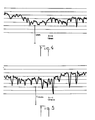
- Figures 4 and 5 compare the longitudinal profiles of the surface of a low carbon steel slab cast at the speed of 1.3 m / min with an oscillation frequency of 117 strokes per minute.
- Figure 4 corresponds to a profile obtained by solidification against the wall of an ingot mold equipped with an insert according to the invention
- Figure 5 corresponds to an equivalent profile obtained with a conventional ingot mold without insert.
- the invention is not limited to the embodiments and to the applications described above by way of example.
- the dimensions of the insert can be adapted to the molds and cast products.
- the casting parameters extraction speed, frequency of oscillations
- the mold according to the invention can be used both for continuous casting of slabs and other products (blooms).
Landscapes
- Engineering & Computer Science (AREA)
- Mechanical Engineering (AREA)
- Continuous Casting (AREA)
- Coating By Spraying Or Casting (AREA)
- Means For Warming Up And Starting Carburetors (AREA)
- Materials For Medical Uses (AREA)
- Ceramic Products (AREA)
- Prostheses (AREA)
- Confectionery (AREA)
Abstract
Description
- L'invention concerne une lingotière verticale ou sensiblement verticale pour la coulée continue des métaux en fusion tel que l'acier. Plus particulièrement, l'invention concerne une lingotière en cuivre ou alliage de cuivre, à tête chaude, c'est-à-dire dans laquelle les échanges thermiques, au niveau du ménisque, entre le métal coulé et la lingotière sont ralentis de manière à atténuer les rides d'oscillation sur le produit coulé.
- On connaît, par exemple par les documents FR-A-2 528 738 et FR-A-2 540 409, une telle lingotière, dont les parois énergétiquement refroidies par circulation d'un liquide de refroidissement, comportent à leur partie supérieure un insert ;métallique d'acier inoxydable, dont la conductivité thermique est inférieure à celle du métal constituant les parois de la lingotière. De la sorte, le métal est moins refroidi au voisinage du ménisque, ce qui permet de diminuer la profondeur des rides d'oscillation et la longueur de la corne solidifiée qui accompagne leur formation. On sait que de telles rides constituent des points sensibles où naissent préférentiellement des criques de surface préjudiciables à la qualité du produit fini.
- La mise en place de cet insert métallique, dont l'épaisseur moyenne peut être de quelques millimètres (l'épaisseur peut être uniforme, ou bien décroître du haut en bas de l'insert), se fait selon une technique coûteuse (en général placage par explosion) en raison de la nécessité d'obtenir un contact parfait entre l'insert métallique et la paroi de la lingotière. Cette nécessité résulte notamment du fait que toute résistance thermique de contact non nulle introduit une donnée prédéterminée et non reproductible dans la résistance thermique globale de la lingotière. D'autre part, ces lingotières comportent souvent un revêtement superficiel d'usure en nickel destiné à éviter la formation de criques en étoile dans le produit coulé : l'addition d'une résistance thermique de contact risque de conduire le nickel à une température proche de sa limite autour de 600°C (tempéra ture du métal au voisinage de la paroi : environ 1540°C).
- Le but de l'invention est de proposer un nouveau type d'insert pour lingotière à tête chaude, qui ne présente pas les inconvénients précités.
- Selon l'invention, l'insert, de 10 à 20 cm de long environ, est constitué par un mince dépôt d'un matériau réfractaire à faible conductivité thermique ayant une bonne tenue aux chocs thermiques, et dont l'épaisseur, prise entre environ 200 et 500µm, est choisie de manière que, à la température de contact du métal avec ledit matériau déposé, ledit métal en cours de solidification présente une fraction solide comprise entre 25 et 35 % environ en poids.
- Les inventeurs ont en effet constaté que si la fraction solide à la surface du métal coulé est supérieure à environ 35 %, on obtient, par refroidissement dans la zone du ménisque proche de la paroi de la lingotière, une corne épaisse et rigide qui ne peut plus se déformer, ce qui entraîne la formation des rides d'oscillation.
- Inversement, si la fraction solide est faible, le ménisque n'a plus de consistance ni rigidité; mais maintenir une fraction liquide inférieure à 25 % revient à inhiber une part importante du refroidissement en lingotière. Dans le domaine considéré, les matériaux réfractaires choisis résistent à des températures d'environ 1800°C. Leur conductivité thermique est de préférence inférieure à 10 W.m ⁻¹K⁻¹, à comparer à des conductivités de l'ordre de 50, 100 et 300 W.m⁻¹K⁻¹ respectivement pour des inserts en inox, nickel et alliage cuivre-argent.
- Les faibles épaisseurs envisagées sont avantageusement comprises entre 2 et 5/10e de mm, à comparer aux quelques millimètres d'épaisseur des inserts métalliques.
- Les matériaux réfractaires sont notamment l'alumine (température de fusion : 2040°C ; conducitivité thermique s'échelonnant entre 2 W.m⁻¹K⁻¹ et des valeurs supérieures selon le traitement subi), la zircone (température de fusion : 2700°C ; conductivité thermique : 1 W.m⁻¹K⁻¹), le nitrure de bore, ou, de manière préférée, le carbure de chrome (température de fusion : 1800° ; conductivité thermique : 7,5 W.m⁻¹K⁻¹).
- Le dépôt du matériau s'obtient par projection de manière pulvérulente à chaud, par exemple au moyen d'une torche à plasma ou de préférence d'un canon à détonation (selon la technique commercialisée par la société "Union Carbon Corporation"), suivi d'un polissage. Cette technique permet d'obtenir un accrochage excellent entre le support et le matériau d'apport, et un revêtement homogène exempt d'aspérité.
- Le dépôt est pratiqué dans un évidement de la paroi de la lingotière, de profondeur égale à l'épaisseur de dépôt, pratiqué soit dans le cuivre de la paroi, soit dans le revêtement superficiel de nickel ou de chrome s'il en est prévu un.
- D'autres caractéristiques et avantages apparaîtront dans la description qui va être faite d'un mode particulier de réalisation de l'invention. On se reportera aux dessins annexés dans lesquels :
- - la figure 1 représente une coupe partielle de la paroi d'une lingotière conforme à l'invention,
- - la figure 2 est une vue similaire lorsque la lingotière est pourvue d'un revêtement superficiel,
- - la figure 3 est un graphique montrant la variation du flux surfacique de chaleur dissipée par la lingotière en fonction de la distance par rapport à la surface du ménisque (ordonnée 0),
- - figure 4 est une représentation du profil des rides d'oscillations sur des brames de coulée continue dans une lingotière selon l'invention,
- - figure 5 est une représentation similaire avec une lingotière sans insert.
- Sur la figure 1, la paroi 1 en cuivre comporte un évidement 2 de 3/10e mm d'épaisseur et d'une quinzaine de centimètres de hauteur couvrant la région du ménisque compte tenu des oscillations d'une part et des éventuelles variations de niveau moyen. L'évidement 2 est comblé par un dépôt 3 de Cr₃C₂ obtenu par projection au canon à détonation, suivi d'un polissage.
- Sur la figure 2, l'évidement 2ʹ est pratiqué à partir du revêtement de chrome 4, de 0,3 mm d'épaisseur, couvrant la paroi 1ʹ de la lingotière. Le matériau 3ʹ affleure la surface interne de la lingotière.
- Le graphique de la figure 3 permet de comparer les valeurs des densités locales de flux thermique Φc extrait par la lingotière équipée d'un insert selon l'invention, en carbure de chrome (courbe B), aux valeurs obtenues en utilisant une lingotière conventionnelle sans insert (courbe A). La droite C en traits interrompus située à d ≃ 70 mm, correspond à la limite inférieure de l'insert, ce qui, dans ce cas particulier, et pour un insert de 150 mm de haut environ, indique que le ménisque se trouve sensiblement à mi- hauteur dudit insert. Les deux courbes A et B correspondent à la couléecontinue de brames avec une vitesse d'extraction de 1,3 m/min.
- Dans les conditions d'échange thermique retenues pour cet exemple, les inventeurs ont pu constater,par l'étude d'un modèle mathématique établi pour un refroidissement en lingotière sans insert, que la température de surface de l'acier au contact avec la lingotière est proche du solidus de la nuance d'acier (1493°C), ce qui indique une solidification importante de la corne du ménisque. Pour ramener la fraction solidifiée au contact avec la lingotière à environ 30 %, les inventeurs ont trouvé qu'il fallait diviser par quatrel'extraction calorifique assurée par les parois de cuivre au voisinage du ménisque.
- On remarque sur la figure 3 que, conformément au but recherché, dans la zone de l'insert la densité de flux thermique extrait par la lingotière est sensiblement divisé par un facteur 4. En effet dans une lingotière classique, la densité de flux extrait au voisinage du ménisque est de l'ordre de 2 MW/m² (courbe A), et l'utilisation d'un insert mince en carbure de chrome ramène cette valeur au voisinage de 500 kW/m².
- De plus, dès la sortie de l'insert (ligne en traits interrompus), l'extraction calorifique mesurée localement est proche des valeurs obtenues sur une lingotière conventionnelle, ce qui permet de constater que le refroidissement global en lingotière en dessous de l'insert est peu perturbé par la présence de celui-ci.
- Les figures 4 et 5 permettent de comparer les profils longitudinaux de la surface d'une brame d'acier à bas carbone coulée à la vitesse de 1,3 m/min avec une fréquence d'oscillation de 117 coups par minute. La figure 4 correspond à un profil obtenu par solidification contre la paroi d'une lingotière équipée d'un insert selon l'invention, et la figure 5 correspond à un profil équivalent obtenu avec une lingotière conventionnelle sans insert.
- Il apparaît clairement que l'utilisation d'un insert diminue notablement la profondeur des rides d'oscillation à la surface du produit, et améliore leur régularité. On a observé lors d'essais réalisés dans des conditions de coulée analogues, une diminution systématique de 25 à 40 % de la profondeur des rides d'oscillation.
- D'autres essais réalisés avec des brames d'acier moyen carbone (c'est-à-dire à teneur en carbone voisine de 0,1 %) coulées à une vitesse de 0,8 m/min avec une fréquence d'oscillation de 80 coups par minute, ont permis de mettre en évidence la différence de structure de solidification de la première peau d'une brame selon qu'elle est solidifiée dans une lingotière sans insert conforme à l'invention.
- L'observation d'échantillons prélevés longitudinalement dans lesdites brames et attaqués par le réactif de Bechet-Beaugeard, révèle que, dans le cas de la lingotière conventionnelle sans insert, les rides sont profondes et se prolongent par une hétérogénéité de solidification résultant de la formation de la corne solidifiée au niveau du ménisque. La profondeur de la corne solidifiée est lors d'environ 1,7 mm. Dans le cas de la lingotière avec insert selon l'invention, les rides apparaîssent beaucoup moins marquées et la profondeur de pénétration de la corne solidifiée n'est que de 0,9 mm soit environ la moitié seulement de la valeur observée en l'absence d'insert.
- Bien entendu, l'invention n'est pas limitée aux modes de réalisation et aux applications décrites ci-dessus à titre d'exemple. En particulier les dimensions de l'insert peuvent être adaptées aux lingotières et produits coulés. Les paramètres de coulée (vitesse d'extraction, fréquence des oscillations) peuvent être adaptés et la lingotière selon l'invention peut être utilisée aussi bien en coulée continue de brames que d'autres produits (blooms).
Claims (6)
Priority Applications (1)
| Application Number | Priority Date | Filing Date | Title |
|---|---|---|---|
| AT86440098T ATE62159T1 (de) | 1985-11-15 | 1986-11-06 | Stranggiesskokille mit warmhaube. |
Applications Claiming Priority (2)
| Application Number | Priority Date | Filing Date | Title |
|---|---|---|---|
| FR8516954A FR2590188B1 (fr) | 1985-11-15 | 1985-11-15 | Lingotiere de coulee continue a tete chaude |
| FR8516954 | 1985-11-15 |
Publications (2)
| Publication Number | Publication Date |
|---|---|
| EP0228335A1 true EP0228335A1 (fr) | 1987-07-08 |
| EP0228335B1 EP0228335B1 (fr) | 1991-04-03 |
Family
ID=9324879
Family Applications (1)
| Application Number | Title | Priority Date | Filing Date |
|---|---|---|---|
| EP86440098A Expired - Lifetime EP0228335B1 (fr) | 1985-11-15 | 1986-11-06 | Lingotière de coulée continue à tête chaude |
Country Status (7)
| Country | Link |
|---|---|
| EP (1) | EP0228335B1 (fr) |
| JP (1) | JPS62118948A (fr) |
| AT (1) | ATE62159T1 (fr) |
| CA (1) | CA1310170C (fr) |
| DE (1) | DE3678549D1 (fr) |
| ES (1) | ES2021609B3 (fr) |
| FR (1) | FR2590188B1 (fr) |
Cited By (4)
| Publication number | Priority date | Publication date | Assignee | Title |
|---|---|---|---|---|
| WO1992019399A1 (fr) * | 1991-04-27 | 1992-11-12 | Foseco International Limited | Piece rapportee destinee a des recipients ou a des tuyaux contenant du metal en fusion |
| GB2318314A (en) * | 1996-10-15 | 1998-04-22 | Davy Distington Ltd | Continuous casting mould with a coating of varying thickness |
| EP1642659A3 (fr) * | 2004-10-04 | 2006-05-24 | Outokumpu Copper Products Oy | Procédé et dispositif pour la coulée continue d'alliages de cuivre |
| DE10256751B4 (de) | 2002-10-17 | 2019-09-12 | Sms Group Gmbh | Stranggießkokille zum Gießen von Strängen aus Metallen, insbesondere aus Stahlwerkstoffen |
Families Citing this family (1)
| Publication number | Priority date | Publication date | Assignee | Title |
|---|---|---|---|---|
| CN107148322B (zh) * | 2014-10-28 | 2019-09-03 | 杰富意钢铁株式会社 | 连续铸造用铸模及钢的连续铸造方法 |
Citations (3)
| Publication number | Priority date | Publication date | Assignee | Title |
|---|---|---|---|---|
| FR1517577A (fr) * | 1967-04-05 | 1968-03-15 | Ducommun Inc | Lingotière perfectionnée |
| FR2041714A1 (en) * | 1969-05-09 | 1971-02-05 | Inst Chernoi Metallurgii | Ingot mould for continuous steel casting |
| GB2157600A (en) * | 1984-04-21 | 1985-10-30 | Kabel Metallwerke Ghh | Producing continuous-casting moulds |
Family Cites Families (4)
| Publication number | Priority date | Publication date | Assignee | Title |
|---|---|---|---|---|
| JPS5973152A (ja) * | 1982-10-21 | 1984-04-25 | Mishima Kosan Co Ltd | 連続鋳造用鋳型及びその製造方法 |
| JPS5973153A (ja) * | 1982-10-21 | 1984-04-25 | Mishima Kosan Co Ltd | 連続鋳造用鋳型及びその製造方法 |
| JPS59147751A (ja) * | 1983-02-09 | 1984-08-24 | Sumitomo Electric Ind Ltd | 連続鋳造圧延方法 |
| JPS59153550A (ja) * | 1983-02-23 | 1984-09-01 | Kawasaki Steel Corp | 連続鋳造用モ−ルド |
-
1985
- 1985-11-15 FR FR8516954A patent/FR2590188B1/fr not_active Expired
-
1986
- 1986-11-06 EP EP86440098A patent/EP0228335B1/fr not_active Expired - Lifetime
- 1986-11-06 AT AT86440098T patent/ATE62159T1/de not_active IP Right Cessation
- 1986-11-06 DE DE8686440098T patent/DE3678549D1/de not_active Expired - Lifetime
- 1986-11-06 ES ES86440098T patent/ES2021609B3/es not_active Expired - Lifetime
- 1986-11-14 CA CA000522961A patent/CA1310170C/fr not_active Expired - Lifetime
- 1986-11-15 JP JP61272750A patent/JPS62118948A/ja active Pending
Patent Citations (3)
| Publication number | Priority date | Publication date | Assignee | Title |
|---|---|---|---|---|
| FR1517577A (fr) * | 1967-04-05 | 1968-03-15 | Ducommun Inc | Lingotière perfectionnée |
| FR2041714A1 (en) * | 1969-05-09 | 1971-02-05 | Inst Chernoi Metallurgii | Ingot mould for continuous steel casting |
| GB2157600A (en) * | 1984-04-21 | 1985-10-30 | Kabel Metallwerke Ghh | Producing continuous-casting moulds |
Non-Patent Citations (4)
| Title |
|---|
| PATENTS ABSTRACTS OF JAPAN, vol. 8, no. 180 (M-318)[1617], 18 août 1984; & JP-A-59 073 152 (MISHIMA KOUSAN K.K.) 25-04-1984 * |
| PATENTS ABSTRACTS OF JAPAN, vol. 8, no. 180 (M-318)[1617], 18 août 1984; & JP-A-59 073 153 (MISHIMA KOUSAN K.K.) 25-04-1984 * |
| PATENTS ABSTRACTS OF JAPAN, vol. 8, no. 276 (M-346)[1713], 18 décembre 1984; & JP-A-59 147 751 (SUMITOMO DENKI KOGYO K.K.) 24-08-1984 * |
| PATENTS ABSTRACTS OF JAPAN, vol. 8, no. 284 (M-348)[1721], 26 décembre 1984; & JP-A-59 153 550 (KAWASAKI SEITETSU K.K.) 01-09-1984 * |
Cited By (5)
| Publication number | Priority date | Publication date | Assignee | Title |
|---|---|---|---|---|
| WO1992019399A1 (fr) * | 1991-04-27 | 1992-11-12 | Foseco International Limited | Piece rapportee destinee a des recipients ou a des tuyaux contenant du metal en fusion |
| GB2318314A (en) * | 1996-10-15 | 1998-04-22 | Davy Distington Ltd | Continuous casting mould with a coating of varying thickness |
| US6176298B1 (en) | 1996-10-15 | 2001-01-23 | Davy Distington Limited | Continuous casting mould |
| DE10256751B4 (de) | 2002-10-17 | 2019-09-12 | Sms Group Gmbh | Stranggießkokille zum Gießen von Strängen aus Metallen, insbesondere aus Stahlwerkstoffen |
| EP1642659A3 (fr) * | 2004-10-04 | 2006-05-24 | Outokumpu Copper Products Oy | Procédé et dispositif pour la coulée continue d'alliages de cuivre |
Also Published As
| Publication number | Publication date |
|---|---|
| ATE62159T1 (de) | 1991-04-15 |
| CA1310170C (fr) | 1992-11-17 |
| EP0228335B1 (fr) | 1991-04-03 |
| ES2021609B3 (es) | 1991-11-16 |
| JPS62118948A (ja) | 1987-05-30 |
| FR2590188A1 (fr) | 1987-05-22 |
| FR2590188B1 (fr) | 1988-07-29 |
| DE3678549D1 (de) | 1991-05-08 |
Similar Documents
| Publication | Publication Date | Title |
|---|---|---|
| AU756027B2 (en) | Making precision castings using thixotropic materials | |
| EP0519054B1 (fr) | Methode d'obtention de culasses moulees composites | |
| EP0228335B1 (fr) | Lingotière de coulée continue à tête chaude | |
| EP3645191B1 (fr) | Procede de fonderie avec coulee en moule chaud | |
| EP0989918B1 (fr) | Tete de lingotiere pour la coulee continue verticale en charge de produits metalliques a format allonge | |
| EP0743114B1 (fr) | Procédé de lubrification des parois d'une lingotière de coulée continue des métaux et lingotière pour sa mise en oeuvre | |
| EP0907439B1 (fr) | Lingotiere de coulee continue pour la coulee continue en charge verticale des metaux | |
| EP1097753B1 (fr) | Nouveau procédé de coulée centrifuge verticale pour cylindres de laminoirs permettant d'obtenir une liaison saine et sans porosités entre la couche externe en acier rapide et la fonte nodulaire du coeur. | |
| WO1997037791A1 (fr) | Lingotiere bi-materiau pour la coulee continue en charge verticale des metaux | |
| CZ289354B6 (cs) | Kokilová trubka pro kokilu pro kontinuální lití ocelí, zejména peritektických ocelí | |
| EP0891237B1 (fr) | Procede de coulee continue des metaux et lingotiere pour sa mise en oeuvre | |
| EP0993890B1 (fr) | Lingotiére tubulaire de coulée continue en charge des métaux | |
| CA2251007C (fr) | Procede de coulee continue des metaux et installation de coulee pour sa mise oeuvre | |
| BE1014604A3 (fr) | Dispositif ameliore pour fabriquer des produits plats par coulee continue en charge verticale d'un metal en fusion. | |
| EP0418182B1 (fr) | Dispositif de coulée continue de produits métalliques minces entre cylindres | |
| WO2000033991A1 (fr) | Dispositif pour la coulee continue en charge verticale d'un metal en fusion | |
| BE893777A (fr) | Perfectionnements aux procedes de coulee continue des metaux, et lingotiere pour la mise en oeuvre de ces procedes | |
| EP0452294A2 (fr) | Procédé et installation pour la coulée continue d'un métal | |
| BE454855A (fr) | ||
| FR2515995A1 (fr) | Moules de coulee continue d'acier |
Legal Events
| Date | Code | Title | Description |
|---|---|---|---|
| PUAI | Public reference made under article 153(3) epc to a published international application that has entered the european phase |
Free format text: ORIGINAL CODE: 0009012 |
|
| AK | Designated contracting states |
Kind code of ref document: A1 Designated state(s): AT BE DE ES GB IT LU NL SE |
|
| 17P | Request for examination filed |
Effective date: 19871203 |
|
| 17Q | First examination report despatched |
Effective date: 19890209 |
|
| GRAA | (expected) grant |
Free format text: ORIGINAL CODE: 0009210 |
|
| AK | Designated contracting states |
Kind code of ref document: B1 Designated state(s): AT BE DE ES GB IT LU NL SE |
|
| REF | Corresponds to: |
Ref document number: 62159 Country of ref document: AT Date of ref document: 19910415 Kind code of ref document: T |
|
| ITF | It: translation for a ep patent filed | ||
| REF | Corresponds to: |
Ref document number: 3678549 Country of ref document: DE Date of ref document: 19910508 |
|
| GBT | Gb: translation of ep patent filed (gb section 77(6)(a)/1977) | ||
| PLBE | No opposition filed within time limit |
Free format text: ORIGINAL CODE: 0009261 |
|
| STAA | Information on the status of an ep patent application or granted ep patent |
Free format text: STATUS: NO OPPOSITION FILED WITHIN TIME LIMIT |
|
| 26N | No opposition filed | ||
| EPTA | Lu: last paid annual fee | ||
| EAL | Se: european patent in force in sweden |
Ref document number: 86440098.1 |
|
| REG | Reference to a national code |
Ref country code: GB Ref legal event code: IF02 |
|
| PGFP | Annual fee paid to national office [announced via postgrant information from national office to epo] |
Ref country code: GB Payment date: 20031029 Year of fee payment: 18 |
|
| PGFP | Annual fee paid to national office [announced via postgrant information from national office to epo] |
Ref country code: NL Payment date: 20031030 Year of fee payment: 18 |
|
| PGFP | Annual fee paid to national office [announced via postgrant information from national office to epo] |
Ref country code: LU Payment date: 20031031 Year of fee payment: 18 |
|
| PGFP | Annual fee paid to national office [announced via postgrant information from national office to epo] |
Ref country code: SE Payment date: 20031103 Year of fee payment: 18 Ref country code: DE Payment date: 20031103 Year of fee payment: 18 |
|
| PGFP | Annual fee paid to national office [announced via postgrant information from national office to epo] |
Ref country code: AT Payment date: 20031105 Year of fee payment: 18 |
|
| PGFP | Annual fee paid to national office [announced via postgrant information from national office to epo] |
Ref country code: ES Payment date: 20031119 Year of fee payment: 18 |
|
| PGFP | Annual fee paid to national office [announced via postgrant information from national office to epo] |
Ref country code: BE Payment date: 20031209 Year of fee payment: 18 |
|
| PG25 | Lapsed in a contracting state [announced via postgrant information from national office to epo] |
Ref country code: LU Free format text: LAPSE BECAUSE OF NON-PAYMENT OF DUE FEES Effective date: 20041106 Ref country code: GB Free format text: LAPSE BECAUSE OF NON-PAYMENT OF DUE FEES Effective date: 20041106 Ref country code: AT Free format text: LAPSE BECAUSE OF NON-PAYMENT OF DUE FEES Effective date: 20041106 |
|
| PG25 | Lapsed in a contracting state [announced via postgrant information from national office to epo] |
Ref country code: SE Free format text: LAPSE BECAUSE OF NON-PAYMENT OF DUE FEES Effective date: 20041107 |
|
| PG25 | Lapsed in a contracting state [announced via postgrant information from national office to epo] |
Ref country code: ES Free format text: LAPSE BECAUSE OF NON-PAYMENT OF DUE FEES Effective date: 20041108 |
|
| PG25 | Lapsed in a contracting state [announced via postgrant information from national office to epo] |
Ref country code: BE Free format text: LAPSE BECAUSE OF NON-PAYMENT OF DUE FEES Effective date: 20041130 |
|
| BERE | Be: lapsed |
Owner name: INSTITUT DE RECHERCHES DE LA SIDERURGIE FRANCAISE Effective date: 20041130 |
|
| PG25 | Lapsed in a contracting state [announced via postgrant information from national office to epo] |
Ref country code: NL Free format text: LAPSE BECAUSE OF NON-PAYMENT OF DUE FEES Effective date: 20050601 Ref country code: DE Free format text: LAPSE BECAUSE OF NON-PAYMENT OF DUE FEES Effective date: 20050601 |
|
| GBPC | Gb: european patent ceased through non-payment of renewal fee |
Effective date: 20041106 |
|
| EUG | Se: european patent has lapsed | ||
| NLV4 | Nl: lapsed or anulled due to non-payment of the annual fee |
Effective date: 20050601 |
|
| PG25 | Lapsed in a contracting state [announced via postgrant information from national office to epo] |
Ref country code: IT Free format text: LAPSE BECAUSE OF NON-PAYMENT OF DUE FEES;WARNING: LAPSES OF ITALIAN PATENTS WITH EFFECTIVE DATE BEFORE 2007 MAY HAVE OCCURRED AT ANY TIME BEFORE 2007. THE CORRECT EFFECTIVE DATE MAY BE DIFFERENT FROM THE ONE RECORDED. Effective date: 20051106 |
|
| REG | Reference to a national code |
Ref country code: ES Ref legal event code: FD2A Effective date: 20041108 |
|
| BERE | Be: lapsed |
Owner name: INSTITUT DE RECHERCHES DE LA SIDERURGIE FRANCAISE Effective date: 20041130 |