EP0228466B1 - Dispositif de commande de l'ecoulement d'un fluide et appareil l'utilisant - Google Patents
Dispositif de commande de l'ecoulement d'un fluide et appareil l'utilisant Download PDFInfo
- Publication number
- EP0228466B1 EP0228466B1 EP86904697A EP86904697A EP0228466B1 EP 0228466 B1 EP0228466 B1 EP 0228466B1 EP 86904697 A EP86904697 A EP 86904697A EP 86904697 A EP86904697 A EP 86904697A EP 0228466 B1 EP0228466 B1 EP 0228466B1
- Authority
- EP
- European Patent Office
- Prior art keywords
- valve
- water
- liquid
- receptacle
- flow
- Prior art date
- Legal status (The legal status is an assumption and is not a legal conclusion. Google has not performed a legal analysis and makes no representation as to the accuracy of the status listed.)
- Expired - Lifetime
Links
- 239000007788 liquid Substances 0.000 claims abstract description 63
- XLYOFNOQVPJJNP-UHFFFAOYSA-N water Substances O XLYOFNOQVPJJNP-UHFFFAOYSA-N 0.000 claims abstract description 43
- 239000002250 absorbent Substances 0.000 claims abstract description 34
- -1 polyethylene Polymers 0.000 claims abstract description 27
- 239000004698 Polyethylene Substances 0.000 claims abstract description 14
- 229920000573 polyethylene Polymers 0.000 claims abstract description 14
- 229920005989 resin Polymers 0.000 claims description 51
- 239000011347 resin Substances 0.000 claims description 51
- 239000000203 mixture Substances 0.000 claims description 10
- 241000894006 Bacteria Species 0.000 claims description 9
- 229920000098 polyolefin Polymers 0.000 claims description 9
- 239000000945 filler Substances 0.000 claims description 8
- 230000002745 absorbent Effects 0.000 claims description 6
- 238000009736 wetting Methods 0.000 claims description 6
- 239000004743 Polypropylene Substances 0.000 claims description 4
- 239000000155 melt Substances 0.000 claims description 4
- 229920001155 polypropylene Polymers 0.000 claims description 4
- 241000589516 Pseudomonas Species 0.000 claims description 3
- 230000004044 response Effects 0.000 claims description 3
- 239000012260 resinous material Substances 0.000 claims description 2
- 230000000717 retained effect Effects 0.000 claims description 2
- 230000001580 bacterial effect Effects 0.000 claims 1
- 239000000463 material Substances 0.000 abstract description 45
- 239000002245 particle Substances 0.000 abstract description 14
- 210000001124 body fluid Anatomy 0.000 abstract description 11
- 239000010839 body fluid Substances 0.000 abstract description 11
- 239000012530 fluid Substances 0.000 description 15
- 229920002472 Starch Polymers 0.000 description 14
- 239000008107 starch Substances 0.000 description 14
- 235000019698 starch Nutrition 0.000 description 14
- 239000007789 gas Substances 0.000 description 13
- 238000001914 filtration Methods 0.000 description 8
- 229920000578 graft copolymer Polymers 0.000 description 7
- 238000000034 method Methods 0.000 description 7
- 229920000642 polymer Polymers 0.000 description 7
- 239000008280 blood Substances 0.000 description 6
- 210000004369 blood Anatomy 0.000 description 6
- 229920003023 plastic Polymers 0.000 description 6
- 239000004033 plastic Substances 0.000 description 6
- 241000894007 species Species 0.000 description 5
- 239000000126 substance Substances 0.000 description 5
- NLHHRLWOUZZQLW-UHFFFAOYSA-N Acrylonitrile Chemical compound C=CC#N NLHHRLWOUZZQLW-UHFFFAOYSA-N 0.000 description 4
- 239000000356 contaminant Substances 0.000 description 4
- 238000011109 contamination Methods 0.000 description 4
- 230000003301 hydrolyzing effect Effects 0.000 description 4
- 239000011148 porous material Substances 0.000 description 4
- KWYUFKZDYYNOTN-UHFFFAOYSA-M Potassium hydroxide Chemical compound [OH-].[K+] KWYUFKZDYYNOTN-UHFFFAOYSA-M 0.000 description 3
- 150000007942 carboxylates Chemical class 0.000 description 3
- 229920001577 copolymer Polymers 0.000 description 3
- 239000000835 fiber Substances 0.000 description 3
- 230000007062 hydrolysis Effects 0.000 description 3
- 238000006460 hydrolysis reaction Methods 0.000 description 3
- 238000004519 manufacturing process Methods 0.000 description 3
- 239000000178 monomer Substances 0.000 description 3
- 210000002445 nipple Anatomy 0.000 description 3
- VTYYLEPIZMXCLO-UHFFFAOYSA-L Calcium carbonate Chemical compound [Ca+2].[O-]C([O-])=O VTYYLEPIZMXCLO-UHFFFAOYSA-L 0.000 description 2
- LFQSCWFLJHTTHZ-UHFFFAOYSA-N Ethanol Chemical compound CCO LFQSCWFLJHTTHZ-UHFFFAOYSA-N 0.000 description 2
- 239000002253 acid Substances 0.000 description 2
- 230000009471 action Effects 0.000 description 2
- 230000002411 adverse Effects 0.000 description 2
- 239000012670 alkaline solution Substances 0.000 description 2
- 230000008901 benefit Effects 0.000 description 2
- 230000008859 change Effects 0.000 description 2
- 238000000748 compression moulding Methods 0.000 description 2
- 238000001704 evaporation Methods 0.000 description 2
- 238000011049 filling Methods 0.000 description 2
- 239000006260 foam Substances 0.000 description 2
- 238000000465 moulding Methods 0.000 description 2
- 229920001343 polytetrafluoroethylene Polymers 0.000 description 2
- 239000004810 polytetrafluoroethylene Substances 0.000 description 2
- 238000011045 prefiltration Methods 0.000 description 2
- 238000002360 preparation method Methods 0.000 description 2
- 230000008569 process Effects 0.000 description 2
- 238000012545 processing Methods 0.000 description 2
- 239000000779 smoke Substances 0.000 description 2
- 239000007787 solid Substances 0.000 description 2
- 239000000243 solution Substances 0.000 description 2
- 230000008961 swelling Effects 0.000 description 2
- 229920000178 Acrylic resin Polymers 0.000 description 1
- 239000004925 Acrylic resin Substances 0.000 description 1
- 235000014469 Bacillus subtilis Nutrition 0.000 description 1
- 229920002134 Carboxymethyl cellulose Polymers 0.000 description 1
- 229920002785 Croscarmellose sodium Polymers 0.000 description 1
- 102000004190 Enzymes Human genes 0.000 description 1
- 108090000790 Enzymes Proteins 0.000 description 1
- 229920002907 Guar gum Polymers 0.000 description 1
- 206010019049 Hair texture abnormal Diseases 0.000 description 1
- 229910000760 Hardened steel Inorganic materials 0.000 description 1
- DGAQECJNVWCQMB-PUAWFVPOSA-M Ilexoside XXIX Chemical compound C[C@@H]1CC[C@@]2(CC[C@@]3(C(=CC[C@H]4[C@]3(CC[C@@H]5[C@@]4(CC[C@@H](C5(C)C)OS(=O)(=O)[O-])C)C)[C@@H]2[C@]1(C)O)C)C(=O)O[C@H]6[C@@H]([C@H]([C@@H]([C@H](O6)CO)O)O)O.[Na+] DGAQECJNVWCQMB-PUAWFVPOSA-M 0.000 description 1
- 241000191938 Micrococcus luteus Species 0.000 description 1
- 239000004677 Nylon Substances 0.000 description 1
- 239000000654 additive Substances 0.000 description 1
- 239000000853 adhesive Substances 0.000 description 1
- 230000001070 adhesive effect Effects 0.000 description 1
- 239000003513 alkali Substances 0.000 description 1
- AZDRQVAHHNSJOQ-UHFFFAOYSA-N alumane Chemical class [AlH3] AZDRQVAHHNSJOQ-UHFFFAOYSA-N 0.000 description 1
- 229910052782 aluminium Inorganic materials 0.000 description 1
- XAGFODPZIPBFFR-UHFFFAOYSA-N aluminium Chemical compound [Al] XAGFODPZIPBFFR-UHFFFAOYSA-N 0.000 description 1
- 125000003368 amide group Chemical group 0.000 description 1
- 239000003963 antioxidant agent Substances 0.000 description 1
- 230000003078 antioxidant effect Effects 0.000 description 1
- 235000006708 antioxidants Nutrition 0.000 description 1
- 239000011260 aqueous acid Substances 0.000 description 1
- 239000007864 aqueous solution Substances 0.000 description 1
- 239000002585 base Substances 0.000 description 1
- 229910000019 calcium carbonate Inorganic materials 0.000 description 1
- 125000005392 carboxamide group Chemical class NC(=O)* 0.000 description 1
- 125000003178 carboxy group Chemical group [H]OC(*)=O 0.000 description 1
- 235000010948 carboxy methyl cellulose Nutrition 0.000 description 1
- 239000000969 carrier Substances 0.000 description 1
- 239000012876 carrier material Substances 0.000 description 1
- 239000001913 cellulose Substances 0.000 description 1
- 229920002678 cellulose Polymers 0.000 description 1
- 238000007385 chemical modification Methods 0.000 description 1
- 238000006243 chemical reaction Methods 0.000 description 1
- 239000003795 chemical substances by application Substances 0.000 description 1
- 239000004927 clay Substances 0.000 description 1
- 238000000576 coating method Methods 0.000 description 1
- 210000001520 comb Anatomy 0.000 description 1
- 238000004891 communication Methods 0.000 description 1
- 239000000470 constituent Substances 0.000 description 1
- 238000010276 construction Methods 0.000 description 1
- 239000003431 cross linking reagent Substances 0.000 description 1
- 238000011161 development Methods 0.000 description 1
- 230000018109 developmental process Effects 0.000 description 1
- 239000003814 drug Substances 0.000 description 1
- 229940079593 drug Drugs 0.000 description 1
- 238000001035 drying Methods 0.000 description 1
- 239000000428 dust Substances 0.000 description 1
- 235000014103 egg white Nutrition 0.000 description 1
- 210000000969 egg white Anatomy 0.000 description 1
- 230000008020 evaporation Effects 0.000 description 1
- 229920002457 flexible plastic Polymers 0.000 description 1
- 230000000762 glandular Effects 0.000 description 1
- 150000004676 glycans Chemical class 0.000 description 1
- 239000000665 guar gum Substances 0.000 description 1
- 229960002154 guar gum Drugs 0.000 description 1
- 235000010417 guar gum Nutrition 0.000 description 1
- 230000002209 hydrophobic effect Effects 0.000 description 1
- 239000007924 injection Substances 0.000 description 1
- 238000001746 injection moulding Methods 0.000 description 1
- 150000002500 ions Chemical class 0.000 description 1
- 239000000314 lubricant Substances 0.000 description 1
- 230000001926 lymphatic effect Effects 0.000 description 1
- 230000007246 mechanism Effects 0.000 description 1
- 238000002483 medication Methods 0.000 description 1
- 229910052751 metal Inorganic materials 0.000 description 1
- 239000002184 metal Substances 0.000 description 1
- CWQXQMHSOZUFJS-UHFFFAOYSA-N molybdenum disulfide Chemical compound S=[Mo]=S CWQXQMHSOZUFJS-UHFFFAOYSA-N 0.000 description 1
- 229910052982 molybdenum disulfide Inorganic materials 0.000 description 1
- 229920001206 natural gum Polymers 0.000 description 1
- 229920001778 nylon Polymers 0.000 description 1
- 239000003960 organic solvent Substances 0.000 description 1
- 239000000123 paper Substances 0.000 description 1
- 150000002978 peroxides Chemical class 0.000 description 1
- 229920000233 poly(alkylene oxides) Polymers 0.000 description 1
- 229920003214 poly(methacrylonitrile) Polymers 0.000 description 1
- 229920000058 polyacrylate Polymers 0.000 description 1
- 229920002239 polyacrylonitrile Polymers 0.000 description 1
- 229920006350 polyacrylonitrile resin Polymers 0.000 description 1
- 229920000728 polyester Polymers 0.000 description 1
- 238000006116 polymerization reaction Methods 0.000 description 1
- 230000000379 polymerizing effect Effects 0.000 description 1
- 229920001282 polysaccharide Polymers 0.000 description 1
- 239000005017 polysaccharide Substances 0.000 description 1
- 229920000915 polyvinyl chloride Polymers 0.000 description 1
- 239000004800 polyvinyl chloride Substances 0.000 description 1
- 239000000843 powder Substances 0.000 description 1
- 230000002028 premature Effects 0.000 description 1
- 238000007127 saponification reaction Methods 0.000 description 1
- 239000000344 soap Substances 0.000 description 1
- 229910052708 sodium Inorganic materials 0.000 description 1
- 239000011734 sodium Substances 0.000 description 1
- 239000002689 soil Substances 0.000 description 1
- 239000012798 spherical particle Substances 0.000 description 1
- 108010007387 therin Proteins 0.000 description 1
- 238000011144 upstream manufacturing Methods 0.000 description 1
- 210000002700 urine Anatomy 0.000 description 1
- 125000000391 vinyl group Chemical group [H]C([*])=C([H])[H] 0.000 description 1
Images


Classifications
-
- A—HUMAN NECESSITIES
- A61—MEDICAL OR VETERINARY SCIENCE; HYGIENE
- A61M—DEVICES FOR INTRODUCING MEDIA INTO, OR ONTO, THE BODY; DEVICES FOR TRANSDUCING BODY MEDIA OR FOR TAKING MEDIA FROM THE BODY; DEVICES FOR PRODUCING OR ENDING SLEEP OR STUPOR
- A61M1/00—Suction or pumping devices for medical purposes; Devices for carrying-off, for treatment of, or for carrying-over, body-liquids; Drainage systems
- A61M1/71—Suction drainage systems
- A61M1/78—Means for preventing overflow or contamination of the pumping systems
- A61M1/784—Means for preventing overflow or contamination of the pumping systems by filtering, sterilising or disinfecting the exhaust air, e.g. swellable filter valves
Definitions
- This invention relates to a device which is normally pervious to the flow of fluids through it, but which when it is contacted by a liquid becomes impervious to the flow of fluids. It relates also to the preparation of such a device and to apparatus utilizing the same, particularly in connection with the aspiration of body fluids from the site of a body wound.
- Such a device which normally permits the ready flow of gas through it, but which when contacted by liquid becomes substantially impervious to the flow of gas or liquid, has many applications.
- ii will be described hereinafter in detail with particular relation to apparatus for aspirating body fluids from the site of a body wound, for example, during or after surgical operation.
- various liquids tend to accumulate at the site of the operation, especially blood, but also other body fluids such as: lymphatic fluid, glandular fluid, fluids applied for medical purposes, etc.
- an aspirating system comprising a flexible aspirating tube, the open free end of which is applied to the region to be cleared of fluids and the other end of which is supplied with a vacuum, so that the liquids are drawn into the tube and removed from the surgical site by much the same basic principle as is employed in an ordinary vacuum cleaner. Further, after the operation is over, it is common to maintain suction-type drains for continuously removing body fluids from the operation site.
- the level of the liquid not be permitted to rise as high as the outlet opening. If the liquid level rises to the air outlet opening, liquid will begin to leave the collecting receptacle and flow into the vacuum line. This is generally undesirable for a number of reasons; first, if the vacuum line is connected directly to the vacuum source, such suction of body liquids into it may contaminate and/or interfere with its proper operation over a period of time, and if as is often the case, a mechanical valve is included in the suction line leading to the vacuum source to permit ready control of the connection of the vacuum source to the outlet of the collecting receptacle, spillage of the collected liquid into that valve may also interfere with its proper operation.
- One type of device previously known and utilized for sensing the level of the liquid in the receptacle comprises in essence a float valve having a floatable element which floats at the surface of the collected liquid, at least when the receptacle is nearly filled.
- the float valve responds to raising of the liquid level beyond a predetermined desired position by closing off the inlet or outlet air openings, or both.
- An example of an aspirating system which includes the use of a float valve is disclosed in U.S. Patent No. 3,680,560.
- valve tends to be activated prematurely as a result of contact with foam or froth that collects in the receptacle.
- Blood for example, is a natural frothing agent.
- porous or semi-porous filtering elements which are affixed to the underside of the receptacle lid, and which function as both a valve and filter
- such elements are generally made from hydrophobic polymeric materials such as, for example, polytetrafluoroethylene, polyester, poly(vinyl chloride), polypropylene, and polyethylene.
- Filter-valves made from such materials are disclosed in U.S. Patent No. 4,465,485.
- the smoke which emanates from the use of such devices tends to clog the filter-valve. Such clogging can substantially reduce the flow of air or even cut it off prematurely.
- the aspirating system has been provided with a pre-filter to remove from the air, prior to its contact with the filter-valve, the smoke particles which cause the clogging.
- a pre-filter to remove from the air, prior to its contact with the filter-valve, the smoke particles which cause the clogging.
- Polytetrafluoroethylene has also been used to form the pre-filter.
- Such a pre-filtering and filter-valve arrangement tends to be rather costly.
- valves that has been described for use in apparatus for aspirating body fluids from the site of a body wound and in other types of apparatus, for example, a pipette, are disclosed in U.S. Patent No. 3,982,538.
- the valve disclosed in this patent comprises a container which is positioned in the path of liquid flow and which contains a powdered or granular, water soluble, polymeric material which permits the passage there through of air, but which, upon being contacted with an aqueous liquid, swells and blocks the passage there through of both liquid and air.
- the swelling of the water soluble polymeric material imposes limitations on the effective use of such a valve in various types of applications.
- the valve does not function effectively when used in applications where the vacuum pressure is relatively high, as is desired in many types of applications.
- the valve does not function effectively as a filter for relatively small size solids.
- EP-0 066 702-A2 there is described a blood collector device having an automatic valving element which contains a water insoluble but water-swellable polymeric material.
- the valving element is located in a bore through a stopper, so as to close that bore on being contacted by blood.
- the valving element of this prior specification suffers similar disadvantages as those discussed above, with reference to US-3 982 538-A.
- valve and/or filtering means which can be adapted for use in various types of applications including, particularly, aspirating systems of the type described above.
- a non-mechanical porous valve the internal passages through which are, prior to wetting with an aqueous liquid, sufficiently large in cross-sectional area to permit the flow of gas and liquid therethrough, and comprising :-
- the device can also be made to serve as a filter, for example, to filter out contaminating living organisms such as certain types of bacteria, thereby combining the functions of a liquid-operable valve for gas and liquid and a biological filter.
- a valve filter/valve device comprises a porous rigid structure of sintered particles of the water insoluble, highly water-absorbent material and filter particles, for example, polyethylene particles.
- the preferred highly water-absorbent material is a hydrolysed form of a graft copolymer prepared from starch and acrylonitrile, and is characterised by its ability to absorb at least about 100 parts of water per part of copolymer, and to maintain the absorbed water for a relatively long period of time, for example, at least about 4 hours.
- the device functions in the following way.
- the particles of highly water-absorbent material Upon contact with water, including, for example, aqueous body fluids, substantially instantaneously absorb water and swell in a manner such that the spaces between the particles are filled, thereby rending the normally pervious or porous structure impervious to the flow of both air and liquid.
- the aforementioned expansion or swelling of the particles is effected in a manner such that neither the outer shape of the valve nor its gross volume changes to a significant extent.
- the device In the application of the invention in which the device is utilized normally to permit the flow of aspirating gas through it, but to block the flow of aspirated liquids through it as soon as it is wet by an aqueous liquid, it may be positioned along the flow path of aspirated air prior to the point at which the presence of collected liquid in or from the receptacle will be harmful or undesirable.
- the device is positioned within the collecting receptacle below the level of the top of the outlet from the receptacle, and in the path of the air which flows from inlet to outlet opening of the receptacle. For example, it may be placed at the lower end of a short tube which leads upwardly to the air outlet.
- the valve in its closed condition. It may also be located at other positions within the receptacle or even in an outlet line leading from the outlet of the receptacle to the vacuum source, if desired.
- the receptacle may be in the form of a closed, air-tight and air-impervious plastic bag, the top of which is closed by a lid.
- the lid is sealed to the end of the bag and contains spaced-apart inlet and outlet air flow openings.
- the bag is adapted to be placed within a rigid cylindrical canister having an open top onto which the lid can be pressed to form an air tight seal therewith.
- a vacuum line leads from the receptacle outlet to the source of vacuum, and the inlet opening is connected by a patient tube to the site from which aqueous fluid is to be aspirated.
- the liquid When the system is operating, the liquid is aspirated from the patient site through the patient tube and into the interior of the plastic bag, where it falls to the bottom and collects.
- a connection is also provided between the vacuum source and the interior of the canister outside of the bag so that the pressure on the inner and outer sides of the bag can be equalized to prevent its collapse during operation.
- an indicator and/or alarm device can be provided to produce an alarm indication to the operator that the receptacle is filled, using for this purpose, for example, the change in suction pressure in the vacuum line which will occur when gas flow has been cut off as described above.
- the flow control device will also function to cut off outlet flow from the receptacle if the receptacle is accidentally tipped over.
- Figure 1 is an idealized perspective view illustrating an application of the invention, in one of its preferred forms, to the aspirating of body liquids from a patient.
- Figure 2 is a top plan view and Figure 3 is a side elevational view, with parts broken away, of a receptacle and canister arrangement in accordance with a preferred embodiment of the invention.
- Figure 4 is an enlarged fragmentary view, in vertical section, of the top portion of the canister and receptacle assembly within the broken-line rectangle in Figure 3.
- FIG. 5 is a perspective view, with parts broken away, of one form of flow-controlling device in accordance with the invention, as used in the application of the invention shown in the foregoing drawings.
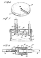
- Figure 6 is a perspective view of a disc-shaped flow control device and/or filter according to the invention, as used in the embodiment of Figure 7.
- Figure 7 is a fragmentary side elevational view, in section, showing a valve and/or filter assembly inside the receptacle and using the disc- shaped valve member of Figure 6 as the operative element.
- Figure 8 is a vertical sectional view showing a valve and/or filter assembly in series in the vacuum line and using the device shown in Figure 5.
- Figure 1 shows the site 10 at which a surgical operation has been performed upon a patient, and a patient tube 12 which leads from that site to the inlet fitting 13 to aspirate liquids, including any gases or small particles carried by the liquid, from the site of the operation to the nearby liquid-collecting system 14.
- a vacuum source 16 such as a hospital vacuum line, provides a suitable vacuum which normally acts through the vacuum line 18 and the liquid-collecting system 14 to produce suction at the free or aspirating end of the patient tube 12.
- An air check valve 20 may be included in series with the vacuum line. If desired, a suitable pinch valve can be provided near the aspirating end of the patient tube so that medical personnel may easily turn the aspirating action on and off at will.
- a receptacle 24 in the form of a flexible plastic bag, the top opening of which is sealed to a lower surface of a solid plastic lid 28.
- the seal between receptacle 24 and lid 28 may be provided by any suitable air-impervious adhesive.
- the hollow, tubular, inlet fitting 13 extends through and above and below the lid, as does the hollow, tubular, outlet fitting 36.
- the flow control device 37 constructed in accordance with the invention is mounted on the end of outlet fitting 36 which lies within the receptacle 24, as by forcing it onto the nipple end 38 of the latter fitting, as shown more clearly in Figure 4.
- the receptacle 24 is disposed within a canister 40, which may be of rigid plastic or metal and which provides mechanical support and protection for the bag assembly as well as support for a pressure-equalizing connector 41 used as described hereinafter to equalize the air pressure inside and immediately outside of the receptacle 24.
- a downwardly-extending rim portion 42 is provided on the lid 28 which can be readily snapped into air-tight relation with the top of the canister to complete the assembly of receptacle and canister and to enable later easy removal and discard of bag and lid.
- T-connector 41 provides communication at 52 between the vacuum line and the interior of the canister, so that as the vacuum line is evacuated, and the interior of the bag 24 therefore also evacuated, a correspondingly reduced air pressure is produced within the canister outside of the bag so the bag will not be subject to collapse during operation.
- the portion of the vacuum line 18 extending from the air outlet 36 on lid 28 is connected to the T-connector 41 as shown to complete the operative assembly.
- liquids will be aspirated through the patient tube 12 and the inlet fitting 13 into the interior of the receptacle 24 where they will fall to the bottom of the bag and accumulate as shown in Figure 3.
- the flow control device of the invention When they have accumulated to the level shown in Figure 4, the flow control device of the invention will be covered with the accumulated liquid, as a result of which it will become substantially impervious to the flow of gas or liquid through it. This therefore terminates the aspiration be fore the accumulated liquid reaches the level at which undesired overflow from the outlet fitting can occur.
- suitable indicator or alarm means can be provided to indicate when this condition has been reached.
- the patient tube 12 can then be disconnected from the lid 28, the vacuum line 18 is disconnected from the outlet fitting 36, the lid 28 and the appended filled bag removed from the canister 40, and the lid and bag assembly discarded. It will therefore be seen that filling of the bag is automaticallly terminated as desired, without requiring the use of any moving parts or other complicated mechanism.
- Figure 5 shows particular form for the filter and valve device itself, although it may take any of a large variety of different configurations in different applications.
- it is in the form of a cylinder which has a dead-ended central bore 60 providing an end wall 62, so that the aspirated air must pass through a wall of the device to reach the interior of the outlet fitting 36, which terminates inside bore 60 as shown in Figure 3.
- this form of the flow control device of the present invention is shown for use within the receptacle of an aspirating device, it can be used also in an aspirating device of the type in which the flow control device is located outside of the receptacle, for example, in an outlet line leading from the outlet of the receptacle to the vacuum source.
- the form of the device shown in Figure 5 is preferred for use as an "external" flow control device, for example, as shown in Figure 8.
- the flow-control assembly 140 is shown placed in series in the vacuum line 18 which extends from the outlet fitting 36 to the vacuum source 16 in Figure 1.
- the flow device itself may be the same valve cylinder 37, with a central dead-ended bore 60, as is shown in Figure 5.
- a circumferentially-ribbed, hollow, tubular stem 144 extends snugly into the bore 60, and communicates with a central opening in the outlet tube 148 which is integral with stem 144.
- a circular flange 150 also integral with the stem and the tube, extends radially at the junction of stem and tube.
- An outer cylindrical casing 160 fits tightly about, and may be cemented to, a corresponding circular ledge 162 extending about the periphery of the flange, so that the outer cylindrical casing 160 surrounds the valve cylinder 37 at a radial distance therefrom.
- the opposite end of the outer cylindrical casing is closed by a circular end wall 170 having a central opening 172 communicating with the interior of an inlet tube 178 which extends outwardly therefrom.
- Inlet tube 178 also extends slightly into the outer cylindrical casing 160, is closed at its interior end, and has an opening 179 in its sidewall adjacent its interior end, so that the flow of air into the casing 160 will be diffused and distributed, rather than concentrated on the adjacent end of the valve cylinder. All parts of the assembly may be made of a transparent polyacrylic material, as an example.
- Figure 6 shows a particularly preferred form of a flow control device for use within the receptacle of an aspirating device, for example, as shown in the embodiment of Figure 7, in which the flow control assembly 100 is located inside the receptacle 24.
- This assembly uses a valve in the form of the disc 102 of Figure 6, which is pressed into a circular recess 104 in the underside of the disc-supporting cup 106 until a marginal area of the upper side of the disc bears against the bottom of the internal ring-like band 108 in cup 106, to form a seal therewith; the internal sidewalls 109 of the lower portion of the cup are tapered slightly inwardly along the upward direction, and the disc is inserted with the boss 110 positioned upwardly so that the inwardly-slanted portions 111 of the edge of the disc mate with the inwardly-slanted internal sidewalls of the cup 106.
- the disc may be solvent-welded to the inner side walls of the cup into which it is thus placed.
- a plastic retaining ring 112 may then be formed by heat-knurling the bottom end of the cup to bridge the space between the bottom of the cup and the marginal portions of the lower side of the disc, thereby to secure the disc positively in place.
- the cup is also provided with a top opening 116 communicating with an integral upwardly-extending tube 120.
- the latter tube is slipped over the outside of a downwardly-depending hollow nipple 122 formed integrally on the underside of lid 28', and is cemented or otherwise secured thereto.
- the opening in the nipple is aligned with an opening 124 extending through the lid 28' and communicating with the interior of the upwardly-extending tubular outlet fitting 36'.
- the flow control device of the present invention comprises a material which is capable of absorbing a relatively large amount of water, for example, at least about 50 parts by weight of water per part by weight of material.
- the highly water-absorbent material should resist being affected adversely as a result of contact with blood, body fluids, medications and other materials which may be encountered in such an aspirating application.
- the highly water-absorbent material should not be a source of contamination of the material which is collected in the receptacle of the collecting system. In situations where it is desired to analyze the collected materials, contamination thereof cannot be tolerated.
- species of water insoluble, highly water-absorbent materials which can be used in the practice of the present invention comprise synthesized resins, including, for example, chemically treated naturally occurring polymeric materials and synthetic polymeric materials prepared by polymerization of monomers.
- An exemplary class of materials prepared from chemically treating naturally occurring polymeric materials comprise those which are synthesized from naturally occurring polymeric materials such as, for example, carboxymethylcelluloses, polysaccharides such as, for example, starch, and natural gums such as, for example, guar gum, and from vinyl compounds which are reactive therewith.
- the water-absorbent polymer described therein is prepared by hydrolyzing a starch/polyacrylonitrile graft copolymer, the hydrolysis being effected by treating the polymer with an aqueous solution of an alkaline material or base, for example, potassium hydroxide to form a carboxylate.
- an alkaline material or base for example, potassium hydroxide
- the hydrolyzed form of the graft copolymer is characterized as containing both carboxyl and amide groups.
- Addition of acid to the carboxylate forms the free acid which in turn can be precipitated from an alcohol solution.
- 3,661,815 discloses that the water-absorbing properties of resins disclosed in the aforementioned '971 patent are reduced upon contact with urine, and that this problem can be overcome by conducting the aforementioned type of hydrolytic reaction or saponification with an alkaline solution that includes alcohol.
- Aforementioned U.S. Patent No. 3,997,484 discloses that the water-absorbing properties of a hydrolyzed graft starch/polyacrylonitrile resin or starch/polymethacrylonitrile can be increased by using gelatinizing starch to prepare the graft copolymer. Insoluble resin can be obtained by evaporating the aqueous alkaline solution that is used in the hydrolytic or saponifying step.
- 4,076,663 discloses the preparation of a water-absorbent resin prepared by polymerizing the following monomers: (A) starch or cellulose; (B) at least one monomer having a polymerizable double bond which is water-soluble or becomes water-soluble by hydrolysis; and (C) a cross-linking agent; and, if necessary, subjecting the resulting product to hydrolysis.
- 4,302,369 discloses that problems are encountered when highly water-absorbent resins are subjected to water which contains free ions, for example, sodium, and that such problems can be overcome by reacting the hydrolyzed form of a starch or gelatinized starch/acrylonitrile graft copolymer with aluminum to produce an aluminum salt of the copolymer. Such resins are said to have an enhanced degree of wicking and over-all improved water-absorbing properties.
- Exemplary water-absorbing properties of resins which are the subjects of said patents have the capability of absorbing about 50 to about 1000 parts or more of water per part of resin.
- Such resins can be produced in water-insoluble granular form and have the ability to absorb such large amounts of water while retaining their granular form.
- Various of the aforementioned patents disclose that water-absorbing resins of the type disclosed therein can be used in many types of applications including, for example, as water or body-fluid absorbents in diapers, sanitary napkins, bed or surgical pads, and disposable dust cloths, and to increase the water-holding capacity of soils, and as coatings for seeds, clay, starch, fibers, paper and the like.
- 4,421,129 discloses the use of such resins in preparing shaped articles which can be used to rapidly dry hair.
- articles include combs, hair brushes, and hair curlers which are made by molding a powdery form of the highly water-absorbent polymer in a mold under pressure and at ambient temperature.
- Such articles take advantage of those proper ties of the water-absorbent resin by which large quantities of water are quickly absorbed in a short time, for example, within minutes, without causing a change in the gross shape of the article.
- the rate at which absorbed water evaporates from the resin varies depending on the resin, the evaporation rate for some resins being substantially the same as that of water of similar surface area. As water evaporates from the resin, it is capable of being reused to absorb water.
- water insoluble, highly water-absorbent materials other than the graft starch polymers mentioned above can be used in the practice of the present invention.
- resins include cross-linked poly(alkylene oxide) resins, cross-linked polyacrylate resins, and cross-linked carboxy methylcellulose resins. Species of such resins are known and include materials which are available commercially. The following U.S. patents disclose examples of additional species of water-absorbent resins: Nos. 3,264,202; 3,898,143 and 3,956,224.
- water-absorbent resins examples include the following trademark products sold by Grain Processing Corporation: Water-Lock A-100 characterized as being insoluble in most organic solvents, resistant to body fluid enzymes and capable of absorbing dilute aqueous acid and alkali solutions, and having the ability to absorb at least 110 ml of water/g of resin; Water-Lock J-500 characterised as being capable of absorbing at least about 500 ml of water/g of resin; and Water-Lock J-550 characterised as being capable of absorbing at least 375 ml of water/g of resin.
- Water-Lock A-100 characterized as being insoluble in most organic solvents, resistant to body fluid enzymes and capable of absorbing dilute aqueous acid and alkali solutions, and having the ability to absorb at least 110 ml of water/g of resin
- Water-Lock J-500 characterised as being capable of absorbing at least about 500 ml of water/g of resin
- Water-Lock J-550 characterised as being capable of absorbing at least
- Such resins are described by their manufacturer as being super absorbent products which are prepared by hydrolyzing starch/acrylonitrile graft copolymers to form polymeric products having side chains which contain carboxamide and carboxylate groups.
- the aforementioned resins are available commercially as free flowing powders.
- Other sources of the resins include Arakawa Chemical (U.S.A.) Inc. which sells their resins under the trademark "ARASORB”, Sanyo Chemical, Unilever, Hercules, and Dow Chemical.
- the flow control device of the present invention can be made almost entirely (and up to 99% by weight) from the water insoluble, highly water-absorbent material, together with one or more other materials, including major amounts (up to 99.5% by weight) of such other materials.
- a polyolefin having a molecular weight of at least about 900,000 and which is capable of being sintered is included, but so too may be other materials such as carriers and additives which improve the physical and/or chemical properties of the composition comprising the device.
- the composition can comprise, for example, polyethylene, acrylic resin, and nylon (to name but a few), a filler material such as calcium carbonate, lubricant, anti-oxidant, fibers, including both synthetic and natural fibers, and materials which modify one or more of the asthetic, physical and chemical properties of the composition, for example molybdenum disulfide.
- the polyolefin filler may comprise a polyethylene or a polypropylene.
- An attractive feature of the present invention is that relatively small amounts of the highly water-absorbent resin can be used in fabricating the flow-control device. Thus, a minor amount of the resin can be combined with a major amount of the carrier or filler material(s), including material(s) which is less costly than the water-absorbent resin.
- the strength of the device can be improved by the use of a carrier material, preferred materials being polyethylenes, and polypropylenes having a molecular weight of at least about 900,000 to several million.
- melt index of such polymeric materials be less than 1.
- polyethylenes having a molecular weight of at least about 2.5 million and a melt index below 1 are particularly desirable material for use in the present invention.
- Recommended commercial products are those sold under the trademark HOSTALEN GUR and HIMONT, for example HOSTALEN GUR 412, 413, and 415, and HIMONT HB 312.
- the amount of water-absorbent resin comprising the fluid-control device can vary over a wide range, the minimum amount being dictated by that needed to block the passage of the aqueous fluid through the device as it is contacted therewith, and the maximum amount being about 100 wt.% of the resin.
- a device within the present invention can comprise about 0.5 to about 99 wt.% of the water-absorbent resin and about 1 to about 99.5 wt.% of filler.
- Preferred amounts of constituents comprise about 5 to about 15 wt.% resin and about 85 to about 95 wt.% filler.
- the device of the present invention can be made in various ways, including, for example, by the method disclosed in aforementioned U.S. Patent No. 4,421,129 for fabricating the hair drying devices described therin.
- This method involves basically forming the article by injection or compression molding techniques utilizing elevated pressures and ambient temperature.
- powdered resin is placed into a hardened steel mold and formed into an article of the desired shape at pressures of about 200 to about 40,000 psi at ambient temperature and within one minute. Elevated temperatures can be used also in the molding operation.
- a fluid-control device as shown in Figure 5 was made in the following manner.
- the device had an overall length of 2.1 inches, a bore length of 1.9 inches, an overall diameter of 0.69 inch and a bore diameter of 0.295 inch.
- the device was fabricated from a composition comprising: (A) 90 wt.% of powdered polyethylene having a molecular weight of about 3.5 million, a melt index below 1, and a spherical particle size diameter of about 50 microns; and (B) 10 wt.% of highly water-absorbent resin particles comprising a hydrolyzed form of a starch/acrylonitrile copolymer sold by Grain Processing Corporation under the trademark Water-Lock A-200.
- the resin and polyethylene particles were ball-milled to produce a mixture in which particles of the water-absorbent resin were adhered to the larger size particles of polyethylene.
- the resin mixture was placed into an approximately shaped mold and then made into the fluid-control device by compression molding at a temperature of about 375°F and a pressure of about 1000 psi, and for a time of about 10-15 minutes.
- the device had a pore size of about 5 microns. Evaluating work showed that the device was capable of: (A) filtering 99.8% of bacteria as small as Pseudomonas diminutae and 100% of larger bacteria; and (B) holding fluids of the type collected in the receptacle of the collecting system described above for in excess of 8 hours.
- the fluid-control device of Examle 1 immediately upon being wetted with the liquid contents of the receptacle prevented passage thereof beyond the device. It has been observed that foam generated from materials such as blood, soap and egg whites do not adversely affect the function of the device, nor does it cause a slow down or premature termination of air flowing there through. It has been observed also that, in use, the flow-control device of Example 1 permitted the passage therethrough of laser plume with minimal air flow restrictions. The device was used in an application which included an initial air flow in the range of about 3.6 to about 5 cubic ft/min and with air flow at the patient site being no less than about 2.6 cubic ft/min, a satisfactory value.
- a flow-control device as shown in Figure 5 and described in Example 1 is made, as described in Example 1, but with somewhat different dimensions, the device being contemplated for use as an "external" filter/valve in an aspirating device.
- the device has an overall length of 1.7 inches, a bore length of 1.5 inches, an overall diameter of 1 inch and a bore diameter of 0.6 inch.
- the flow-control device has a uniform porosity of about 9.75 micron pore radius and a pore volume of about 50%. It is capable of operating at a source vacuum of about 3 SCFM (24'' Hg) with an air flow of no less than about 2.5 SCFM - even when exposed to laser plume for 2 hours.
- the flow-control device is capable also of not permitting any fluid to pass through it for at least 8 hours.
- Filtering characteristics include the ability of filtering more than 99% of Pseudomonas diminutae and 100% of Micrococcus luteus and B. subtilis .
- a flow control device in the form of a disc is made from a composition like that described in Example 1 and in the manner described in Example 1.
- the diameters of the lower and upper surfaces of the disc are respectively 2.43 and 2.40 inches.
- the thickness of the disc is 0.2 inch.
- the inwardly slanted portions of the edge of the disc are inclined at an angle of 5°, with the slanted portions beginning at a distance of 0.05 inch from the lower surface of the disc.
- the porosity and pore volume of the device are like those of the device of Example 2 and its operating characteristics are also like those of the device of Example 2.
- the embodiments described above are shown for use in apparatus for aspirating body fluids from the site of a body wound.
- the apparatus which is illustrated functions by virtue of the use of reduced pressure or vacuum which draws liquid away from the body and into the apparatus.
- Devices within the scope of the present invention can be used also in other types of applications involving the use of a vacuum pump to protect the pump from undesired contact with fluids. It should be understood that devices within the scope of the present invention can be used also in other types of applications, including, for example, applications in which gas flow through the device is under positive pressure.
Landscapes
- Health & Medical Sciences (AREA)
- Heart & Thoracic Surgery (AREA)
- Hematology (AREA)
- Engineering & Computer Science (AREA)
- Anesthesiology (AREA)
- Biomedical Technology (AREA)
- Vascular Medicine (AREA)
- Life Sciences & Earth Sciences (AREA)
- Animal Behavior & Ethology (AREA)
- General Health & Medical Sciences (AREA)
- Public Health (AREA)
- Veterinary Medicine (AREA)
- External Artificial Organs (AREA)
- Media Introduction/Drainage Providing Device (AREA)
Abstract
Claims (11)
- Valve poreuse non-mécanique, dont les passages internes qui la traversent ont, avant mouillage par un liquide aqueux, une aire de section transversale suffisamment grande pour permettre l'écoulement de gaz et de liquide à travers ceux-ci, et comprenant :A - un matériau résineux insoluble dans l'eau, capable de gonfler en réponse à son mouillage par ledit liquide aqueux de façon à fermer sensiblement complètement les passages lorsque la valve est mouillée tandis que la forme extérieure et le volume brut de la valve sont conservés, de façon à empêcher ensuite l'écoulement de gaz et de liquide à travers la valve ; etB - une charge résineuse ;la valve étant caractérisée par une structure comprenant le produit fritté formé de 0,5 à 99 % en poids d'une résine insoluble dans l'eau, absorbant l'eau, et capable d'absorber au moins 50 g d'eau/g de résine, et 1 à 99,5 % en poids d'une polyoléfine ayant un poids moléculaire d'au moins environ 900 000 et qui est capable d'être frittée.
- Valve selon la revendication 1, caractérisée en ce que ladite polyoléfine consiste essentiellement en du polyéthylène ou polypropylène ayant un indice de fusion inférieur à 1.
- Valve selon la revendication 2, caractérisée en ce que ladite polyoléfine consiste essentiellement en un polyéthylène ayant un poids moléculaire d'au moins 2,5 millions.
- Valve selon la revendication 3, caractérisée en ce que ladite structure comprend 5 à 15 % en poids de ladite résine et 85 à 95 % en poids dudit polyéthylène.
- Valve selon l'une quelconque des revendications 1 à 4, caractérisée en ce que ladite résine absorbant l'eau est capable d'absorber au moins 100 parties d'eau/partie de résine et de conserver l'eau absorbée pendant au moins quatre heures.
- Composition capable d'être frittée et formée en la valve de l'une quelconque des revendications 1 à 5, caractérisée par le mélange non fritté de ladite résine insoluble dans l'eau et absorbant l'eau, et de ladite polyoléfine.
- Système de valve pour commander automatiquement l'écoulement qui la traverse, comprenant :A - la valve de l'une quelconque des revendications 1 à 5 ;B - des moyens pour fournir du gaz à une première pression en une première région de ladite valve tout en maintenant une seconde pression de gaz, plus basse, en une autre région de ladite valve ; etC - des moyens pour monter ladite valve dans une position dans laquelle la partie de celle-ci entre lesdites première et autre régions de celle-ci est soumise à mouillage par un liquide aqueux.
- Système de valve selon la revendication 7, caractérisé en ce que lesdites aires de section transversale des passages de la valve, avant mouillage, sont suffisamment petits pour que cette valve serve de filtre bactériologique.
- Système de valve selon la revendication 9, caractérisé en ce que la taille desdits passages est telle que des bactéries ayant la taille de bactéries Pseudomonas dimunutae et de bactéries de plus grande taille sont empêchées de traverser la valve.
- Système de valve selon l'une quelconque des revendications 7 à 9, caractérisé en ce que ladite polyoléfine consiste essentiellement en un polyéthylène ayant un poids moléculaire d'au moins 2,5 millions.
- Système d'aspiration pour ôter des liquides du voisinage d'un corps vivant, comprenant une source de vide, un tube aspirateur dont une première extrémité est adaptée à être placée dans le voisinage immédiat dudit corps pour en aspirer des liquides, un réceptacle collecteur de liquide ayant une sortie d'air et une entrée, des premiers moyens reliant l'autre extrémité du tube aspirateur à ladite entrée, une ligne d'aspiration reliant fonctionnellement ladite source de vide à ladite sortie d'air, ladite entrée et ladite sortie étant toutes deux écartées du fond du réceptacle de sorte que le réceptacle peut être empli dudit liquide jusqu'à une hauteur substantielle avant que le niveau de ce liquide atteigne ladite entrée et ladite sortie ; des moyens étant prévus pour empêcher le liquide collecté de sortir de ladite sortie d'air du réceptacle et d'aller au-delà d'un point prédéterminé dans la ligne d'aspiration, ces moyens étant un organe de commande d'écoulement normalement perméable aux gaz et aux liquides, positionné dans le trajet du liquide collecté entre un point à l'intérieur du réceptacle et ledit point prédéterminé dans la ligne d'aspiration, caractérisé en ce que ledit organe de commande d'écoulement comprend la valve de l'une quelconque des revendications 1 à 5.
Applications Claiming Priority (3)
| Application Number | Priority Date | Filing Date | Title |
|---|---|---|---|
| US75542885A | 1985-07-16 | 1985-07-16 | |
| US755428 | 1985-07-16 | ||
| PCT/US1986/001502 WO1987000439A1 (fr) | 1985-07-16 | 1986-07-14 | Dispositif de commande de l'ecoulement d'un fluide et appareil l'utilisant |
Publications (3)
| Publication Number | Publication Date |
|---|---|
| EP0228466A1 EP0228466A1 (fr) | 1987-07-15 |
| EP0228466A4 EP0228466A4 (fr) | 1989-02-22 |
| EP0228466B1 true EP0228466B1 (fr) | 1995-08-30 |
Family
ID=25039107
Family Applications (1)
| Application Number | Title | Priority Date | Filing Date |
|---|---|---|---|
| EP86904697A Expired - Lifetime EP0228466B1 (fr) | 1985-07-16 | 1986-07-14 | Dispositif de commande de l'ecoulement d'un fluide et appareil l'utilisant |
Country Status (5)
| Country | Link |
|---|---|
| EP (1) | EP0228466B1 (fr) |
| JP (1) | JPS63500571A (fr) |
| CA (1) | CA1284073C (fr) |
| DE (1) | DE3650380T2 (fr) |
| WO (1) | WO1987000439A1 (fr) |
Cited By (1)
| Publication number | Priority date | Publication date | Assignee | Title |
|---|---|---|---|---|
| DE102014000831A1 (de) * | 2014-01-23 | 2015-07-23 | Olympus Winter & Ibe Gmbh | Küken eines Absperrhahnes eines chirurgischen Instrumentes |
Families Citing this family (39)
| Publication number | Priority date | Publication date | Assignee | Title |
|---|---|---|---|---|
| IE901130A1 (en) * | 1989-03-30 | 1991-02-13 | Abbott Lab | Suction drainage infection control system |
| DE69008600T2 (de) * | 1989-03-30 | 1994-08-25 | Abbott Lab | Absaugvorrichtung mit einer Einrichtung zur Infektionsvermeidung. |
| EP0391219B1 (fr) * | 1989-03-30 | 1993-09-01 | Abbott Laboratories | Dispositif de drainage par aspiration et moyens limitant les risques d'infection |
| DE69011176T2 (de) * | 1989-03-30 | 1994-12-08 | Abbott Lab | Absaugvorrichtung mit einer Einrichtung zur Infektionsvermeidung. |
| US5122167A (en) * | 1989-12-26 | 1992-06-16 | Skd Pneumatics Inc. | Free-flow gas filter assembly |
| US7198046B1 (en) | 1991-11-14 | 2007-04-03 | Wake Forest University Health Sciences | Wound treatment employing reduced pressure |
| JP3618755B2 (ja) * | 1993-12-27 | 2005-02-09 | アボツト・ラボラトリーズ | 吸入排液装置の過剰充填防止 |
| US5522910A (en) * | 1994-09-09 | 1996-06-04 | Fogal, Sr.; Robert D. | End-line compressed air moisture filter |
| KR20010057392A (ko) * | 1999-12-22 | 2001-07-04 | 김형벽ㅂ | 시엔시 가스 커팅 머신 |
| FR2824255B1 (fr) | 2001-05-07 | 2004-02-06 | Imv Technologies | Paillette pour la conservation de petites quantites de substances, notamment de liquides biologiques |
| FR2824256B1 (fr) * | 2001-05-07 | 2004-04-02 | Imv Technologies | Paillette pour la conservation de petites quantites de substances, en particulier de liquides biologiques |
| US6780309B2 (en) * | 2002-03-22 | 2004-08-24 | Allegiance Corporation | Tapered hydrophobic filter for suction canisters |
| US8141717B2 (en) | 2006-08-18 | 2012-03-27 | Porex Corporation | Sintered polymeric materials and applications thereof |
| DE602007004546D1 (de) | 2006-09-28 | 2010-03-18 | Tyco Healthcare | Tragbares Wundtherapiesystem |
| US7931651B2 (en) | 2006-11-17 | 2011-04-26 | Wake Lake University Health Sciences | External fixation assembly and method of use |
| US8377016B2 (en) | 2007-01-10 | 2013-02-19 | Wake Forest University Health Sciences | Apparatus and method for wound treatment employing periodic sub-atmospheric pressure |
| US8187534B2 (en) | 2007-02-12 | 2012-05-29 | Porex Corporation | Porous barrier media comprising color change indicators |
| GB0712763D0 (en) | 2007-07-02 | 2007-08-08 | Smith & Nephew | Apparatus |
| EP2205189B1 (fr) | 2007-10-10 | 2017-12-06 | Wake Forest University Health Sciences | Dispositifs de traitement d'un tissu de moelle épinière |
| GB0803564D0 (en) | 2008-02-27 | 2008-04-02 | Smith & Nephew | Fluid collection |
| US8267909B2 (en) * | 2008-05-01 | 2012-09-18 | Devilbiss Healthcare, Llc | Canister having fluid flow control |
| US8177763B2 (en) | 2008-09-05 | 2012-05-15 | Tyco Healthcare Group Lp | Canister membrane for wound therapy system |
| US10912869B2 (en) | 2008-05-21 | 2021-02-09 | Smith & Nephew, Inc. | Wound therapy system with related methods therefor |
| US8414519B2 (en) | 2008-05-21 | 2013-04-09 | Covidien Lp | Wound therapy system with portable container apparatus |
| AU2009256128B2 (en) * | 2008-06-04 | 2013-07-04 | Solventum Intellectual Properties Company | Reduced-pressure, liquid-collection canister with multi-orientation filter |
| CA2730362C (fr) | 2008-07-18 | 2018-07-10 | Wake Forest University Health Sciences | Appareil et procede pour la modulation du tissu cardiaque par application topique de vide afin de reduire au minimum la mort et les dommages cellulaires |
| US8827983B2 (en) | 2008-08-21 | 2014-09-09 | Smith & Nephew, Inc. | Sensor with electrical contact protection for use in fluid collection canister and negative pressure wound therapy systems including same |
| DE102011009759A1 (de) * | 2011-01-28 | 2012-08-02 | Atmos Medizintechnik Gmbh & Co. Kg | Absaugvorrichtung |
| US8690981B2 (en) | 2011-06-15 | 2014-04-08 | Porex Corporation | Sintered porous plastic liquid barrier media and applications thereof |
| JP6076367B2 (ja) * | 2011-11-03 | 2017-02-08 | ポレックス コーポレーション | 医療用吸引装置のための疎水性多孔質の非機械的弁 |
| GB2523591B (en) | 2014-02-28 | 2016-03-30 | Aspirate N Go Ltd | Aspirators |
| EP3659638B1 (fr) | 2014-07-31 | 2026-01-07 | Smith & Nephew, Inc. | Systèmes et procédés pour la mise en uvre d'une thérapie par pression réduite |
| US12133789B2 (en) | 2014-07-31 | 2024-11-05 | Smith & Nephew, Inc. | Reduced pressure therapy apparatus construction and control |
| DE102016212672B3 (de) * | 2016-07-12 | 2017-07-06 | Olympus Winter & Ibe Gmbh | Einrichtung zum Prüfen der Dichtigkeit eines chirurgischen Instruments, Aufbereitungseinrichtung zum Aufbereiten von chirurgischen Instrumenten und Verwendung eines quellbaren Materialkörpers |
| JP6361844B1 (ja) * | 2016-09-23 | 2018-07-25 | 株式会社村田製作所 | 陰圧閉鎖療法器具 |
| WO2018195101A1 (fr) | 2017-04-19 | 2018-10-25 | Smith & Nephew, Inc. | Cartouches pour traitement de plaies par pression négative |
| DE102019006226A1 (de) * | 2019-09-04 | 2021-03-04 | Drägerwerk AG & Co. KGaA | Auffang-Anordnung mit einer Filter-Anordnung zum Aufnehmen von abgesondertem Sekret |
| GB201914283D0 (en) | 2019-10-03 | 2019-11-20 | Smith & Nephew | Apparatuses and methods for negative pressure wound therapy |
| US11771819B2 (en) * | 2019-12-27 | 2023-10-03 | Convatec Limited | Low profile filter devices suitable for use in negative pressure wound therapy systems |
Family Cites Families (8)
| Publication number | Priority date | Publication date | Assignee | Title |
|---|---|---|---|---|
| US3661815A (en) * | 1970-05-18 | 1972-05-09 | Grain Processing Corp | Water-absorbing alkali metal carboxylate salts of starch-polyacrylonitrile graft copolymers |
| US3898143A (en) * | 1971-06-11 | 1975-08-05 | Union Carbide Corp | Process for cocrosslinking water soluble polymers and products thereof |
| GB1480334A (en) | 1973-07-09 | 1977-07-20 | Unilever Ltd | Safety valves for protection against liquid contamination |
| JPS51125468A (en) * | 1975-03-27 | 1976-11-01 | Sanyo Chem Ind Ltd | Method of preparing resins of high water absorbency |
| US4228798A (en) * | 1979-05-01 | 1980-10-21 | Deaton David W | Suction receptacle with hygroscopic filter |
| US4328828A (en) * | 1980-09-17 | 1982-05-11 | The Kendall Company | Drainage system with vent |
| US4465485A (en) * | 1981-03-06 | 1984-08-14 | Becton, Dickinson And Company | Suction canister with unitary shut-off valve and filter features |
| JPS57190567A (en) | 1981-05-20 | 1982-11-24 | Terumo Corp | Blood sampler with air removing and shielding mechanism |
-
1986
- 1986-07-14 WO PCT/US1986/001502 patent/WO1987000439A1/fr not_active Ceased
- 1986-07-14 DE DE3650380T patent/DE3650380T2/de not_active Expired - Fee Related
- 1986-07-14 JP JP61504036A patent/JPS63500571A/ja active Pending
- 1986-07-14 EP EP86904697A patent/EP0228466B1/fr not_active Expired - Lifetime
- 1986-07-15 CA CA000513780A patent/CA1284073C/fr not_active Expired - Lifetime
Cited By (1)
| Publication number | Priority date | Publication date | Assignee | Title |
|---|---|---|---|---|
| DE102014000831A1 (de) * | 2014-01-23 | 2015-07-23 | Olympus Winter & Ibe Gmbh | Küken eines Absperrhahnes eines chirurgischen Instrumentes |
Also Published As
| Publication number | Publication date |
|---|---|
| JPS63500571A (ja) | 1988-03-03 |
| WO1987000439A1 (fr) | 1987-01-29 |
| EP0228466A4 (fr) | 1989-02-22 |
| DE3650380D1 (de) | 1995-10-05 |
| DE3650380T2 (de) | 1996-05-15 |
| CA1284073C (fr) | 1991-05-14 |
| EP0228466A1 (fr) | 1987-07-15 |
Similar Documents
| Publication | Publication Date | Title |
|---|---|---|
| EP0228466B1 (fr) | Dispositif de commande de l'ecoulement d'un fluide et appareil l'utilisant | |
| US20240009372A1 (en) | Canister for a negative pressure wound therapy system | |
| US4459139A (en) | Disposable filter device and liquid aspirating system incorporating same | |
| CA2166127C (fr) | Traitement de gelification pour systeme de drainage aspiratif | |
| EP2300069B1 (fr) | Dispositif portable de therapie de plaies a pression negative | |
| US5466229A (en) | Fluid collection system | |
| EP0390095B1 (fr) | Dispositif de drainage par aspiration et moyens limitant les risques d'infection | |
| EP0205614B1 (fr) | Systeme de drainage de blessures ayant un tampon de blocage de lipides | |
| US6780309B2 (en) | Tapered hydrophobic filter for suction canisters | |
| EP2925379B1 (fr) | Boîte d'aspiration comprenant une cartouche de filtre remplaçable | |
| US5238582A (en) | Method of treating waste liquid | |
| CA2096939C (fr) | Poche de drainage contenant un materiau absorbant, et son mode d'utilisation | |
| EP0394687B1 (fr) | Dispositif de drainage par aspiration et moyens limitant les risques d'infection | |
| JP4167534B2 (ja) | 液状廃棄物処理装置 | |
| EP0786979A1 (fr) | Systeme pour recueillir des fluides |
Legal Events
| Date | Code | Title | Description |
|---|---|---|---|
| PUAI | Public reference made under article 153(3) epc to a published international application that has entered the european phase |
Free format text: ORIGINAL CODE: 0009012 |
|
| AK | Designated contracting states |
Kind code of ref document: A1 Designated state(s): DE FR GB IT SE |
|
| 17P | Request for examination filed |
Effective date: 19870721 |
|
| A4 | Supplementary search report drawn up and despatched |
Effective date: 19890222 |
|
| 17Q | First examination report despatched |
Effective date: 19901009 |
|
| GRAA | (expected) grant |
Free format text: ORIGINAL CODE: 0009210 |
|
| AK | Designated contracting states |
Kind code of ref document: B1 Designated state(s): DE FR GB IT SE |
|
| PG25 | Lapsed in a contracting state [announced via postgrant information from national office to epo] |
Ref country code: IT Free format text: LAPSE BECAUSE OF FAILURE TO SUBMIT A TRANSLATION OF THE DESCRIPTION OR TO PAY THE FEE WITHIN THE PRE;WARNING: LAPSES OF ITALIAN PATENTS WITH EFFECTIVE DATE BEFORE 2007 MAY HAVE OCCURRED AT ANY TIME BEFORE 2007. THE CORRECT EFFECTIVE DATE MAY BE DIFFERENT FROM THE ONE RECORDED.SCRIBED TIME-LIMIT Effective date: 19950830 |
|
| REF | Corresponds to: |
Ref document number: 3650380 Country of ref document: DE Date of ref document: 19951005 |
|
| PG25 | Lapsed in a contracting state [announced via postgrant information from national office to epo] |
Ref country code: SE Effective date: 19951130 |
|
| ET | Fr: translation filed | ||
| PLBE | No opposition filed within time limit |
Free format text: ORIGINAL CODE: 0009261 |
|
| STAA | Information on the status of an ep patent application or granted ep patent |
Free format text: STATUS: NO OPPOSITION FILED WITHIN TIME LIMIT |
|
| PGFP | Annual fee paid to national office [announced via postgrant information from national office to epo] |
Ref country code: GB Payment date: 19960716 Year of fee payment: 11 |
|
| PGFP | Annual fee paid to national office [announced via postgrant information from national office to epo] |
Ref country code: DE Payment date: 19960722 Year of fee payment: 11 |
|
| PGFP | Annual fee paid to national office [announced via postgrant information from national office to epo] |
Ref country code: FR Payment date: 19960724 Year of fee payment: 11 |
|
| 26N | No opposition filed | ||
| PG25 | Lapsed in a contracting state [announced via postgrant information from national office to epo] |
Ref country code: GB Free format text: LAPSE BECAUSE OF NON-PAYMENT OF DUE FEES Effective date: 19970714 |
|
| GBPC | Gb: european patent ceased through non-payment of renewal fee |
Effective date: 19970714 |
|
| PG25 | Lapsed in a contracting state [announced via postgrant information from national office to epo] |
Ref country code: FR Free format text: LAPSE BECAUSE OF NON-PAYMENT OF DUE FEES Effective date: 19980331 |
|
| PG25 | Lapsed in a contracting state [announced via postgrant information from national office to epo] |
Ref country code: DE Free format text: LAPSE BECAUSE OF NON-PAYMENT OF DUE FEES Effective date: 19980401 |
|
| REG | Reference to a national code |
Ref country code: FR Ref legal event code: ST |