EP0228470A1 - Echangeur de chaleur - Google Patents
Echangeur de chaleur Download PDFInfo
- Publication number
- EP0228470A1 EP0228470A1 EP86903591A EP86903591A EP0228470A1 EP 0228470 A1 EP0228470 A1 EP 0228470A1 EP 86903591 A EP86903591 A EP 86903591A EP 86903591 A EP86903591 A EP 86903591A EP 0228470 A1 EP0228470 A1 EP 0228470A1
- Authority
- EP
- European Patent Office
- Prior art keywords
- heat exchanger
- projections
- openings
- end cover
- fluid
- Prior art date
- Legal status (The legal status is an assumption and is not a legal conclusion. Google has not performed a legal analysis and makes no representation as to the accuracy of the status listed.)
- Granted
Links
Images


Classifications
-
- F—MECHANICAL ENGINEERING; LIGHTING; HEATING; WEAPONS; BLASTING
- F28—HEAT EXCHANGE IN GENERAL
- F28D—HEAT-EXCHANGE APPARATUS, NOT PROVIDED FOR IN ANOTHER SUBCLASS, IN WHICH THE HEAT-EXCHANGE MEDIA DO NOT COME INTO DIRECT CONTACT
- F28D9/00—Heat-exchange apparatus having stationary plate-like or laminated conduit assemblies for both heat-exchange media, the media being in contact with different sides of a conduit wall
-
- H—ELECTRICITY
- H05—ELECTRIC TECHNIQUES NOT OTHERWISE PROVIDED FOR
- H05K—PRINTED CIRCUITS; CASINGS OR CONSTRUCTIONAL DETAILS OF ELECTRIC APPARATUS; MANUFACTURE OF ASSEMBLAGES OF ELECTRICAL COMPONENTS
- H05K7/00—Constructional details common to different types of electric apparatus
- H05K7/20—Modifications to facilitate cooling, ventilating, or heating
- H05K7/20009—Modifications to facilitate cooling, ventilating, or heating using a gaseous coolant in electronic enclosures
- H05K7/20136—Forced ventilation, e.g. by fans
-
- F—MECHANICAL ENGINEERING; LIGHTING; HEATING; WEAPONS; BLASTING
- F28—HEAT EXCHANGE IN GENERAL
- F28D—HEAT-EXCHANGE APPARATUS, NOT PROVIDED FOR IN ANOTHER SUBCLASS, IN WHICH THE HEAT-EXCHANGE MEDIA DO NOT COME INTO DIRECT CONTACT
- F28D9/00—Heat-exchange apparatus having stationary plate-like or laminated conduit assemblies for both heat-exchange media, the media being in contact with different sides of a conduit wall
- F28D9/0025—Heat-exchange apparatus having stationary plate-like or laminated conduit assemblies for both heat-exchange media, the media being in contact with different sides of a conduit wall the conduits being formed by zig-zag bend plates
-
- F—MECHANICAL ENGINEERING; LIGHTING; HEATING; WEAPONS; BLASTING
- F28—HEAT EXCHANGE IN GENERAL
- F28F—DETAILS OF HEAT-EXCHANGE AND HEAT-TRANSFER APPARATUS, OF GENERAL APPLICATION
- F28F21/00—Constructions of heat-exchange apparatus characterised by the selection of particular materials
- F28F21/06—Constructions of heat-exchange apparatus characterised by the selection of particular materials of plastics material
- F28F21/067—Details
-
- F—MECHANICAL ENGINEERING; LIGHTING; HEATING; WEAPONS; BLASTING
- F28—HEAT EXCHANGE IN GENERAL
- F28F—DETAILS OF HEAT-EXCHANGE AND HEAT-TRANSFER APPARATUS, OF GENERAL APPLICATION
- F28F9/00—Casings; Header boxes; Auxiliary supports for elements; Auxiliary members within casings
- F28F9/02—Header boxes; End plates
-
- Y—GENERAL TAGGING OF NEW TECHNOLOGICAL DEVELOPMENTS; GENERAL TAGGING OF CROSS-SECTIONAL TECHNOLOGIES SPANNING OVER SEVERAL SECTIONS OF THE IPC; TECHNICAL SUBJECTS COVERED BY FORMER USPC CROSS-REFERENCE ART COLLECTIONS [XRACs] AND DIGESTS
- Y10—TECHNICAL SUBJECTS COVERED BY FORMER USPC
- Y10S—TECHNICAL SUBJECTS COVERED BY FORMER USPC CROSS-REFERENCE ART COLLECTIONS [XRACs] AND DIGESTS
- Y10S165/00—Heat exchange
- Y10S165/355—Heat exchange having separate flow passage for two distinct fluids
- Y10S165/399—Corrugated heat exchange plate
Definitions
- This invention relates to an improvement applicable to a plate type heat exchanger. More specifically, this invention relates to an improvement applicable to a plate type heat exchanger which is employable for cooling the inside of an electronic control cubile or the like in which electronic equipments are confined or housed.
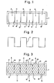
- Fig. 1 illustrates the plan view of a plate type heat exchanger which is employable for cooling the inside of an electronic control cubicle or the like.
- the plate type heat exchanger does not comprise a chamber which is flown alternately with a cooling fluid and a fluid to be cooled, but comprises a combination of a cooling fluid path and a cooled fluid path.
- the cooling fluid path is continuously flown with a cooling fluid and the cooled fluid path is continuously flown with a fluid to be cooled, thereby the cooling fluid cools the fluid to be cooled through a wall which separates the cooling fluid path and the cooled pluid path.
- This heat exchanger has an advantage to effectively protect the inside of an electronic control cubicle from a potential contamination by dusts, harmful chemical materials, et al.
- the numeral 4 indicates tubular fluid path having a rectangular cross-section.
- a plurality of the tubes 4 each of which is stuck to each other in parallel to each other, is placed in a direction vertical to the page of the drawing.
- the tubes of which the numbers are odd are flown with for example a cooling fluid A
- the tubes of which the numbers are even are flown with for example a fluid to be cooled B, thereby heat is transmitted between the cooling fluid and the cooled fluid through walls 5 which separate the fluid paths 4 placed side by side.
- a thin metal plate 6 is formed to a rectangular wave formed plate.
- the rectangular wave formed plate 6 is inserted in an external shell 7 of the heat exchanger (a tube having a large rectanglular cross-section or a box from which the top and bottom plates are removed), before the top and bottom openings of the external shell 7 are closed with sealing members 8 of rubber or the like which are stuck to the external shell 7 with an adhesive or the like.
- the numeral 81 indicates inlets or outlets of the fluids A, B.
- the cooling fluid A and the fluid to be cooled B are respectively flown in the fluid paths 4 respectively having every other number. Namely, the cooling fluid A flows in the fluid flow paths 41, 43 and 45, and the fluid to be cooled B flows in the fluid flow paths 42, 44 and 46. In other words, the fluid flow paths having the odd numbers (or even numbers) are flown by the cooling fluid A and the fluid flow paths having the even numbers (or odd numbers) are flown by the fluid to be cooled B. Heat is exchanged between the cooling fluid A and the fluid to be cooled B through the wall of the formed thin metal plate 6.
- the other equipments necessarily attached to the plate type heat exchanger are a duct (not shown) connecting the inlets (or outlets) 81 of the fluid paths 41, 43 and 45 in which the cooling fluid A flows, each other, the duct (not shown) connecting the inlets (or outlets) 81 of the fluid paths 42, 44 and 46 in which the fluid to be cooled B flows, each other, a pushing fan (not shown), a pulling fan, et al.
- the flow directions of the cooling fluid A and the fluid to be cooled B can be freely selected. In other words, they can be either same to each other or reverse to each other.
- the plate type heat exchanger having the aforementioned structure available in the prior art is fabricated with a method comprising a step to form a thin metal plate 6 to a rectangular wave formed plate, a step to insert the thin metal plate formed to a rectangular wave formed plate 6 into an external shell 7, and a step to close the top and bottom openings of the external shell 7 with sealing members 41, 42, 43, 44, 45 and 46 of rubber or the like which are stuck to the external shell 7 with an adhesive or the like, for the purpose to produce a plurality of fluid paths 4 each of which is arranged in parallel side by side. Since sealing process inherently needs a considerable length of working time or man power, the aforementioned method for fabricating a plate type heat exchanger is involved with a drawback wherein the manufacturing cost is high.
- a plate type heat exchanger illustrated in Fig. 4 and which comprises a body 1 of a formed plate having a cross-section of rectangular wave form, a top end cover 2 of a formed plate having plural top closing members 24 for closing the top openings 11 of the body 1 of which the numbers are odd (or even), and a bottom end cover 3 of a formed plate having plural bottom closing members 34 for closing the bottom openings 12 of the body 1 of which the numbers are even (or odd).
- This improved heat exchanger has successufully realized advantages that the fabrication process is easy, the hardness or strength thereof is improved in all the directions, and the construction thereof is a sort of "monocoque body", thereby the strength is sizably improved.
- this improved heat exchanger has the top and bottom end covers 2, 3 which are formed objects of thin plates, as shown in Fig. 4, the improved heat exchanger is still involved with drawbacks wherein a considerable amount of man power or working time is required to assemble the top and bottom end covers 2, 3 with the body 1, the strength is not necessarily sufficient, unless the thickness of the plates particularly of the top and bottom end covers 2, 3 is sizably large.
- An object of this invention is to provide a plate type heat exchanger comprising a body of a formed plate having a cross-section of rectangular wave form, a top end cover having plural top closing members for closing the top openings of the body of which the numbers are odd (or even), and a bottom end cover having plural bottom closing members for closing the bottom openings of the body of which the numbers are even (or odd), wherein the alignment of the body is easier, the fabrication process thereof is easier, and the strength and airtightness thereof are better.
- a heat exchanger in accordance with this invention which satisfies the aforementioned object is provided:
- a plane plate of a metal or the like is formed to a body 1 having a cross-section of rectangular wave form.
- top and bottom end covers 2, 3 having a plan view thereof shown in Fig. 6 are formed with a plastic material.
- Each of the top and bottom end covers 2, 3 has a plurality of rectangular projections 22, 32 facing the top or bottom openings 11, 12 of the body 1, and each of the rectangular projections 22, 32 is separated by a slit 21, 31 to which the top or bottom end of the plate constituting the body 1 is inserted. Every other ones of the rectangular projections 22, 32 have openings 23, 33 thereon.
- the openings 23 of the top end cover 2 face the top openings 11 of the body 1 and the openings 33 of the bottom end cover 3 face the bottom openings 12 of the body 1.
- the cross-section of the top and bottom end covers 2, 3 is made hollow to an extent in which the rigidity or strength thereof is sufficient.
- the top end of the thin metal plate which constitutes the body 1 is inserted into the slits 21 which separate the projections 22 of the top end cover 2 in the manner that the top openings 11 of the body 1 are aligned to the projections 22 of the top end cover 2, for the purpose to assemble the top end cover 2 with the body 1.
- the top openings 11 of the body 1 of which the numbers are odd (or even) must be combined with the openings 23 of the top end cover 2.
- the bottom end of the thin metal plate which constitutes the body 1 is inserted into the slits 31 which separate the projections 32 of the bottom end cover 3 in the manner that the bottom openings 12 of the body 1 are aligned to the projections 32 of the bottom end cover 3, for the purpose to assemble the bottom end cover 3 with the body 1.
- the bottom openings 12 of the body 1 of which the numbers are even (or odd) must be combined with the openings 33 of the bottom end cover 3.
- the projections 22, 32 are allowed to act as "jigs" during the aforementioned assembly process, provided the depth and width of the slits 21, 31 are selected at an optimum value, it is effective to make the assembly process easier and to enhance the magnitude of airtightness of the heat exchanger.
- Fig. 9 illustrates the front view of a complete plate type heat exchanger in accordance with one embodiment of this invention.
- the cooling fluid A is flown into the body 1 through the cooling fluid inlet 9 which is arranged at the front bottom of the body 1 of the heat exchanger, before it flows upward in the body 1 and is drafted outward by a fan 10 arranged at the front top of the heat exchanger.
- the fluid to be cooled B is flown from the inside of an electronic cubicle into the body 1 of the heat exchanger through the inlet 91 of the fluid to be cooled whcih is arranged at the rear top of the body 1 of the heat exchanger, before it flows downward in the body 1 of the heat exchanger and is drafted into the electronic cubicle through an outlet 101 arranged at the rear bottom of the heat exchanger.
- a drafting fan (not shown) can be arranged at the outlet 101.
- a plate type heat exchanger comprising a body of a formed plate having a cross-section of rectangular wave form, a top end cover having plural top closing members for closing the top openings of the body of which the numbers are odd (or even), and a bottom end cover having plural bottom closing members for closing the bottom openings of the body of which the numbers are even (or odd), wherein the alignment of the body is easier, the fabrication process thereof is easier, and the strength and airtightness thereof are better, has successfully provided.
Landscapes
- Engineering & Computer Science (AREA)
- Physics & Mathematics (AREA)
- Thermal Sciences (AREA)
- Mechanical Engineering (AREA)
- General Engineering & Computer Science (AREA)
- Microelectronics & Electronic Packaging (AREA)
- Heat-Exchange Devices With Radiators And Conduit Assemblies (AREA)
- Cooling Or The Like Of Electrical Apparatus (AREA)
Abstract
Applications Claiming Priority (2)
| Application Number | Priority Date | Filing Date | Title |
|---|---|---|---|
| JP60129138A JPS61289291A (ja) | 1985-06-15 | 1985-06-15 | 熱交換器 |
| JP129138/85 | 1985-06-15 |
Publications (3)
| Publication Number | Publication Date |
|---|---|
| EP0228470A1 true EP0228470A1 (fr) | 1987-07-15 |
| EP0228470A4 EP0228470A4 (fr) | 1987-10-08 |
| EP0228470B1 EP0228470B1 (fr) | 1990-01-17 |
Family
ID=15002055
Family Applications (1)
| Application Number | Title | Priority Date | Filing Date |
|---|---|---|---|
| EP86903591A Expired - Lifetime EP0228470B1 (fr) | 1985-06-15 | 1986-06-11 | Echangeur de chaleur |
Country Status (6)
| Country | Link |
|---|---|
| US (1) | US4739827A (fr) |
| EP (1) | EP0228470B1 (fr) |
| JP (1) | JPS61289291A (fr) |
| KR (1) | KR880700230A (fr) |
| DE (1) | DE3668369D1 (fr) |
| WO (1) | WO1986007441A1 (fr) |
Cited By (1)
| Publication number | Priority date | Publication date | Assignee | Title |
|---|---|---|---|---|
| WO2004065876A1 (fr) * | 2003-01-24 | 2004-08-05 | Behr Gmbh & Co. Kg | Echangeur thermique, notamment refroidisseur de gaz d'echappement pour automobiles |
Families Citing this family (6)
| Publication number | Priority date | Publication date | Assignee | Title |
|---|---|---|---|---|
| US4840225A (en) * | 1987-04-10 | 1989-06-20 | Digital Equipment Corporation | Heat exchange element and enclosure incorporating same |
| US5282507A (en) * | 1991-07-08 | 1994-02-01 | Yazaki Corporation | Heat exchange system |
| US7108052B2 (en) * | 2003-06-26 | 2006-09-19 | Tellabs Petaluma, Inc. | Low-cost method of forming a heat exchanger with an increased heat transfer efficiency |
| US7011148B1 (en) * | 2003-10-23 | 2006-03-14 | Tellabs Petaluma, Inc. | Heat exchanger with increased heat transfer efficiency and a low-cost method of forming the heat exchanger |
| TWM355492U (en) * | 2008-09-19 | 2009-04-21 | Asia Vital Components Co Ltd | Sealing cap structure of machine core in heat-exchange machine |
| ITTO20120355A1 (it) * | 2012-04-20 | 2013-10-21 | Mg S R L | Dispositivo scambiatore di aria a doppio flusso fra due ambienti contigui |
Family Cites Families (10)
| Publication number | Priority date | Publication date | Assignee | Title |
|---|---|---|---|---|
| DE2055255A1 (de) * | 1970-11-05 | 1972-05-10 | Licneti | Wärmeaustauscher für rotierende elektrische Maschinen |
| LU69332A1 (fr) * | 1974-02-06 | 1975-12-09 | ||
| FR2343215A1 (fr) * | 1976-03-04 | 1977-09-30 | Dietrich & Cie De | Echangeur de temperature pour fluides gazeux et son procede de fabrication |
| DE2847525C3 (de) * | 1978-11-02 | 1981-04-02 | Ford-Werke AG, 5000 Köln | Wärmetauscher für Verdampfer, insbesondere für Klimaanlagen |
| JPS54159258U (fr) * | 1978-04-27 | 1979-11-07 | ||
| US4384611A (en) * | 1978-05-15 | 1983-05-24 | Hxk Inc. | Heat exchanger |
| US4298059A (en) * | 1978-09-23 | 1981-11-03 | Rosenthal Technik Ag | Heat exchanger and process for its manufacture |
| JPS55118598A (en) * | 1979-03-06 | 1980-09-11 | Braun Kk | Heat exchanger |
| DE2947687C2 (de) * | 1979-11-27 | 1983-01-27 | Autz & Herrmann, 6900 Heidelberg | Wärmetauscher |
| JPS60162185U (ja) * | 1984-04-05 | 1985-10-28 | 株式会社小松製作所 | 環状溝削設装置 |
-
1985
- 1985-06-15 JP JP60129138A patent/JPS61289291A/ja active Granted
-
1986
- 1986-06-11 EP EP86903591A patent/EP0228470B1/fr not_active Expired - Lifetime
- 1986-06-11 WO PCT/JP1986/000290 patent/WO1986007441A1/fr not_active Ceased
- 1986-06-11 US US07/022,636 patent/US4739827A/en not_active Expired - Fee Related
- 1986-06-11 DE DE8686903591T patent/DE3668369D1/de not_active Expired - Lifetime
-
1987
- 1987-01-08 KR KR1019870700014A patent/KR880700230A/ko not_active Withdrawn
Cited By (1)
| Publication number | Priority date | Publication date | Assignee | Title |
|---|---|---|---|---|
| WO2004065876A1 (fr) * | 2003-01-24 | 2004-08-05 | Behr Gmbh & Co. Kg | Echangeur thermique, notamment refroidisseur de gaz d'echappement pour automobiles |
Also Published As
| Publication number | Publication date |
|---|---|
| US4739827A (en) | 1988-04-26 |
| JPH0518037B2 (fr) | 1993-03-10 |
| JPS61289291A (ja) | 1986-12-19 |
| KR880700230A (ko) | 1988-02-20 |
| EP0228470B1 (fr) | 1990-01-17 |
| DE3668369D1 (de) | 1990-02-22 |
| WO1986007441A1 (fr) | 1986-12-18 |
| EP0228470A4 (fr) | 1987-10-08 |
Similar Documents
| Publication | Publication Date | Title |
|---|---|---|
| KR910002108B1 (ko) | 대향류형 열교환기(對向流型熱交煥器) | |
| EP0228470A1 (fr) | Echangeur de chaleur | |
| JP7212671B2 (ja) | 改善されたプロセス強化フローリアクタ | |
| US8339784B2 (en) | Thermal management for electronic device housing | |
| DK502185A (da) | Luftrenser | |
| CA2237614C (fr) | Echangeur thermique | |
| JPH0481111B2 (fr) | ||
| JPS6428490A (en) | Base unit and module for heat exchanger | |
| US6164372A (en) | Heat exchanger | |
| US20020166657A1 (en) | Plastic heat exchanger and core thereof | |
| JPS57174696A (en) | Flat heat exchanger tube | |
| US4298825A (en) | Magnetron device | |
| GB1223752A (en) | Heat exchanger | |
| SU1636680A1 (ru) | Пластинчатый теплообменник | |
| US7011148B1 (en) | Heat exchanger with increased heat transfer efficiency and a low-cost method of forming the heat exchanger | |
| ITTO960269A1 (it) | Dispositivo decentralizzato di riscaldamento, aerazione ed eventual-mo | |
| CN102648387A (zh) | 管式热交换器 | |
| JPS6129695A (ja) | 熱交換器 | |
| CN224099247U (zh) | 一种擦窗机的负压结构 | |
| JP2535907Y2 (ja) | 熱交換器 | |
| CN220044039U (zh) | 一种新型液冷流道结构 | |
| JPS6186594A (ja) | 熱交換器 | |
| JPS629182A (ja) | 熱交換器 | |
| JPS5710082A (en) | Counter flow type total-heat exchanger | |
| CN110906780A (zh) | 分液器及具有其的壳管换热器 |
Legal Events
| Date | Code | Title | Description |
|---|---|---|---|
| PUAI | Public reference made under article 153(3) epc to a published international application that has entered the european phase |
Free format text: ORIGINAL CODE: 0009012 |
|
| 17P | Request for examination filed |
Effective date: 19870209 |
|
| AK | Designated contracting states |
Kind code of ref document: A1 Designated state(s): DE FR GB |
|
| A4 | Supplementary search report drawn up and despatched |
Effective date: 19871008 |
|
| 17Q | First examination report despatched |
Effective date: 19880606 |
|
| GRAA | (expected) grant |
Free format text: ORIGINAL CODE: 0009210 |
|
| AK | Designated contracting states |
Kind code of ref document: B1 Designated state(s): DE FR GB |
|
| REF | Corresponds to: |
Ref document number: 3668369 Country of ref document: DE Date of ref document: 19900222 |
|
| ET | Fr: translation filed | ||
| PLBE | No opposition filed within time limit |
Free format text: ORIGINAL CODE: 0009261 |
|
| STAA | Information on the status of an ep patent application or granted ep patent |
Free format text: STATUS: NO OPPOSITION FILED WITHIN TIME LIMIT |
|
| 26N | No opposition filed | ||
| PGFP | Annual fee paid to national office [announced via postgrant information from national office to epo] |
Ref country code: GB Payment date: 19960603 Year of fee payment: 11 |
|
| PGFP | Annual fee paid to national office [announced via postgrant information from national office to epo] |
Ref country code: FR Payment date: 19960611 Year of fee payment: 11 |
|
| PGFP | Annual fee paid to national office [announced via postgrant information from national office to epo] |
Ref country code: DE Payment date: 19960612 Year of fee payment: 11 |
|
| PG25 | Lapsed in a contracting state [announced via postgrant information from national office to epo] |
Ref country code: GB Free format text: LAPSE BECAUSE OF NON-PAYMENT OF DUE FEES Effective date: 19970611 |
|
| GBPC | Gb: european patent ceased through non-payment of renewal fee |
Effective date: 19970611 |
|
| PG25 | Lapsed in a contracting state [announced via postgrant information from national office to epo] |
Ref country code: FR Free format text: LAPSE BECAUSE OF NON-PAYMENT OF DUE FEES Effective date: 19980227 |
|
| PG25 | Lapsed in a contracting state [announced via postgrant information from national office to epo] |
Ref country code: DE Free format text: LAPSE BECAUSE OF NON-PAYMENT OF DUE FEES Effective date: 19980303 |
|
| REG | Reference to a national code |
Ref country code: FR Ref legal event code: ST |
|
| REG | Reference to a national code |
Ref country code: FR Ref legal event code: ST |