EP0228504A2 - Disposition de conducteurs triphasés avec prises de dérivation - Google Patents
Disposition de conducteurs triphasés avec prises de dérivation Download PDFInfo
- Publication number
- EP0228504A2 EP0228504A2 EP86111472A EP86111472A EP0228504A2 EP 0228504 A2 EP0228504 A2 EP 0228504A2 EP 86111472 A EP86111472 A EP 86111472A EP 86111472 A EP86111472 A EP 86111472A EP 0228504 A2 EP0228504 A2 EP 0228504A2
- Authority
- EP
- European Patent Office
- Prior art keywords
- conductors
- conductor
- branch
- points
- conductor arrangement
- Prior art date
- Legal status (The legal status is an assumption and is not a legal conclusion. Google has not performed a legal analysis and makes no representation as to the accuracy of the status listed.)
- Withdrawn
Links
- 239000004020 conductor Substances 0.000 title claims abstract description 103
- 241001282736 Oriens Species 0.000 claims 1
- 238000009413 insulation Methods 0.000 abstract description 7
- 230000005684 electric field Effects 0.000 description 6
- 239000002184 metal Substances 0.000 description 5
- 238000010276 construction Methods 0.000 description 4
- 238000005538 encapsulation Methods 0.000 description 4
- 239000011810 insulating material Substances 0.000 description 4
- 239000007789 gas Substances 0.000 description 2
- 238000004519 manufacturing process Methods 0.000 description 2
- 239000007787 solid Substances 0.000 description 2
- 230000000712 assembly Effects 0.000 description 1
- 238000000429 assembly Methods 0.000 description 1
- 230000004888 barrier function Effects 0.000 description 1
- 230000015556 catabolic process Effects 0.000 description 1
- 230000001419 dependent effect Effects 0.000 description 1
- 238000011161 development Methods 0.000 description 1
- 230000018109 developmental process Effects 0.000 description 1
- 238000005516 engineering process Methods 0.000 description 1
- 238000002955 isolation Methods 0.000 description 1
- 230000000704 physical effect Effects 0.000 description 1
Images


Classifications
-
- H—ELECTRICITY
- H02—GENERATION; CONVERSION OR DISTRIBUTION OF ELECTRIC POWER
- H02G—INSTALLATION OF ELECTRIC CABLES OR LINES, OR OF COMBINED OPTICAL AND ELECTRIC CABLES OR LINES
- H02G5/00—Installations of bus-bars
- H02G5/06—Totally-enclosed installations, e.g. in metal casings
- H02G5/063—Totally-enclosed installations, e.g. in metal casings filled with oil or gas
-
- H—ELECTRICITY
- H02—GENERATION; CONVERSION OR DISTRIBUTION OF ELECTRIC POWER
- H02B—BOARDS, SUBSTATIONS OR SWITCHING ARRANGEMENTS FOR THE SUPPLY OR DISTRIBUTION OF ELECTRIC POWER
- H02B13/00—Arrangement of switchgear in which switches are enclosed in, or structurally associated with, a casing, e.g. cubicle
- H02B13/02—Arrangement of switchgear in which switches are enclosed in, or structurally associated with, a casing, e.g. cubicle with metal casing
- H02B13/035—Gas-insulated switchgear
- H02B13/0352—Gas-insulated switchgear for three phase switchgear
Definitions
- the invention relates to a three-pole current conductor arrangement with branch points, the conductors of which form the corner points of a triangle, preferably an equilateral triangle, with their axes outside the branch points.
- the current conductor arrangement is composed and connected of several conductor sections, these connection points being at least partially branch points.
- Three-pole conductor arrangements for various purposes e.g. B. in metal-enclosed switchgear are known in various designs. Elements of such arrangements are the three poles of the busbars or auxiliary rails, the outgoing rails, connections between one pole of the busbars or auxiliary rails and one outgoing rail, fastening points for carrying the current conductor arrangement and, if appropriate, the metal encapsulation, for. B. in the form of control cabinets.
- air-insulated switchgear i.e.
- three-pole current conductor arrangements are known in gas-insulated switchgear assemblies, which consistently use the weakly inhomogeneous electrical field and thus lead to small-scale construction.
- the conductors are arranged in a triangle.
- the connections for the branch points are T-shaped and are located in the corner points of the triangle formed by the three conductors of the busbar system and are shielded in a suitable manner.
- the disadvantage here is that there is only one way to lead branches between two poles of the current conductor arrangement with continuous conductors. It follows that a three-pole conductor arrangement is sought for small-scale construction, which can be used in particular for metal-enclosed switchgear with air insulation at atmospheric pressure or with gas insulation.
- the invention is based on the object of developing a three-pole conductor arrangement with branch points and with a conductor arrangement which approximately form the corner points of a triangle with their axes and which are composed and connected from conductor sections, the connection points being at least partially branch points so that both small-scale construction using the physical effects of the weakly inhomogeneous field is made possible, as well as outlet rails can be provided in all directions.
- Such conductor arrangements are particularly suitable for metal-encapsulated and air-insulated or gas-insulated systems.
- Gas-insulated systems are understood to mean those with insulating gases other than air or deviating from atmospheric pressure.
- the metal enclosure 1 shows a metal enclosure 1, which is square in cross section, of an air-insulated switchgear assembly under atmospheric pressure.
- This metal encapsulation receives three conductors 2, 3 and 4 of a three-pole current conductor arrangement, the axes of which form the corner points of an equilateral triangle.
- the current conductors 2, 3 and 4 have a circular cross section.
- the current conductor arrangement consists of conductor sections, the ends of which are bent.
- the end of the current conductor section in the area of the connection points 5 is designed such that it allows the connection of the next current conductor section at its end and also immediately forms the connection point for a branch point.
- the deviation of the end of the conductor section, which forms the connection point 5, of the axis of the conductor 2, 3 or 4 in its straight section is chosen so that the connection point 5 lies at the intersection of the perpendicular to the imaginary connecting lines between the three conductors 2, 3 and 4.
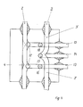
- the branches 6, 7, 8, like the branches 9, 10 and 11, are arranged offset in the direction of the axes of the conductors, so that only a single derivative can be represented in the sectional view. 2, the conductors 2, 3 and 4 are also installed in a metal encapsulation 1. It can be seen here how the individual conductors of the three-pole conductor arrangement 2, 3 and 4 each have two conductor sections, namely sections 2 ⁇ and 2 ⁇ ; 3 ⁇ and 3 ⁇ and 4 ⁇ and 4 ⁇ are joined together.
- the branches are guided in such a way that they either cut the imaginary connecting line between the conductors 3 and 4 as a bisector at right angles or by doing this with the imaginary connecting line between the conductors 2 and 4. It is easy to see that there is still space between conductors 2 and 3 for branching out if a third branching system is needed.
- connection points 12 for conductor sections e.g. B. 3 ⁇ and 3 ⁇ or for the connection of branches between the intersection of the perpendicular and the Axis of the conductor in the non-curved area.
- the branches 13 and 18 intersect imaginary connecting lines between the conductor axes as bisectors at right angles, while the branches 14, 15, 16, 17 intersect these connecting lines off-center and not at right angles.
- This arrangement has high voltage technology preference over the arrangement of FIGS. 1 and 2, because the, the homogeneity of the electric field disturbing components such. B.
- the connecting elements of the conductors at the connection points 12 assume a greater distance from the system parts with different potential and at the same time are relieved of the field of the own conductor.
- This arrangement can also be easily modified for the implementation of a third system.
- the exemplary embodiments are limited to the arrangement of the current conductors on the corners of an equilateral triangle.
- the invention is also applicable to other configurations. It may be advantageous to provide the conductors on the corners of an isosceles triangle and to dimension the length of the third leg greater than the two legs of equal length. In the area of this leg, such system parts can then be used as branches which, due to their shape, bring about a greater inhomogeneity of the field.
Landscapes
- Engineering & Computer Science (AREA)
- Power Engineering (AREA)
- Chemical & Material Sciences (AREA)
- Oil, Petroleum & Natural Gas (AREA)
- Gas-Insulated Switchgears (AREA)
- Installation Of Bus-Bars (AREA)
Applications Claiming Priority (2)
| Application Number | Priority Date | Filing Date | Title |
|---|---|---|---|
| DD28405285A DD244446A1 (de) | 1985-12-10 | 1985-12-10 | Dreipolige stromleiteranordnung mit abzweigstellen |
| DD284052 | 1985-12-10 |
Publications (2)
| Publication Number | Publication Date |
|---|---|
| EP0228504A2 true EP0228504A2 (fr) | 1987-07-15 |
| EP0228504A3 EP0228504A3 (fr) | 1988-11-30 |
Family
ID=5574060
Family Applications (1)
| Application Number | Title | Priority Date | Filing Date |
|---|---|---|---|
| EP86111472A Withdrawn EP0228504A3 (fr) | 1985-12-10 | 1986-08-19 | Disposition de conducteurs triphasés avec prises de dérivation |
Country Status (2)
| Country | Link |
|---|---|
| EP (1) | EP0228504A3 (fr) |
| DD (1) | DD244446A1 (fr) |
Cited By (1)
| Publication number | Priority date | Publication date | Assignee | Title |
|---|---|---|---|---|
| WO2001067573A1 (fr) * | 2000-03-07 | 2001-09-13 | Siemens Aktiengesellschaft | Installation de commutation haute tension triphasee comportant des modules encapsules monophases |
Family Cites Families (2)
| Publication number | Priority date | Publication date | Assignee | Title |
|---|---|---|---|---|
| FR1345792A (fr) * | 1961-11-20 | 1963-12-13 | Bbc Brown Boveri & Cie | Système de barres omnibus blindées sous tube à isolation par gaz comprimé |
| DE1994004U (de) * | 1968-07-19 | 1968-09-19 | Bbc Brown Boveri & Cie | Endstueck fuer druckgasisolierte sammelschienen. |
-
1985
- 1985-12-10 DD DD28405285A patent/DD244446A1/de not_active IP Right Cessation
-
1986
- 1986-08-19 EP EP86111472A patent/EP0228504A3/fr not_active Withdrawn
Cited By (1)
| Publication number | Priority date | Publication date | Assignee | Title |
|---|---|---|---|---|
| WO2001067573A1 (fr) * | 2000-03-07 | 2001-09-13 | Siemens Aktiengesellschaft | Installation de commutation haute tension triphasee comportant des modules encapsules monophases |
Also Published As
| Publication number | Publication date |
|---|---|
| DD244446A1 (de) | 1987-04-01 |
| EP0228504A3 (fr) | 1988-11-30 |
Similar Documents
| Publication | Publication Date | Title |
|---|---|---|
| DE3621268C2 (de) | Dreiphasig gekapselte, gasisolierte Schaltanlage | |
| DE3784920T2 (de) | Isoliergasschalter. | |
| DE69306037T2 (de) | Sammelschienen-Leitersystem für Hochspannungssysteme | |
| DE2639642A1 (de) | Anschlusskontaktanordnung mit klemmkontaktstuecken | |
| EP0472251B1 (fr) | Dispositif pour accouplement de barres omnibus | |
| EP0069693A2 (fr) | Container cylindrique pour une installation haute tension blindée tripolaire à isolation gazeuse | |
| EP0935325A1 (fr) | Installation de commutation à blindage mètallique et à isolation gazeuse | |
| DE3521945A1 (de) | Trennschalter fuer eine metallgekapselte, druckgasisolierte hochspannungsschaltanlage | |
| DE3020651A1 (de) | Gasisolierte schaltvorrichtung | |
| DE2360774C2 (de) | Dreiphasige, in einem Kapselungsrohr befindliche Stromleiteranordnung | |
| EP0012708B1 (fr) | Dispositif de commutation polyphasé à blindage métallique, isolé par du gaz sous pression, pour installations de commutation à haute tension | |
| DE3833718A1 (de) | Gasisolierte schaltvorrichtung | |
| DE19641391C1 (de) | Hochspannungsschaltanlage in Hybridbauweise | |
| DE1869455U (de) | Sammelschienenkanal fuer gekapselte elektrische verteilungen. | |
| DE19718639A1 (de) | Hochspannungsschaltanlage | |
| EP0228504A2 (fr) | Disposition de conducteurs triphasés avec prises de dérivation | |
| EP1262005B1 (fr) | Installation de commutation haute tension triphasee comportant des modules encapsules monophases | |
| DE3318229A1 (de) | Gehaeuse fuer hochspannungsschalter | |
| DE29806211U1 (de) | Kapselungsbaustein für eine Hochspannungsschaltanlage | |
| DE4414148A1 (de) | Stromschiene mit Querbrückung für Schaltanlagen-Reihenklemmen | |
| EP0829937A2 (fr) | Traversée de plein air pour récipient de tableau de distribution | |
| EP0075967A2 (fr) | Installation de commutation | |
| DE3137571C2 (fr) | ||
| DE2259058A1 (de) | Metallgekapselte, druckgasisolierte hochspannungsschaltanlage | |
| WO2007033947A1 (fr) | Ensemble barre collectrice pour une installation de distribution electrique a double face de commande |
Legal Events
| Date | Code | Title | Description |
|---|---|---|---|
| PUAI | Public reference made under article 153(3) epc to a published international application that has entered the european phase |
Free format text: ORIGINAL CODE: 0009012 |
|
| AK | Designated contracting states |
Kind code of ref document: A2 Designated state(s): AT CH DE FR LI NL SE |
|
| PUAL | Search report despatched |
Free format text: ORIGINAL CODE: 0009013 |
|
| AK | Designated contracting states |
Kind code of ref document: A3 Designated state(s): AT CH DE FR LI NL SE |
|
| 17P | Request for examination filed |
Effective date: 19890302 |
|
| 17Q | First examination report despatched |
Effective date: 19910422 |
|
| STAA | Information on the status of an ep patent application or granted ep patent |
Free format text: STATUS: THE APPLICATION IS DEEMED TO BE WITHDRAWN |
|
| 18D | Application deemed to be withdrawn |
Effective date: 19910903 |
|
| RIN1 | Information on inventor provided before grant (corrected) |
Inventor name: DIGMAYER, MICHAEL, DR.-ING. Inventor name: BOEHME, KLAUS, DR.-ING. Inventor name: SEIBT, GUENTER |