EP0228635B2 - Montre électronique - Google Patents
Montre électronique Download PDFInfo
- Publication number
- EP0228635B2 EP0228635B2 EP86117343A EP86117343A EP0228635B2 EP 0228635 B2 EP0228635 B2 EP 0228635B2 EP 86117343 A EP86117343 A EP 86117343A EP 86117343 A EP86117343 A EP 86117343A EP 0228635 B2 EP0228635 B2 EP 0228635B2
- Authority
- EP
- European Patent Office
- Prior art keywords
- solar cell
- cell arrangement
- electronic timepiece
- storage means
- display
- Prior art date
- Legal status (The legal status is an assumption and is not a legal conclusion. Google has not performed a legal analysis and makes no representation as to the accuracy of the status listed.)
- Expired - Lifetime
Links
Images

Classifications
-
- G—PHYSICS
- G04—HOROLOGY
- G04C—ELECTROMECHANICAL CLOCKS OR WATCHES
- G04C10/00—Arrangements of electric power supplies in time-pieces
- G04C10/02—Arrangements of electric power supplies in time-pieces the power supply being a radioactive or photovoltaic source
Definitions
- the invention relates to an electronic watch with a solar cell arrangement and a memory for the electrical energy supplied by the solar cell arrangement, the solar cell arrangement being connected to the memory via a device which prevents a backflow of current from the memory, and with a clock circuit connected to the memory and one of This driven display device and it further relates to an electronic watch with a clock circuit connected to a non-rechargeable battery and with a display device.
- Electronic clocks with a quartz oscillator belong to the prior art and are known, for example, from DE 21 46 776 C2.
- the power requirements of the electronic circuit and the displays have been continuously reduced in recent years.
- Such clocks are usually supplied with energy with the aid of primary batteries.
- Wristwatches that include a rechargeable battery and solar cells for charging are also known.
- Electronic watches with low-voltage capacitors with high capacitance have also recently come onto the market. The capacitors of such watches are charged with solar cells in the dial and guarantee a power reserve of 50 hours. However, this turns out to be too little for the winter season in the Federal Republic of Germany and in geographically similar countries.
- a watch is known from DE 33 37 407 A1, the display device of which is at least partially switched off by a photoresistor when the ambient brightness is insufficient, so that the overall power reserve of the watch is increased.
- the invention has for its object to provide an electronic watch of the type mentioned, which is characterized by a very high power reserve.
- the fact that the power supply is separated from the watch electronics and the display results in substantial energy savings and thus a higher power reserve.
- the display device which has the greatest energy requirement, in particular in the case of larger clocks, is operated directly via the solar cells of the solar cell arrangement without intermediate storage. This ensures that the display device is only in operation when the lighting is also sufficient for reading it.
- the clock circuit is operated with an energy store, either a battery or a capacitor, which ensures that the time function is retained.
- a mechanical pointer mechanism can also be used.
- a stepper motor is provided which is controlled in such a way that, after it has come to a standstill overnight, it brings the pointers of the pointer mechanism into the correct position when illuminated.
- the watch can also be equipped with an electronic calendar.
- the solar cell arrangement is used exclusively for feeding the display device and not for recharging the battery.
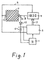
- the electronic watch shown in FIG. 1 has a quartz oscillator 1, which serves as a frequency reference for a watch circuit 2, by means of which the time keeping function of the electronic watch is ensured.
- the clock circuit 2 are assigned actuation switches, not shown in the drawing, which allow the clock circuit 2 to be set to a specific time, a specific date, a specific day of the week, a wake-up time or the like.
- actuation switches not shown in the drawing, which allow the clock circuit 2 to be set to a specific time, a specific date, a specific day of the week, a wake-up time or the like.
- components for stopwatch functions that may be present and acoustic displays for a time and / or alarm times are also not shown. It is self-evident to the person skilled in the art that the clock circuit 2 can be equipped with such additional circuits or functions.
- the clock circuit 2 is connected via a line 3 to a display device, which in the embodiment shown in FIG. 1 is a liquid crystal display 4 and in the embodiment of the invention shown in FIG. 2 is a mechanical pointer mechanism 5 with hands 10 and 11.
- a stepping motor with control electronics is assigned to the mechanical pointer mechanism 5 shown schematically in FIG. 2.
- the quartz oscillator 1 and the clock circuit 2 are supplied with electrical energy via an electrical memory 6.
- the electrical storage 6 is preferably a rechargeable battery or a low-voltage capacitor with a high capacity.
- a solar cell arrangement 7 shown in FIGS. 1 and 2 is connected via lines 8 and 9 to the liquid crystal display 4 or the mechanical pointer mechanism 5 in order to supply the liquid crystal display 4 or the pointer mechanism 5 with electrical energy.
- the liquid crystal display 4 or the pointer mechanism 5 is operated directly via the solar cell arrangement 7 without interposing the electrical memory 6. Since the display device has a greater energy requirement, in particular in the case of larger clocks, the power supply for the clock electronics and the display achieve substantial energy savings because the display in the form of the liquid crystal display 4 or the mechanical pointer mechanism 5 is only in operation when the lighting is also sufficient for reading.
- the clock circuit 2 is operated with the aid of the electrical memory 6, which can either be a battery or a capacitor, ensuring that the time function of the clock circuit 2 is retained.
- a diode 12 is provided in the exemplary embodiments shown in FIGS. 1 and 2.
- the diode 12 is connected with its anode to the line 8 and with its cathode to the positive pole of the electrical store 6, in particular an accumulator. This polarity ensures that for charging the memory 6 electrons from the negative pole 13 of the solar cell arrangement 7 can reach the negative pole of the electrical memory 6 and from the positive pole of the electrical memory 6 via the diode 12 to the positive pole 14 of the solar cell 7.
- the electrical store 6 is charged or recharged.
- the store 6 is discharged via the diode 12
- the diode 12 thus has the effect that the electrical memory 6 charged by the solar cell arrangement 7 supplies only the electronics, that is to say in particular the quartz oscillator 1 and the clock circuit 2, and that the display device, in particular the liquid crystal display 4 or the mechanical pointer mechanism 5 with a stepping motor, without Memory is fed directly from the solar cell arrangement 7.
- a non-rechargeable battery is used as the energy source instead of an electrical store 6, for example in the form of a rechargeable battery.
- the solar cell arrangement 7 is used in such an electronic watch exclusively for feeding the display device, in particular the liquid crystal display 4 or the mechanical pointer mechanism 5 and not for loading the memory 6. Therefore, in the last-mentioned exemplary embodiment there is no connection between the line 8 and the non-rechargeable battery is provided so that the diode 12 is omitted.
Landscapes
- Engineering & Computer Science (AREA)
- Power Engineering (AREA)
- Physics & Mathematics (AREA)
- General Physics & Mathematics (AREA)
- Electromechanical Clocks (AREA)
- Organic Low-Molecular-Weight Compounds And Preparation Thereof (AREA)
- Polysaccharides And Polysaccharide Derivatives (AREA)
- Mechanical Treatment Of Semiconductor (AREA)
Claims (9)
- Montre électronique, avec un dispositif à piles solaires, (7) et un accumulateur (6) pour l'énergie électrique fournie par le dispositif à piles solaires (7), le dispositif à piles solaires (7) étant relié à l'accumulateur (6) par l'intermédiaire d'un dispositif (12) empêchant tout retour de courant électrique depuis l'accumulateur (6), et avec un circuit de commande, raccordé à l'accumulateur (6), ainsi qu'un dispositif d'affichage (4, 5) commandé par celui-ci, caractérisée en ce que le dispositif d'affichage (4, 5) est directement raccordé au dispositif à piles solaires (7) pour assurer une alimentation électrique directe.
- Montre électronique selon la revendication 1, caractérisée en ce que le dispositif est une diode polarisée (12), passante dans le sens du courant de charge.
- Montre électronique selon la revendication 1 ou la revendication 2, caractérisée en ce que l'accumulateur (6) est une batterie rechargeable.
- Montre électronique selon la revendication 1 ou la revendication 2, caractérisée en ce que l'accumulateur (6) est un condensateur.
- Montre électronique selon l'une des revendications 1 à 4, caractérisée en ce que le dispositif d'affichage est un affichage à cristaux liquides (4).
- Montre électronique selon l'une des revendications 1 à 5, caractérisée en ce que le dispositif d'affichage est un mécanisme à aiguilles mécanique (5) qui est susceptible d'être mis en mouvement en cas de mise en oeuvre d'un éclairement orienté dans la position correcte, associée à l'heure de la montre.
- Montre électronique selon la revendication 6, caractérisée en ce que le mécanisme à aiguilles (10, 11) est entraîné par un moteur pas-à-pas.
- Montre électronique selon l'une des revendications précédentes, caractérisée en ce que d'autres indications, telles que la date, l'année et d'autres informations calendaires sont susceptibles d'être affichées, en plus de l'heure.
- Montre électronique avec un circuit de commande, raccordé à une batterie non-rechargeable, ainsi qu'avec un dispositif indicateur, caractérisée en ce que le dispositif indicateur (4, 5) est raccordé à un dispositif à piles solaires (7).
Priority Applications (1)
| Application Number | Priority Date | Filing Date | Title |
|---|---|---|---|
| AT86117343T ATE65334T1 (de) | 1986-01-10 | 1986-12-12 | Elektronische uhr. |
Applications Claiming Priority (2)
| Application Number | Priority Date | Filing Date | Title |
|---|---|---|---|
| DE3600515A DE3600515C1 (de) | 1986-01-10 | 1986-01-10 | Elektronische Uhr |
| DE3600515 | 1986-01-10 |
Publications (4)
| Publication Number | Publication Date |
|---|---|
| EP0228635A2 EP0228635A2 (fr) | 1987-07-15 |
| EP0228635A3 EP0228635A3 (en) | 1989-10-25 |
| EP0228635B1 EP0228635B1 (fr) | 1991-07-17 |
| EP0228635B2 true EP0228635B2 (fr) | 1995-10-18 |
Family
ID=6291622
Family Applications (1)
| Application Number | Title | Priority Date | Filing Date |
|---|---|---|---|
| EP86117343A Expired - Lifetime EP0228635B2 (fr) | 1986-01-10 | 1986-12-12 | Montre électronique |
Country Status (5)
| Country | Link |
|---|---|
| US (1) | US4763310A (fr) |
| EP (1) | EP0228635B2 (fr) |
| JP (1) | JPS62203085A (fr) |
| AT (1) | ATE65334T1 (fr) |
| DE (2) | DE3600515C1 (fr) |
Families Citing this family (12)
| Publication number | Priority date | Publication date | Assignee | Title |
|---|---|---|---|---|
| DE3707728A1 (de) * | 1987-03-11 | 1988-09-22 | Junghans Uhren Gmbh | Autonome funkuhr |
| KR910008218B1 (ko) * | 1989-11-30 | 1991-10-12 | 삼성전자 주식회사 | 비디오 프린터의 칼라 기록장치 |
| DE4314003A1 (de) * | 1993-04-26 | 1994-10-27 | Schwerdtle & Schantz Gmbh | Zeitkontrollvorrichtung |
| GB2343540A (en) * | 1998-11-06 | 2000-05-10 | Tacktick Ltd | Solar powered display |
| US6288979B1 (en) * | 2000-04-06 | 2001-09-11 | Moneray International Ltd. | Solar-driven eternity clock |
| TWI224722B (en) * | 2000-05-19 | 2004-12-01 | Asulab Sa | Electronic device for generating and displaying an item of information |
| US6838994B2 (en) * | 2001-10-26 | 2005-01-04 | Koninklijke Philips Electronics N.V. | Adaptive alarm system |
| US7615962B1 (en) * | 2005-03-04 | 2009-11-10 | World Factory, Inc. | Solar-powered thermometer and clock |
| JP2013152140A (ja) * | 2012-01-25 | 2013-08-08 | Seiko Instruments Inc | 電子時計 |
| JP2013156159A (ja) * | 2012-01-30 | 2013-08-15 | Seiko Instruments Inc | 電子時計 |
| US20140159637A1 (en) * | 2012-08-19 | 2014-06-12 | EnergyBionics, LLC | Portable energy harvesting, storing, and charging device |
| US9501040B2 (en) * | 2014-10-01 | 2016-11-22 | William J. McNulty, Jr. | Appliance or light timer including rechargeable back-up battery and external charger |
Family Cites Families (15)
| Publication number | Priority date | Publication date | Assignee | Title |
|---|---|---|---|---|
| CH373701A (de) * | 1961-02-06 | 1964-01-15 | Heno Watch S A | Lichtelektrisch betriebene Uhr |
| DE1782185A1 (de) * | 1968-07-29 | 1971-07-29 | Kemper Kate | Vorrichtung zum Wirken von Teigstuecken |
| JPS569674B1 (fr) * | 1970-09-18 | 1981-03-03 | ||
| US3928960A (en) * | 1973-02-06 | 1975-12-30 | Time Computer | Combination wristwatch and calculator |
| GB1481024A (en) * | 1974-07-15 | 1977-07-27 | Suisse Horlogerie | Battery powered electronic timepiece with voltage regulation |
| CH1181974A4 (fr) * | 1974-08-30 | 1977-06-15 | ||
| JPS51121365A (en) * | 1975-04-17 | 1976-10-23 | Seiko Epson Corp | Electric clock |
| US4015420A (en) * | 1976-05-03 | 1977-04-05 | Hughes Aircraft Company | Battery select circuitry and level translator for a digital watch |
| JPS5428176A (en) * | 1977-08-04 | 1979-03-02 | Seiko Instr & Electronics Ltd | Electronic watch |
| US4234947A (en) * | 1977-12-20 | 1980-11-18 | Citizen Watch Co., Ltd. | Solar battery powered timepiece |
| DE2918064A1 (de) * | 1978-05-08 | 1979-11-22 | Ebauches Sa | Vorrichtung zum laden eines akkumulators durch eine quelle elektrischer energie, insbesondere fuer eine elektronische uhr |
| DE3115682A1 (de) * | 1981-04-18 | 1982-11-04 | Varta Batterie Ag, 3000 Hannover | Batteriebetriebenes elektronisches geraet mit sicherung der spannungsversorgung fuer teilfunktionen |
| DE3337407A1 (de) * | 1983-10-14 | 1985-04-25 | Diehl GmbH & Co, 8500 Nürnberg | Messeinrichtung mit einer passiven anzeigevorrichtung |
| JPH0792506B2 (ja) * | 1984-11-21 | 1995-10-09 | セイコーエプソン株式会社 | 電子時計 |
| CH665081GA3 (fr) * | 1985-10-11 | 1988-04-29 |
-
1986
- 1986-01-10 DE DE3600515A patent/DE3600515C1/de not_active Expired - Fee Related
- 1986-12-12 AT AT86117343T patent/ATE65334T1/de not_active IP Right Cessation
- 1986-12-12 EP EP86117343A patent/EP0228635B2/fr not_active Expired - Lifetime
- 1986-12-12 DE DE8686117343T patent/DE3680310D1/de not_active Expired - Lifetime
-
1987
- 1987-01-05 US US07/000,399 patent/US4763310A/en not_active Expired - Fee Related
- 1987-01-07 JP JP62000640A patent/JPS62203085A/ja active Pending
Also Published As
| Publication number | Publication date |
|---|---|
| DE3600515C1 (de) | 1993-05-13 |
| EP0228635A3 (en) | 1989-10-25 |
| ATE65334T1 (de) | 1991-08-15 |
| EP0228635A2 (fr) | 1987-07-15 |
| US4763310A (en) | 1988-08-09 |
| JPS62203085A (ja) | 1987-09-07 |
| EP0228635B1 (fr) | 1991-07-17 |
| DE3680310D1 (de) | 1991-08-22 |
Similar Documents
| Publication | Publication Date | Title |
|---|---|---|
| EP0228635B2 (fr) | Montre électronique | |
| DE2513451A1 (de) | Elektronische uhr-rechner-einheit | |
| DE2122683A1 (de) | Uhr, deren Anzeigeeinrichtung mindestens eine Flüssigkristall-Zelle aufweist | |
| DE19780948B4 (de) | Kombinierte elektronische Uhr | |
| DE2821619B2 (de) | Elektronische Uhr mit Analoganzeige-Zeigerwerk und Flüssigkristall-Anzeigeeinheit | |
| DE3524290C2 (fr) | ||
| DE2646715B2 (de) | Am Handgelenk zu tragendes Instrument | |
| DE60031080T2 (de) | Zeitgebervorrichtung und Verfahren um diese zu kontrollieren | |
| DE60036591T2 (de) | Elektronische Uhr | |
| DE2452687A1 (de) | Schaltvorrichtung fuer eine elektronische uhr mit elektrooptischer anzeige | |
| DE2311508A1 (de) | Elektrooptische anzeige fuer elektronische uhren | |
| DE2618863C3 (de) | Elektronische Kleinuhr mit einer digitalen optischen Anzeigeeinrichtung | |
| DE2206102A1 (de) | Armbanduhr od. dgl. mit einem Schwingkristall als Zeitnormal | |
| DE3511009A1 (de) | Elektronische uhr mit analoganzeige | |
| EP0285838B1 (fr) | Horloge autonome radiopilotée | |
| CH524973A (de) | Verfahren zum Einführen und Aufziehen von Reissverschlussschiebern auf fortlaufende, gekuppelte Reissverschlussstreifen | |
| DE3903706A1 (de) | Uhr mit einem elektronischen uhrenbaustein | |
| DE2442394B2 (de) | Vollelektronische uhr | |
| DE69827362T2 (de) | Uhr mit detektions- und sparvorrichtungen im falle von nicht ausreichender energieversorgung | |
| DE3115682A1 (de) | Batteriebetriebenes elektronisches geraet mit sicherung der spannungsversorgung fuer teilfunktionen | |
| DE1673798A1 (de) | Elektrischer Zeitmesser | |
| CH671485A5 (en) | Power supply circuitry combining solar cell and sec. cell battery - charges lithium cells with capacitor for short duration back-up to overcome recharge delay after long dark periods | |
| DE2734721A1 (de) | Batteriebetriebene elektronische uhr | |
| DE69001343T2 (de) | Elektronische Zeitmessvorrichtung. | |
| DE1673798C (de) | Elektrischer Zeitmesser mit einem durch eine Solar- oder Photozelle aufladbaren Akkumulator |
Legal Events
| Date | Code | Title | Description |
|---|---|---|---|
| PUAI | Public reference made under article 153(3) epc to a published international application that has entered the european phase |
Free format text: ORIGINAL CODE: 0009012 |
|
| AK | Designated contracting states |
Kind code of ref document: A2 Designated state(s): AT BE CH DE ES FR GB GR IT LI NL SE |
|
| PUAL | Search report despatched |
Free format text: ORIGINAL CODE: 0009013 |
|
| AK | Designated contracting states |
Kind code of ref document: A3 Designated state(s): AT BE CH DE ES FR GB GR IT LI NL SE |
|
| 17P | Request for examination filed |
Effective date: 19890928 |
|
| 17Q | First examination report despatched |
Effective date: 19901001 |
|
| GRAA | (expected) grant |
Free format text: ORIGINAL CODE: 0009210 |
|
| AK | Designated contracting states |
Kind code of ref document: B1 Designated state(s): AT BE CH DE ES FR GB GR IT LI NL SE |
|
| PG25 | Lapsed in a contracting state [announced via postgrant information from national office to epo] |
Ref country code: GR Free format text: LAPSE BECAUSE OF FAILURE TO SUBMIT A TRANSLATION OF THE DESCRIPTION OR TO PAY THE FEE WITHIN THE PRESCRIBED TIME-LIMIT Effective date: 19910717 Ref country code: SE Effective date: 19910717 Ref country code: BE Effective date: 19910717 |
|
| REF | Corresponds to: |
Ref document number: 65334 Country of ref document: AT Date of ref document: 19910815 Kind code of ref document: T |
|
| ET | Fr: translation filed | ||
| REF | Corresponds to: |
Ref document number: 3680310 Country of ref document: DE Date of ref document: 19910822 |
|
| GBT | Gb: translation of ep patent filed (gb section 77(6)(a)/1977) | ||
| ITF | It: translation for a ep patent filed | ||
| PG25 | Lapsed in a contracting state [announced via postgrant information from national office to epo] |
Ref country code: AT Effective date: 19911231 |
|
| PLBI | Opposition filed |
Free format text: ORIGINAL CODE: 0009260 |
|
| 26 | Opposition filed |
Opponent name: DIEHL GMBH & CO. Effective date: 19920415 |
|
| NLR1 | Nl: opposition has been filed with the epo |
Opponent name: DIEHL GMBH & CO. |
|
| PUAH | Patent maintained in amended form |
Free format text: ORIGINAL CODE: 0009272 |
|
| STAA | Information on the status of an ep patent application or granted ep patent |
Free format text: STATUS: PATENT MAINTAINED AS AMENDED |
|
| 27A | Patent maintained in amended form |
Effective date: 19951018 |
|
| AK | Designated contracting states |
Kind code of ref document: B2 Designated state(s): AT BE CH DE ES FR GB GR IT LI NL SE |
|
| GBTA | Gb: translation of amended ep patent filed (gb section 77(6)(b)/1977) |
Effective date: 19951018 |
|
| REG | Reference to a national code |
Ref country code: CH Ref legal event code: AEN Free format text: AUFRECHTERHALTUNG DES PATENTES IN GEAENDERTER FORM |
|
| ET3 | Fr: translation filed ** decision concerning opposition | ||
| NLR2 | Nl: decision of opposition | ||
| NLR3 | Nl: receipt of modified translations in the netherlands language after an opposition procedure | ||
| ITF | It: translation for a ep patent filed | ||
| PG25 | Lapsed in a contracting state [announced via postgrant information from national office to epo] |
Ref country code: ES Free format text: LAPSE BECAUSE OF FAILURE TO SUBMIT A TRANSLATION OF THE DESCRIPTION OR TO PAY THE FEE WITHIN THE PRESCRIBED TIME-LIMIT Effective date: 19960129 |
|
| PGFP | Annual fee paid to national office [announced via postgrant information from national office to epo] |
Ref country code: GB Payment date: 19961129 Year of fee payment: 11 |
|
| PGFP | Annual fee paid to national office [announced via postgrant information from national office to epo] |
Ref country code: DE Payment date: 19961210 Year of fee payment: 11 |
|
| PGFP | Annual fee paid to national office [announced via postgrant information from national office to epo] |
Ref country code: FR Payment date: 19961217 Year of fee payment: 11 |
|
| PGFP | Annual fee paid to national office [announced via postgrant information from national office to epo] |
Ref country code: CH Payment date: 19961220 Year of fee payment: 11 |
|
| PGFP | Annual fee paid to national office [announced via postgrant information from national office to epo] |
Ref country code: NL Payment date: 19961223 Year of fee payment: 11 |
|
| PG25 | Lapsed in a contracting state [announced via postgrant information from national office to epo] |
Ref country code: GB Free format text: LAPSE BECAUSE OF NON-PAYMENT OF DUE FEES Effective date: 19971212 |
|
| PG25 | Lapsed in a contracting state [announced via postgrant information from national office to epo] |
Ref country code: LI Free format text: LAPSE BECAUSE OF NON-PAYMENT OF DUE FEES Effective date: 19971231 Ref country code: CH Free format text: LAPSE BECAUSE OF NON-PAYMENT OF DUE FEES Effective date: 19971231 Ref country code: FR Free format text: THE PATENT HAS BEEN ANNULLED BY A DECISION OF A NATIONAL AUTHORITY Effective date: 19971231 |
|
| PG25 | Lapsed in a contracting state [announced via postgrant information from national office to epo] |
Ref country code: NL Free format text: LAPSE BECAUSE OF NON-PAYMENT OF DUE FEES Effective date: 19980701 |
|
| GBPC | Gb: european patent ceased through non-payment of renewal fee |
Effective date: 19971212 |
|
| REG | Reference to a national code |
Ref country code: CH Ref legal event code: PL |
|
| NLV4 | Nl: lapsed or anulled due to non-payment of the annual fee |
Effective date: 19980701 |
|
| PG25 | Lapsed in a contracting state [announced via postgrant information from national office to epo] |
Ref country code: DE Free format text: LAPSE BECAUSE OF NON-PAYMENT OF DUE FEES Effective date: 19980901 |
|
| REG | Reference to a national code |
Ref country code: FR Ref legal event code: ST |
|
| PG25 | Lapsed in a contracting state [announced via postgrant information from national office to epo] |
Ref country code: IT Free format text: LAPSE BECAUSE OF NON-PAYMENT OF DUE FEES;WARNING: LAPSES OF ITALIAN PATENTS WITH EFFECTIVE DATE BEFORE 2007 MAY HAVE OCCURRED AT ANY TIME BEFORE 2007. THE CORRECT EFFECTIVE DATE MAY BE DIFFERENT FROM THE ONE RECORDED. Effective date: 20051212 |
|
| PG25 | Lapsed in a contracting state [announced via postgrant information from national office to epo] |
Ref country code: ES Free format text: LAPSE BECAUSE OF FAILURE TO SUBMIT A TRANSLATION OF THE DESCRIPTION OR TO PAY THE FEE WITHIN THE PRESCRIBED TIME-LIMIT Effective date: 19911231 |