EP0228723A2 - Bloc modulaire de connexion à bornes à déplacement d'isolant - Google Patents
Bloc modulaire de connexion à bornes à déplacement d'isolant Download PDFInfo
- Publication number
- EP0228723A2 EP0228723A2 EP86201979A EP86201979A EP0228723A2 EP 0228723 A2 EP0228723 A2 EP 0228723A2 EP 86201979 A EP86201979 A EP 86201979A EP 86201979 A EP86201979 A EP 86201979A EP 0228723 A2 EP0228723 A2 EP 0228723A2
- Authority
- EP
- European Patent Office
- Prior art keywords
- housing
- terminal
- terminal body
- wire
- block assembly
- Prior art date
- Legal status (The legal status is an assumption and is not a legal conclusion. Google has not performed a legal analysis and makes no representation as to the accuracy of the status listed.)
- Withdrawn
Links
- 238000009413 insulation Methods 0.000 claims abstract description 29
- 239000000463 material Substances 0.000 claims abstract description 11
- 239000007787 solid Substances 0.000 claims description 5
- 238000003780 insertion Methods 0.000 claims description 4
- 229920003023 plastic Polymers 0.000 claims description 4
- 239000004033 plastic Substances 0.000 claims description 4
- 238000004891 communication Methods 0.000 claims description 3
- 238000005520 cutting process Methods 0.000 claims description 3
- 238000000429 assembly Methods 0.000 abstract description 3
- 238000012986 modification Methods 0.000 abstract description 2
- 230000004048 modification Effects 0.000 abstract description 2
- 238000000034 method Methods 0.000 description 4
- 230000037431 insertion Effects 0.000 description 3
- 238000004519 manufacturing process Methods 0.000 description 3
- 230000000712 assembly Effects 0.000 description 2
- 238000013461 design Methods 0.000 description 2
- 238000003860 storage Methods 0.000 description 2
- 229910000881 Cu alloy Inorganic materials 0.000 description 1
- 239000004020 conductor Substances 0.000 description 1
- 239000000470 constituent Substances 0.000 description 1
- 238000010586 diagram Methods 0.000 description 1
- 238000009826 distribution Methods 0.000 description 1
- 230000000694 effects Effects 0.000 description 1
- 230000014759 maintenance of location Effects 0.000 description 1
- 238000005555 metalworking Methods 0.000 description 1
- 238000000465 moulding Methods 0.000 description 1
- 230000000717 retained effect Effects 0.000 description 1
- 229910000679 solder Inorganic materials 0.000 description 1
Images

Classifications
-
- H—ELECTRICITY
- H01—ELECTRIC ELEMENTS
- H01R—ELECTRICALLY-CONDUCTIVE CONNECTIONS; STRUCTURAL ASSOCIATIONS OF A PLURALITY OF MUTUALLY-INSULATED ELECTRICAL CONNECTING ELEMENTS; COUPLING DEVICES; CURRENT COLLECTORS
- H01R9/00—Structural associations of a plurality of mutually-insulated electrical connecting elements, e.g. terminal strips or terminal blocks; Terminals or binding posts mounted upon a base or in a case; Bases therefor
- H01R9/22—Bases, e.g. strip, block, panel
- H01R9/24—Terminal blocks
-
- H—ELECTRICITY
- H01—ELECTRIC ELEMENTS
- H01R—ELECTRICALLY-CONDUCTIVE CONNECTIONS; STRUCTURAL ASSOCIATIONS OF A PLURALITY OF MUTUALLY-INSULATED ELECTRICAL CONNECTING ELEMENTS; COUPLING DEVICES; CURRENT COLLECTORS
- H01R4/00—Electrically-conductive connections between two or more conductive members in direct contact, i.e. touching one another; Means for effecting or maintaining such contact; Electrically-conductive connections having two or more spaced connecting locations for conductors and using contact members penetrating insulation
- H01R4/24—Connections using contact members penetrating or cutting insulation or cable strands
- H01R4/2416—Connections using contact members penetrating or cutting insulation or cable strands the contact members having insulation-cutting edges, e.g. of tuning fork type
Definitions
- This invention is directed to the field of electrical interconnection components, and more particularly, to a novel modular IDC terminal block assembly.
- Terminal blocks commonly employed in the electronics industry for providing discrete and mass wire terminations to printed circuit (PC) or other interconnection boards, usually include several identical elements each constituted as an electrical interconnection member and a housing member.
- the interconnection members provide the intended wire termination function while the housings not only provide support for the terminated wires but also provide a structure for mounting the terminated wires to the PC or other interconnection board.
- the terminal bodies are typically configured either as pin-mateable or as PCB-insertable configurations, and are available in different lengths to meet the requirements of the particular application. Terminal bodies having the different mounting configurations in multiple lengths must then be severally stockpiled at a considerable inventory space requirement. Different, and costly, molds or other forming devices, moreover, must be dedicated for each of the several different-length terminal block assemblies, which then entails considerable preproduction costs.
- the interconnection members of the terminal blocks are typically of two types, the insulation displacing (IDC) type and the non-IDC type, the latter being generally disadvantageous insofar as the individual wires to be terminated must be prepped beforehand in a separate step in order to insure the requisite interconnection.
- the insulation displacing type interconnection members have resilient cutting blades that flex apart as they cut through the insulation surrounding the electrical wires to be terminated. But with multiple insertions and removals, a mechanical strain builds-up in the material of the fingers in such a way as to reduce their operative lifetime.
- IDC terminals are commonly provided in separate housings each dedicated to accepting a different gauge wire to be terminated.
- the corresponding gauge terminal block if it is unavailable, requires it to be specially ordered with a consequent undesirable delay.
- Separate stockpiles of the differently dimensioned terminals may be severally provided for the corresponding gauge sizes, and separate stockpiles of different terminal blocks for the correspondingly different gauges, may be severally provided to insure ready availability, but only at considerable storage space and inventory requirements.
- a fixturing assembly is usually used during the termination process such as specialized pliers for terminating wires into their associated insulation displacing terminals. If this tool is lost or otherwise unavailable, it would not be practicably possible to terminate the wires, since only the tool imparts the requisite mechanical advantage that overcomes the resistance of the wires being terminated.
- the tool to the extent that it must be specially provided, itself is costly to procure and manufacture and often is clumsy to handle and in use may result in damage to the terminal block.
- the novel terminal block assembly of the present invention overcomes these and other disadvantages and includes a longitudinal array of individual modules joined by severable webs to accomodate the termination needs of any one of a number of particular applications.
- Each module of the terminal block assembly is operable to terminate any one of several different gauge wires so that point of use termination flexibility is achieved and stockpile requirements are materially relaxed.
- a screwdriver, or pliers are useable to provide individual wire termination which eliminates any need for specially provided fixturing assemblies.
- the terminal block assembly of the present invention moreover has a simple design that is inexpensive to manufacture, is easy to assemble, use, and to handle, and that is operable in either a pin-mateable or a PCB-insertable configuration.
- the novel modules of the IDC terminal block assembly of the present invention include an insulation displacing terminal body that is slidably received in a housing member in such a way that the terminal body is recessed within the housing and is spaced along an elongated stress relieving slot defined by the housing member.
- the insulation displacing terminal body has solid spaced fingers, that are stationary, unflexing members, operative to slice through the insulation surrounding a wire to be terminated while deforming the material of the wire without any damage thereto, such as cutting or breakage.
- the stationary fingers of the insulation displacing terminal bodies prevent a cold-flow/creep condition, so that different gauge wires received therein are themselves deformed to a degree that depends on their relative thickness.
- the recessed position of the terminal body and the elongated stress relieving slot cooperate such that the wire terminations of the different gauge wires are each strain-relieved externally of the housing so that the mechanical and electrical interconnection is positive and secure notwithstanding the degree to which the wire is deformed.
- a cover member is releasably snapped into the top of the housing for pivoting motion between an open position, that allows access to the recessed insulation displacing terminal, and a closed position, which positively retains a terminated wire securely within the elongated stress receiving slot.
- a yoked cam is integrally formed with the cover in position to straddle either side of the insulation displacing terminal such that during pivoting motion between the open and closed positions the yoked cam bears down on both sides of the terminal and uniformly presses the wire to be terminated into the insulation displacing terminal body.
- the cammed cover is cooperative with the elongated slot and terminal body to both terminate the wires individually and to provide an additional measure of strain relief.
- the housing member of each of the modules of the terminal block assembly has surfaces defining an internal terminal guideway.
- First and second walls defining first and second apertures are provided in the housing for communicating the internal terminal guideway with different portions of the bottom surface of the housing.
- the guideway, and the first and second apertures make possible the use of the same, but differently configured insulation displacing terminal bodies to respectively provide PCB-insertability and plug-mateability.
- the terminal block assembly 10 includes a linear array of constitutive identical modules 12, preferably sixteen (16) in number, interconnected by corresponding ones of severable webs 14 integrally formed between adjacent modules 12 along the longitudinal axis of the terminal block assembly 10.
- any of the severable webs 14 are readily trimmable, by the manufacturer, or at the product distribution location, to provide that number of modules adapted for the termination requirements of a particular applications environment.
- the terminal block assembly 10 is preferably fabricated by well-known plastics molding techniques.
- each of the modules 16 include a housing member generally designated 18, a stress relieving cover member generally designated 20 pivotally mounted releasably to an edge of the housing member 18, and an insulation displacing terminal body generally designated 22 removably slidably received in opposing slots generally designated 25 centrally provided therefor in opposing reinforced sidewalls 26 of the housing member 18.
- the terminal body 22 has spaced fingers 27 defining an outside dimension therebetween, and the opposing walls 26 defined a maximum inside dimension between the slots 25.
- the maximum outside dimension and the maximum inside dimension are selected such that the opposing surfaces of the walls 26 always abut the fingers 27 for providing a guide during assembly of the terminal bodies 22, into the housing 18.
- the slots 25 are formed generally centrally along the length of the reinforced walls 26 such that the wire-to-IDC terminal interface is recessed within the body 18, which provides strain relief in a manner to be described.
- the spaced walls 26 defined therebetween an elongated stress receiving slot generally designated 28, and the IDC terminal body receiving slot 25 is in communication with the slot 28 at an interior position of the member 18.
- Opposing spaced-apart posts 30 are integrally provided with the housing member 18 to either side of the sidewalls of the member 18.
- the cover 20 is an elongated beam 32 having an integral end portion 34 on opposing sides of which bearing races 36 are provided. These races 36 have partial annular walls 38 defining a slot generally designated 40 therethrough located on that radius of the annular races 38 that is generally parallel with the direction of elongation of the beam 32.
- the cover 20 is slidably inserted into the housing 18 such that as the slots 40 pass through the posts 30 the cover 20 is releasably snapped thereonto and mounted thereon for pivoting motion relative to the housing member 18 between an open and a closed position.
- a yoked cam generally designated 42 is integrally formed with the beam 32 of the cover 20.
- the cam 42 includes first and second spaced lobes 44, 46 repectively positioned to straddle either side of the insulation displacing terminal 22 so as to bear against and urge both sides of a wire received in the contact body 22 to force it therethrough as the cover 20 pivots into its closed position.
- the motion of the wire through the stationary fingers 27 of the insulation displacing terminal body 20 acts to cut through the insulation surrounding the wire and to plastically deform the material of the wire itself to an extent that depends on the particular gauge of the wire being terminated.
- a resilient flange 47 is integrally formed with the cover 20 on the edge thereof remote from the edge at which the cover is pivotally mounted to the housing 18.
- the flange 47 cooperates with spaced confronting resilient abutments 48 integrally formed on the edge of the housing 18 remote from the edge thereof having the posts 30 to provide a latching action that releasably retains the cover 20 in its closed position.
- the dimensions of the flange 47 and flexible abutments 48 are selected to provide a frictional retaining force that is greater than the nominal upward force that is exerted thereagainst by compressed insulation of the terminated wire.
- any other suitable releasable latch can be employed without departing from the inventive concept.
- a push down tool receiving slot generally designated 50 is provided in the beam portion 32 of the cover 20.
- the push down tool receiving slot is cooperative with any suitable commonly available instrument, such as a screwdriver, to retain the tool against sliding motion so as to allow the downward mechanical force imparted thereby to pivot the cover into its closed position.
- Bevelled edges 52 are provided at the free ends of the fingers 27 of the terminal body 22 for guiding a wire to be terminated into a slot generally designated 54 formed thereinbetween.
- Bevelled blade portions 56 likewise having bevelled guide surfaces 58, are integrally formed within the slot 54.
- These blades preferably are fabricated of a plated copper alloy, and have sufficient strength imparting characteristics such as material thickness, the use of work-hardened materials, and the like, to provide such rigidity to the fingers as to prevent their flexing motion during termination.
- the fingers are operative to slice through insulation and plastically deform the conductor(s) of a wore moved downwardly therethrough by a well-known terminating action.
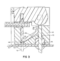
- FIG. 3 generally designated at 60 is a sectional view of a module of the terminal block assembly of the present invention as taken along the lines 3-3 of Figure 2.
- the housing 18 is formed with an integral generally V-shaped wall 62 (also viewable in Figure 2) that defines a terminal receiving guideway therein.
- Walls 64, 66 defining apertures generally designated 68, 70 are provided at spaced points in the bottom of the housing 18 that intercommunicate the internal terminal guideway defined by the generally V-shaped walls 62 with the external bottom surface of the housing 18.
- the guideway defined by the wall 62, and the apertures 68, 70 cooperate to provide either a plug-mateable or a printed circuit board insertable module configuration.
- the terminal body 22 is provided with an integral electrode tail 72.
- the tail 72 and the fingers 27 share a common axis of elongation such that the electrode tails 72 extend through the apertures 68 and beyond the lower surface of the housing as shown in Figure 2 and as shown dashed in Figure 3.
- the axially extending electrode tail 72 defines a pin that is readily mounted into a hole provided therefor in a printed circuit board 74 and retained therein as by solder 75 for establishing a good electrical connection.
- the electrode tails 72 of the terminal bodies 22 are pre-bent into a generally V-shaped configuration that matches the shape of the walls 62 as shown generally at 76.
- a pin 77 extending off a pin body header 78 that is mounted to the printed circuit board 74 is received through the aperture 70 and mechanically and electrically contacts the bent end 76 of the tail of the terminal body.
- the terminals for each configuration are, for example, stamped by well-known metal working techniques on a leadframe in unison, and can then be bent in a suitable press for the plug-mateable configuration or left in the un-formed condition for the PCB-insertable configuration.
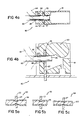
- FIGS. 4A and 4B generally designated respectively at 80 and 82 are top and side views illustrating both the point of wire-to-IDC terminal termination and the manner by which strain relief is accomplished.
- a wire 82 is shown terminated between the fingers 27 of the terminal body 22 received in the slot 28 provided therefor in the housing 18.
- the wire 82 longitudinally extends through the elongated slot 28, and the terminal body 22 is recessed within the housing 18 by a distance "D" from the insertion face of the member 18.
- wire 82 is flexed to the side as illustrated by dashed outline 84, and if it is flexed vertically as illustrated by dashed outline 85, flexing stresses produced thereby and as schematically illustrated by force arrows 86, 87 are terminated in the outer face of the housing member 18, and in such a way that the resulting strains are externally relieved remote from the recessed terminal body 22 leaving the termination substantially uneffected by the flexing stresses.
- the walls defining the recessed elongated slot 28, the stress-relieving cover 20 in its latched-down condition, and a shoulder 88 cooperate to effectively hold the wire 82 in a precise, movement-free spacial orientation. Any stressing forces acting through the wire, therefore, are terminated in the housing well-short of the wire-to-terminal interface and outside the housing, which makes possible the secure retention of the wire in the terminal even where the wire is deformed a considerable portion of its diameter. Multiple-gauge wires therewith are capable of being accepted in the same insulation displacing terminal body.
- FIG 5 generally designated at 90 in Figure 5A, at 92 in Figure 5B, and at 94 in Figure 5C are schematic views illustrating the state of termination of different gauge wires respectively.
- an exemplary 18 gauge insulated wire 96 is shown terminated in the fingers 27 of the terminal body 22 where the diameter of the 18 gauge wire is deformed approximately 46 percent.
- an exemplary 20 gauge insulated wire 98 is shown terminated therein in such a way that its diameter is deformed approximately 20 to 25 percent.
- an exemplary 22 gauge wire 100 is shown terminated with approximately 15-19 percent of its diameter deformed.
- the dimensions of the terminal body slots are preferably selected to be the median of the multiple gauge wires to be terminated therein.
- the present invention thus makes possible the provision of a terminal block assembly having any selected number of modules, each independently capable of accepting multiple gauge solid or stranded wires, where termination is accomplished readily in-the-field with commonly-available tools.
- the modules of the terminal block assembly have pivoting cover members having integral bearing surfaces that are cooperative with the insertion tool to retain unprepared wires in insulation displacing terminal bodies.
- the housing member of the modules includes a terminal guideway in communication with the bottom thereof through first and second apertures and the same but differently configured terminal bodies can be received in the guideways in such a way that the resulting terminal body configuration is either plug-mateable or PCB-insertable.
- the whole assembly minimizes inventory requirements, materially simplifies the assembly process, and is capable of low-cost fabrication while still providing highly-reliable and repeatable termination.
Landscapes
- Multi-Conductor Connections (AREA)
- Connections Arranged To Contact A Plurality Of Conductors (AREA)
- Coupling Device And Connection With Printed Circuit (AREA)
- Connections By Means Of Piercing Elements, Nuts, Or Screws (AREA)
Applications Claiming Priority (2)
| Application Number | Priority Date | Filing Date | Title |
|---|---|---|---|
| US79723185A | 1985-11-12 | 1985-11-12 | |
| US797231 | 1985-11-12 |
Publications (2)
| Publication Number | Publication Date |
|---|---|
| EP0228723A2 true EP0228723A2 (fr) | 1987-07-15 |
| EP0228723A3 EP0228723A3 (fr) | 1987-12-23 |
Family
ID=25170283
Family Applications (1)
| Application Number | Title | Priority Date | Filing Date |
|---|---|---|---|
| EP86201979A Withdrawn EP0228723A3 (fr) | 1985-11-12 | 1986-11-11 | Bloc modulaire de connexion à bornes à déplacement d'isolant |
Country Status (2)
| Country | Link |
|---|---|
| EP (1) | EP0228723A3 (fr) |
| JP (1) | JPS62117283A (fr) |
Cited By (7)
| Publication number | Priority date | Publication date | Assignee | Title |
|---|---|---|---|---|
| EP0310832A3 (en) * | 1987-09-25 | 1990-04-25 | Reichle + De-Massari Ag Elektro-Ingenieure | Multiple contact pin support for low-voltage installations |
| FR2661049A1 (fr) * | 1990-04-12 | 1991-10-18 | Pouyet Henri | Module de raccordement et de protection pour dispositifs de connexions de conducteurs electriques par autodenudage. |
| EP0643454A1 (fr) * | 1993-09-10 | 1995-03-15 | KRONE Aktiengesellschaft | Module de connexion |
| WO1998057399A1 (fr) * | 1997-06-12 | 1998-12-17 | Siemens Aktiengesellschaft | Dispositif pour deformer des enrobages de lignes electriques et procede pour deformer des enrobages de lignes electriques au moyen d'un tel dispositif |
| WO2009043470A3 (fr) * | 2007-10-04 | 2009-05-22 | Ccs Technology Inc | Réglette de répartiteur d'une installation de télécommunications |
| US7740509B2 (en) | 2005-05-10 | 2010-06-22 | Tyco Electronics Raychem Sa | Electrical wire connector |
| WO2014000920A1 (fr) * | 2012-06-27 | 2014-01-03 | Robert Bosch Gmbh | Élément de contact destiné à être connecté à une carte de circuits imprimés, système de contact et procédé |
Family Cites Families (7)
| Publication number | Priority date | Publication date | Assignee | Title |
|---|---|---|---|---|
| US3854114A (en) * | 1972-08-10 | 1974-12-10 | J Kloth | Notched plate clasp apparatus |
| US3820055A (en) * | 1972-11-14 | 1974-06-25 | Amp Inc | Multi-contact connector and contact terminal for flat cable |
| US4045112A (en) * | 1976-04-05 | 1977-08-30 | General Motors Corporation | Unitary insulator housing with secondary latch means and electrical connector utilizing same |
| US4163596A (en) * | 1978-01-27 | 1979-08-07 | Minnesota Mining And Manufacturing Company | Electrical connector |
| US4243286A (en) * | 1979-02-21 | 1981-01-06 | Methode Electronics, Inc. | Insulation displacement connector |
| DE3024307A1 (de) * | 1980-06-27 | 1982-01-21 | Siemens AG, 1000 Berlin und 8000 München | Kunststoffkoerper mit zumindest einem anschlusselement fuer elektrische leiter |
| ZA827821B (en) * | 1981-11-04 | 1984-06-27 | Racal Acoustics Ltd | Highway cable connector |
-
1986
- 1986-11-11 EP EP86201979A patent/EP0228723A3/fr not_active Withdrawn
- 1986-11-12 JP JP61269519A patent/JPS62117283A/ja active Pending
Cited By (9)
| Publication number | Priority date | Publication date | Assignee | Title |
|---|---|---|---|---|
| EP0310832A3 (en) * | 1987-09-25 | 1990-04-25 | Reichle + De-Massari Ag Elektro-Ingenieure | Multiple contact pin support for low-voltage installations |
| FR2661049A1 (fr) * | 1990-04-12 | 1991-10-18 | Pouyet Henri | Module de raccordement et de protection pour dispositifs de connexions de conducteurs electriques par autodenudage. |
| EP0643454A1 (fr) * | 1993-09-10 | 1995-03-15 | KRONE Aktiengesellschaft | Module de connexion |
| WO1998057399A1 (fr) * | 1997-06-12 | 1998-12-17 | Siemens Aktiengesellschaft | Dispositif pour deformer des enrobages de lignes electriques et procede pour deformer des enrobages de lignes electriques au moyen d'un tel dispositif |
| US7740509B2 (en) | 2005-05-10 | 2010-06-22 | Tyco Electronics Raychem Sa | Electrical wire connector |
| WO2009043470A3 (fr) * | 2007-10-04 | 2009-05-22 | Ccs Technology Inc | Réglette de répartiteur d'une installation de télécommunications |
| WO2014000920A1 (fr) * | 2012-06-27 | 2014-01-03 | Robert Bosch Gmbh | Élément de contact destiné à être connecté à une carte de circuits imprimés, système de contact et procédé |
| CN104412454A (zh) * | 2012-06-27 | 2015-03-11 | 罗伯特·博世有限公司 | 用于连接电路板的接触元件、接触系统以及方法 |
| US9484643B2 (en) | 2012-06-27 | 2016-11-01 | Robert Bosch Gmbh | Contact element for connecting to a circuit board, contact system and method |
Also Published As
| Publication number | Publication date |
|---|---|
| JPS62117283A (ja) | 1987-05-28 |
| EP0228723A3 (fr) | 1987-12-23 |
Similar Documents
| Publication | Publication Date | Title |
|---|---|---|
| US4159158A (en) | Displation connector having improved terminal supporting means | |
| US5382168A (en) | Stacking connector assembly of variable size | |
| EP0569893B1 (fr) | Connecteur électrique à profil bas | |
| US5577930A (en) | Electrical connector with improved conductor retention means | |
| US4964812A (en) | Wire termination block | |
| US7794267B2 (en) | Card edge connector with IDC wire termination | |
| EP0308448B1 (fr) | Connecteur cable-a-broche flexible plat a terminaison en masse | |
| US4191442A (en) | Electrical connector and method of fabricating a wire harness using the connector | |
| US4327956A (en) | Low insertion force dual beam pin terminal and connector | |
| EP0392193A2 (fr) | Connecteur pour câbles | |
| EP0043627A2 (fr) | Connecteur pour un câble plat à plusieurs conducteurs | |
| EP0097018B1 (fr) | Borne pour verrouillage à contact perçant l'isolation | |
| EP0404450A2 (fr) | Connecteur électrique aux fentes pour l'introduction de fils | |
| EP0305597A2 (fr) | Contacts fabriqués en bande | |
| US5358424A (en) | Electrical connector for high density ribbon cable | |
| US4508410A (en) | Electrical termination system and connector member | |
| EP0249330A2 (fr) | Terminal et connecteur à déplacement d'isolation | |
| US4370009A (en) | Slotted plate terminal renewable as spade terminal | |
| US5009618A (en) | Method and apparatus for making electrical connecting device | |
| EP0228723A2 (fr) | Bloc modulaire de connexion à bornes à déplacement d'isolant | |
| US5114362A (en) | High density electrical connector and method of making a high density electrical connector | |
| US7070442B2 (en) | Structure for press-connecting sheathed electric wire with terminal | |
| US4512620A (en) | Mass termination electrical connector | |
| EP0055876A2 (fr) | Connecteur à déplacement d'isolant pour des câbles discrets | |
| KR100710447B1 (ko) | 플러그 커넥터, 플러그 컨택트, 및 플러그 커넥터의조립방법 |
Legal Events
| Date | Code | Title | Description |
|---|---|---|---|
| PUAI | Public reference made under article 153(3) epc to a published international application that has entered the european phase |
Free format text: ORIGINAL CODE: 0009012 |
|
| AK | Designated contracting states |
Kind code of ref document: A2 Designated state(s): DE FR GB |
|
| PUAL | Search report despatched |
Free format text: ORIGINAL CODE: 0009013 |
|
| AK | Designated contracting states |
Kind code of ref document: A3 Designated state(s): DE FR GB |
|
| STAA | Information on the status of an ep patent application or granted ep patent |
Free format text: STATUS: THE APPLICATION IS DEEMED TO BE WITHDRAWN |
|
| 18D | Application deemed to be withdrawn |
Effective date: 19880624 |
|
| RIN1 | Information on inventor provided before grant (corrected) |
Inventor name: NAYLOR, HERBERT C. Inventor name: BAUSERMAN, GEORGE G. Inventor name: GEIB, LAWRENCE E. |