EP0228738A1 - Plattenspieler - Google Patents
Plattenspieler Download PDFInfo
- Publication number
- EP0228738A1 EP0228738A1 EP86202239A EP86202239A EP0228738A1 EP 0228738 A1 EP0228738 A1 EP 0228738A1 EP 86202239 A EP86202239 A EP 86202239A EP 86202239 A EP86202239 A EP 86202239A EP 0228738 A1 EP0228738 A1 EP 0228738A1
- Authority
- EP
- European Patent Office
- Prior art keywords
- turntables
- supporting member
- disc player
- disc
- motor
- Prior art date
- Legal status (The legal status is an assumption and is not a legal conclusion. Google has not performed a legal analysis and makes no representation as to the accuracy of the status listed.)
- Granted
Links
- 230000005540 biological transmission Effects 0.000 claims 1
- 238000010276 construction Methods 0.000 description 10
Images

Classifications
-
- G—PHYSICS
- G11—INFORMATION STORAGE
- G11B—INFORMATION STORAGE BASED ON RELATIVE MOVEMENT BETWEEN RECORD CARRIER AND TRANSDUCER
- G11B3/00—Recording by mechanical cutting, deforming or pressing, e.g. of grooves or pits; Reproducing by mechanical sensing; Record carriers therefor
- G11B3/60—Turntables for record carriers
-
- G—PHYSICS
- G11—INFORMATION STORAGE
- G11B—INFORMATION STORAGE BASED ON RELATIVE MOVEMENT BETWEEN RECORD CARRIER AND TRANSDUCER
- G11B19/00—Driving, starting, stopping record carriers not specifically of filamentary or web form, or of supports therefor; Control thereof; Control of operating function ; Driving both disc and head
- G11B19/20—Driving; Starting; Stopping; Control thereof
- G11B19/2009—Turntables, hubs and motors for disk drives; Mounting of motors in the drive
-
- G—PHYSICS
- G11—INFORMATION STORAGE
- G11B—INFORMATION STORAGE BASED ON RELATIVE MOVEMENT BETWEEN RECORD CARRIER AND TRANSDUCER
- G11B25/00—Apparatus characterised by the shape of record carrier employed but not specific to the method of recording or reproducing, e.g. dictating apparatus; Combinations of such apparatus
- G11B25/04—Apparatus characterised by the shape of record carrier employed but not specific to the method of recording or reproducing, e.g. dictating apparatus; Combinations of such apparatus using flat record carriers, e.g. disc, card
- G11B25/043—Apparatus characterised by the shape of record carrier employed but not specific to the method of recording or reproducing, e.g. dictating apparatus; Combinations of such apparatus using flat record carriers, e.g. disc, card using rotating discs
Definitions
- the invention relates to a disc player comprising two drivable turntables for supporting discs, the turntables being provided on a common supporting member which can be swung about a swing axis between a first position in which a disc supported by one turntable will be in a play position and a second position in which a disc supported by the other turntable will be in the play position.
- Such a disc player is known from British Patent Specification 2,137,797.
- various types of discs can be played using the same disc player, for example, discs having video information or discs having audio information, in which for each of the two types of disc a suitable turntable can be accommodated in a position suitable for playing.
- each turntable is connected to the outgoing shaft of an individual driving motor and the two driving motors are connected at a distance from each other to the common supporting member in such a manner that the axes of rotation of the motors enclose an angle with each other.
- the supporting member can be swung over a corresponding angle between two positions in which in one position the axis of rotation of one motor is vertical and in the other position the axis of rotation of the other motor is vertical.
- one motor may be used for driving the two turntables, which motor can be united with the supporting member and the turntables to form a compact unit which can be adjusted, for example, over 180° so that a simple and light-weight construction of the disc player can be achieved.
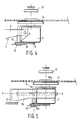
- a support 2 which comprises two arms 3 extending parallel to each other is connected to a housing 1 of a disc player shown diagrammatically only in Figure 1.
- a supporting member 4 is present which comprises a first plate-shaped part 5 an edge of which is adjoined by a plate-shaped part 6 which extends at right angles to the plate-shaped part 5.
- the connection between the two plate-shaped parts 5 and 6 is reinforced by means of two plate-shaped flanges 7 and 8 which extend at right angles to the sides of the plate-shaped part 6 and which also extend at right angles to the plate-shaped part 5.
- the supporting member 4 is coupled to the support 2 so as to be swingable by means of pins 9 and 10 which are in the elongation of each other and which are threaded through holes provided in the arms 3 and in the flanges 7 and 8.
- the motor 11 has a shaft 12 which projects beyond the housing of the motor 11 at each end.
- a pulley 13 is connected to the end of the shaft 12 which, viewed in Figure 1, is the top end.
- a turntable 14 known per se is connected for supporting a disc carrying video information, a so-called video disc.
- a sleeve 15 is connected to the plate-shaped part 6 of the support 4, in which sleeve a shaft 16 is journalled so as to be freely rotatable.
- the shaft 16 extends parallel to the shaft 12.
- a pulley 17 is connected which is coupled to the pulley 13 by means of a belt 18.
- a turntable 18 is connected above the pulley 17 to the shaft 16, which turntable 18 has a conventional construction for receiving a disc carrying audio information, for example a so-called compact disc.
- a disc 20 shown diagrammatically and present in Figure 1 on the turntable 18 will hence assume the same position with respect to components of the disc player which are important for playing the disc - for example, the pick-up member or the clamping member 21 with which the disc is clamped on the turntable - as a disc 20 which is supported by the turntable 14 if this has been moved to the position shown in Figure 4.
- the supporting member 4 may be connected to the support 2 in such a manner that the supporting member 4, shown in Figure 5, is movable with respect to the support 2 in a horizontal direction over a distance which is equal to the centre distance between the two shafts 12 and 16.
- the support 2 may comprise a long pin 9 a which is provided centrally between the arms 3 of the support 2 and extends parallel thereto.
- the supporting member 4 with the motor 11 is connected by means of a construction suitable for this purpose to the pin 9 a in such a manner that both a swinging movement and a sliding movement along the swing axis Y-Y are possible.
- Such a movement possibility may be omitted when a driving motor for the turntable is used which can rotate at two speeds.
- the two turntables can be assembled directly on the ends of the shaft 12 projecting from the motor and means may be provided which, when the supporting member 4 is swung through 180°, automatically also switch the motor 11 to a different speed.
- a motor which can rotate at two speeds and in which the two turntables are assembled directly on the ends of the shaft 12, may also be used in the arrangement shown in Figure 1 in which case the pins 9 and 10 may be provided in such a manner that the centre lines of said pins 9 and 10 intersect the centre line of the shaft 12.
- the structure of the conventional disc player for example as described in United States Patent Specification 4,218,065, can be substantially maintained since for accommodating the swingable motor with the two turntables, little more space is necessary than is required for accommodating a fixedly arranged motor with turntable in the conventional disc player so that, while maintaining all the possibilities and advantages of the conventional disc player, the disc player nevertheless can be used in a simple manner for different types of discs.
- the construction according to the invention is particularly suitable for performing a small tilt of the turntable in the operating condition in order to correct for the lopsided position of a disc on the turntable in question.
Landscapes
- Holding Or Fastening Of Disk On Rotational Shaft (AREA)
- Packaging For Recording Disks (AREA)
Applications Claiming Priority (2)
| Application Number | Priority Date | Filing Date | Title |
|---|---|---|---|
| NL8503522 | 1985-12-20 | ||
| NL8503522A NL8503522A (nl) | 1985-12-20 | 1985-12-20 | Platenspeler. |
Publications (2)
| Publication Number | Publication Date |
|---|---|
| EP0228738A1 true EP0228738A1 (de) | 1987-07-15 |
| EP0228738B1 EP0228738B1 (de) | 1990-04-11 |
Family
ID=19847046
Family Applications (1)
| Application Number | Title | Priority Date | Filing Date |
|---|---|---|---|
| EP86202239A Expired - Lifetime EP0228738B1 (de) | 1985-12-20 | 1986-12-11 | Plattenspieler |
Country Status (6)
| Country | Link |
|---|---|
| US (1) | US4783777A (de) |
| EP (1) | EP0228738B1 (de) |
| JP (1) | JPS62150555A (de) |
| KR (1) | KR870006510A (de) |
| DE (1) | DE3670393D1 (de) |
| NL (1) | NL8503522A (de) |
Cited By (1)
| Publication number | Priority date | Publication date | Assignee | Title |
|---|---|---|---|---|
| EP0275600A1 (de) * | 1986-12-24 | 1988-07-27 | Koninklijke Philips Electronics N.V. | Plattenspieler, geeignet zum Abtasten von Platten verschiedener Art |
Families Citing this family (4)
| Publication number | Priority date | Publication date | Assignee | Title |
|---|---|---|---|---|
| CA1322249C (en) * | 1988-08-30 | 1993-09-14 | Taizo Isshiki | Disc player |
| US5539712A (en) * | 1989-10-17 | 1996-07-23 | Nsm Aktiengesellschaft | Lifting and lowering device for a record playback unit in a record playing device |
| JP2749703B2 (ja) * | 1990-05-22 | 1998-05-13 | パイオニア株式会社 | ディスクプレーヤ |
| US20100158649A1 (en) * | 2008-12-23 | 2010-06-24 | Schwing Bioset, Inc. | Silo with reciprocating frame having composite blade |
Citations (5)
| Publication number | Priority date | Publication date | Assignee | Title |
|---|---|---|---|---|
| US4339778A (en) * | 1980-04-11 | 1982-07-13 | Atari, Inc. | Dual floppy disc machine |
| US4359762A (en) * | 1980-05-13 | 1982-11-16 | Stollorz Herbert R | Removable storage module and module |
| DE3303433A1 (de) * | 1982-02-02 | 1983-08-11 | Canon Denshi K.K., Chichibu, Saitama | Magnetplattenantriebsvorrichtung |
| GB2137797A (en) * | 1983-02-03 | 1984-10-10 | Pioneer Electronic Corp | Dual mode disc player |
| US4499514A (en) * | 1981-03-31 | 1985-02-12 | Olympus Optical Co., Ltd. | Disc drive apparatus |
Family Cites Families (5)
| Publication number | Priority date | Publication date | Assignee | Title |
|---|---|---|---|---|
| GB403353A (en) * | 1932-03-14 | 1933-12-21 | Gerardus Johannes Verburgh | Improvements in or relating to gramophones |
| US2837338A (en) * | 1954-03-23 | 1958-06-03 | Lloyd J Andres | Continuous multiple record player |
| US2944826A (en) * | 1957-10-07 | 1960-07-12 | Bonifacius G Van Essen | Record player |
| NL182032C (nl) * | 1978-06-05 | 1987-12-16 | Philips Nv | Inrichting voor het centreren, richten en vastklemmen van een roterende plaat. |
| JPS60106280U (ja) * | 1983-12-22 | 1985-07-19 | パイオニア株式会社 | デイスクプレ−ヤ |
-
1985
- 1985-12-20 NL NL8503522A patent/NL8503522A/nl not_active Application Discontinuation
-
1986
- 1986-12-11 DE DE8686202239T patent/DE3670393D1/de not_active Expired - Lifetime
- 1986-12-11 EP EP86202239A patent/EP0228738B1/de not_active Expired - Lifetime
- 1986-12-17 KR KR860010818A patent/KR870006510A/ko not_active Withdrawn
- 1986-12-17 JP JP61299008A patent/JPS62150555A/ja active Pending
- 1986-12-19 US US06/945,062 patent/US4783777A/en not_active Expired - Fee Related
Patent Citations (5)
| Publication number | Priority date | Publication date | Assignee | Title |
|---|---|---|---|---|
| US4339778A (en) * | 1980-04-11 | 1982-07-13 | Atari, Inc. | Dual floppy disc machine |
| US4359762A (en) * | 1980-05-13 | 1982-11-16 | Stollorz Herbert R | Removable storage module and module |
| US4499514A (en) * | 1981-03-31 | 1985-02-12 | Olympus Optical Co., Ltd. | Disc drive apparatus |
| DE3303433A1 (de) * | 1982-02-02 | 1983-08-11 | Canon Denshi K.K., Chichibu, Saitama | Magnetplattenantriebsvorrichtung |
| GB2137797A (en) * | 1983-02-03 | 1984-10-10 | Pioneer Electronic Corp | Dual mode disc player |
Non-Patent Citations (2)
| Title |
|---|
| PATENT ABSTRACTS OF JAPAN, vol. 7, no. 196, (P-219)[1341], 26th August 1983; & JP-A-58 094 171 (FUJI DENKI SEIZO K.K.) 04.06.1983 * |
| PATENT ABSTRACTS OF JAPAN, vol. 8, no. 10 (P-248)[1447], 18th January 1984; & JP-A-58 169 369 (KIYANON DENSHI K.K.) 05.10.1983 * |
Cited By (2)
| Publication number | Priority date | Publication date | Assignee | Title |
|---|---|---|---|---|
| EP0275600A1 (de) * | 1986-12-24 | 1988-07-27 | Koninklijke Philips Electronics N.V. | Plattenspieler, geeignet zum Abtasten von Platten verschiedener Art |
| US4833666A (en) * | 1986-12-24 | 1989-05-23 | U.S. Philips Corporation | Disc-record player suitable for scanning disc of different types |
Also Published As
| Publication number | Publication date |
|---|---|
| EP0228738B1 (de) | 1990-04-11 |
| KR870006510A (ko) | 1987-07-11 |
| JPS62150555A (ja) | 1987-07-04 |
| DE3670393D1 (de) | 1990-05-17 |
| NL8503522A (nl) | 1987-07-16 |
| US4783777A (en) | 1988-11-08 |
Similar Documents
| Publication | Publication Date | Title |
|---|---|---|
| EP0228738B1 (de) | Plattenspieler | |
| KR920003994B1 (ko) | 앵귤러형 콤팩트 디스크 플레이어 | |
| US5729522A (en) | Optical pickup apparatus | |
| GB2137797A (en) | Dual mode disc player | |
| CN1263344A (zh) | 用于信息盘的转换装置 | |
| CA1240795A (en) | Cassette tape recording and reproducing apparatus with compact arrangement of magnetic heads | |
| KR900002509Y1 (ko) | 광디스크 플레이어의 스핀들 구동장치 | |
| KR900002510Y1 (ko) | 광디스크 플레이어의 스핀들 구동장치 | |
| KR910003045B1 (ko) | 원반상부재 이송장치 | |
| US6285633B1 (en) | Multiple disc changing apparatus | |
| KR910004534B1 (ko) | 자기헤드의 착설장치 | |
| KR950003179B1 (ko) | 양면 연주용 광디스크 플레이어 | |
| US4082291A (en) | Pick-up arm assemblies for record players | |
| KR900007709Y1 (ko) | 광디스크 플레이어의 스핀들 구동장치 | |
| CN208834734U (zh) | 便携式唱机 | |
| KR0130608B1 (ko) | 광디스크플레이어 | |
| JPH048484Y2 (de) | ||
| JPH01146136A (ja) | 光学式ピックアップの調整装置 | |
| KR940008192Y1 (ko) | 양면 재생용 멀티레이저 플레이어 데크의 픽업 승강장치 | |
| KR200195851Y1 (ko) | Cd 플레이어의 cd 수납부 구동장치 | |
| KR0132870Y1 (ko) | 디스크 장착장치 | |
| KR950003178B1 (ko) | 양면 연주용 광디스크 플레이어 | |
| JPH0427007Y2 (de) | ||
| JP2618861B2 (ja) | 対物レンズ駆動装置 | |
| KR910004121Y1 (ko) | 디스크형 기록매체의 회전 구동기구 |
Legal Events
| Date | Code | Title | Description |
|---|---|---|---|
| PUAI | Public reference made under article 153(3) epc to a published international application that has entered the european phase |
Free format text: ORIGINAL CODE: 0009012 |
|
| AK | Designated contracting states |
Kind code of ref document: A1 Designated state(s): DE FR GB |
|
| 17P | Request for examination filed |
Effective date: 19880114 |
|
| 17Q | First examination report despatched |
Effective date: 19890602 |
|
| GRAA | (expected) grant |
Free format text: ORIGINAL CODE: 0009210 |
|
| AK | Designated contracting states |
Kind code of ref document: B1 Designated state(s): DE FR GB |
|
| REF | Corresponds to: |
Ref document number: 3670393 Country of ref document: DE Date of ref document: 19900517 |
|
| ET | Fr: translation filed | ||
| PG25 | Lapsed in a contracting state [announced via postgrant information from national office to epo] |
Ref country code: GB Effective date: 19901211 |
|
| PLBE | No opposition filed within time limit |
Free format text: ORIGINAL CODE: 0009261 |
|
| STAA | Information on the status of an ep patent application or granted ep patent |
Free format text: STATUS: NO OPPOSITION FILED WITHIN TIME LIMIT |
|
| 26N | No opposition filed | ||
| GBPC | Gb: european patent ceased through non-payment of renewal fee | ||
| PG25 | Lapsed in a contracting state [announced via postgrant information from national office to epo] |
Ref country code: FR Effective date: 19910830 |
|
| PG25 | Lapsed in a contracting state [announced via postgrant information from national office to epo] |
Ref country code: DE Effective date: 19910903 |
|
| REG | Reference to a national code |
Ref country code: FR Ref legal event code: ST |