EP0228760A1 - Gerät zur Erwärmung und Abgabe heisser Flüssigkeiten - Google Patents
Gerät zur Erwärmung und Abgabe heisser Flüssigkeiten Download PDFInfo
- Publication number
- EP0228760A1 EP0228760A1 EP86307054A EP86307054A EP0228760A1 EP 0228760 A1 EP0228760 A1 EP 0228760A1 EP 86307054 A EP86307054 A EP 86307054A EP 86307054 A EP86307054 A EP 86307054A EP 0228760 A1 EP0228760 A1 EP 0228760A1
- Authority
- EP
- European Patent Office
- Prior art keywords
- unit
- dispensing
- liquid
- heating
- tap
- Prior art date
- Legal status (The legal status is an assumption and is not a legal conclusion. Google has not performed a legal analysis and makes no representation as to the accuracy of the status listed.)
- Withdrawn
Links
- 239000007788 liquid Substances 0.000 title claims abstract description 32
- 238000010438 heat treatment Methods 0.000 title claims abstract description 24
- XLYOFNOQVPJJNP-UHFFFAOYSA-N water Substances O XLYOFNOQVPJJNP-UHFFFAOYSA-N 0.000 claims abstract description 40
- 241001122767 Theaceae Species 0.000 claims abstract description 17
- 239000006260 foam Substances 0.000 claims description 2
- 238000011065 in-situ storage Methods 0.000 claims description 2
- 238000009413 insulation Methods 0.000 claims description 2
- 230000001419 dependent effect Effects 0.000 claims 1
- 239000000463 material Substances 0.000 description 5
- 239000006261 foam material Substances 0.000 description 3
- 239000004033 plastic Substances 0.000 description 3
- 229920003023 plastic Polymers 0.000 description 3
- 229910001369 Brass Inorganic materials 0.000 description 2
- 239000010951 brass Substances 0.000 description 2
- 230000008602 contraction Effects 0.000 description 2
- 229920002379 silicone rubber Polymers 0.000 description 2
- 239000007921 spray Substances 0.000 description 2
- 238000005266 casting Methods 0.000 description 1
- 238000005265 energy consumption Methods 0.000 description 1
- 235000012171 hot beverage Nutrition 0.000 description 1
- 230000002401 inhibitory effect Effects 0.000 description 1
- 230000007246 mechanism Effects 0.000 description 1
- 230000000717 retained effect Effects 0.000 description 1
Images



Classifications
-
- F—MECHANICAL ENGINEERING; LIGHTING; HEATING; WEAPONS; BLASTING
- F24—HEATING; RANGES; VENTILATING
- F24H—FLUID HEATERS, e.g. WATER OR AIR HEATERS, HAVING HEAT-GENERATING MEANS, e.g. HEAT PUMPS, IN GENERAL
- F24H1/00—Water heaters, e.g. boilers, continuous-flow heaters or water-storage heaters
- F24H1/18—Water-storage heaters
- F24H1/20—Water-storage heaters with immersed heating elements, e.g. electric elements or furnace tubes
- F24H1/201—Water-storage heaters with immersed heating elements, e.g. electric elements or furnace tubes using electric energy supply
- F24H1/202—Water-storage heaters with immersed heating elements, e.g. electric elements or furnace tubes using electric energy supply with resistances
-
- A—HUMAN NECESSITIES
- A47—FURNITURE; DOMESTIC ARTICLES OR APPLIANCES; COFFEE MILLS; SPICE MILLS; SUCTION CLEANERS IN GENERAL
- A47J—KITCHEN EQUIPMENT; COFFEE MILLS; SPICE MILLS; APPARATUS FOR MAKING BEVERAGES
- A47J31/00—Apparatus for making beverages
- A47J31/007—Apparatus for making beverages for brewing on a large scale, e.g. for restaurants, or for use with more than one brewing container
-
- A—HUMAN NECESSITIES
- A47—FURNITURE; DOMESTIC ARTICLES OR APPLIANCES; COFFEE MILLS; SPICE MILLS; SUCTION CLEANERS IN GENERAL
- A47J—KITCHEN EQUIPMENT; COFFEE MILLS; SPICE MILLS; APPARATUS FOR MAKING BEVERAGES
- A47J31/00—Apparatus for making beverages
- A47J31/04—Coffee-making apparatus with rising pipes
- A47J31/057—Coffee-making apparatus with rising pipes with water container separated from beverage container, the hot water passing the filter only once i.e. classical type of drip coffee makers
- A47J31/0573—Coffee-making apparatus with rising pipes with water container separated from beverage container, the hot water passing the filter only once i.e. classical type of drip coffee makers with flow through heaters
-
- A—HUMAN NECESSITIES
- A47—FURNITURE; DOMESTIC ARTICLES OR APPLIANCES; COFFEE MILLS; SPICE MILLS; SUCTION CLEANERS IN GENERAL
- A47J—KITCHEN EQUIPMENT; COFFEE MILLS; SPICE MILLS; APPARATUS FOR MAKING BEVERAGES
- A47J31/00—Apparatus for making beverages
- A47J31/44—Parts or details or accessories of beverage-making apparatus
- A47J31/46—Dispensing spouts, pumps, drain valves or like liquid transporting devices
- A47J31/462—Dispensing spouts, pumps, drain valves or like liquid transporting devices with an intermediate liquid storage tank
- A47J31/467—Dispensing spouts, pumps, drain valves or like liquid transporting devices with an intermediate liquid storage tank for the infusion
-
- A—HUMAN NECESSITIES
- A47—FURNITURE; DOMESTIC ARTICLES OR APPLIANCES; COFFEE MILLS; SPICE MILLS; SUCTION CLEANERS IN GENERAL
- A47J—KITCHEN EQUIPMENT; COFFEE MILLS; SPICE MILLS; APPARATUS FOR MAKING BEVERAGES
- A47J31/00—Apparatus for making beverages
- A47J31/44—Parts or details or accessories of beverage-making apparatus
- A47J31/54—Water boiling vessels in beverage making machines
- A47J31/542—Continuous-flow heaters
- A47J31/545—Control or safety devices
-
- A—HUMAN NECESSITIES
- A47—FURNITURE; DOMESTIC ARTICLES OR APPLIANCES; COFFEE MILLS; SPICE MILLS; SUCTION CLEANERS IN GENERAL
- A47J—KITCHEN EQUIPMENT; COFFEE MILLS; SPICE MILLS; APPARATUS FOR MAKING BEVERAGES
- A47J31/00—Apparatus for making beverages
- A47J31/44—Parts or details or accessories of beverage-making apparatus
- A47J31/54—Water boiling vessels in beverage making machines
- A47J31/56—Water boiling vessels in beverage making machines having water-level controls; having temperature controls
Definitions
- This invention relates to apparatus for heating and dispensing a hot liquid.
- Apparatus for heating and dispensing a single hot liquid such as coffee, tea or water.
- An apparatus for heating and dispensing a plurality of liquids in accordance with an aspect of the invention comprises a housing incorporating a plurality of independant liquid heating and dispensing units.
- Such an arrangement provides a simple and compact apparatus from which a plurality of different hot liquids (for instance coffee, tea and hot water) can be dispensed.
- a plurality of different hot liquids for instance coffee, tea and hot water
- the apparatus comprises a single hot water unit and two coffee/tea making units.
- One or more of the independant units may be at least partly detachable from the rest of the apparatus, such that liquid can be dispensed at a location distant from the rest of the apparatus.
- the independant units each suitably comprise a' liquid heating portion and a liquid storing and dispensing portion.
- the coffee/tea making units also include a brewing portion.
- each coffee/tea making unit is detachable from the apparatus, while the heating and coffee/tea brewing portions of each coffee/tea making unit remain in situ with the rest of the apparatus.
- the detachable portion of the units is advantageously insulated whereby there is a temperature drop less than 5°C/hr, preferably less that 2°C/hr, and more preferably less than 1°C/hr.
- Such insulation is suitably obtained by encasing each detachable portion with an insulating foam layer, providing the water inlet of each detachable portion with steam trap means to prevent loss of steam from inside the detachable portion to the outside, arranging the tap of each detachable portion such that the valve of the tap is within the exterior wall of the detachable portion, and making the housing of each tap of plastic material.
- the outlet of each tap is advantageously located in the tap housing as far as possible away from the exterior wall of the detachable portion, for access purposes.
- An indicator panel for the apparatus may be provided incorporating a number of operating and warning features.
- a scale warning device is provided for each independant unit.
- a dangerous water pressure warning device is provided for the apparatus.
- an apparatus for heating and dispensing a liquid comprises a housing and a liquid dispensing tap, wherein the tap has a valve positioned within the exterior wall of the housing.
- an apparatus for heating and dispensing a liquid includes a container to store hot liquid, the container having a water inlet provided with steam trap means to prevent loss of steam from inside the container to the outside.
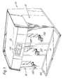
- a bulk brewer apparatus 10 including a right hand unit 12, a central unit 14 and a left hand unit 16, all within a common housing 18.
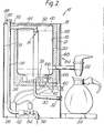
- the central unit 14 in the form of a hot water dispenser is shown in greater detail, having a tank 20 forming a hot water container and a draw-off tap 22 located towards the bottom of the tank 20.
- the tank 20 has an inner wall 19 and an outer wall 21, between which walls 19 and 21 a layer of insulating foam material is provided (for example the foam material as disclosed in GB Patent No. 1403861).
- a cast-in element heater 24 forms the base of tank 20, and mounted just above the base and supported by the heater casting is a thermostat phial 26 connected to a controller 28.
- a conduit 30 extends through the heater 24 to a drain plug 32 above a drip tray 34.
- Conduit 36 forms a small cold water container of small but nevertheless significant volume.
- another conduit 44 extends into the tank 20, the outlet 50 of the conduit 44 being located above a downwardly extending tube 52 positioned in the centre of the tank 20.
- the arrangement is such that an air brake is formed at the top of the tube 52, and cold water is fed down through the tube 52 to a position near the thermostat 26.
- the upper portion of the,tube 52 is provided with steam trap means 51 just below the outlet 50 of the conduit 44.
- Two embodiments of steam trap means 51 are shown in greater detail in Figures 4 and 5, and are described in detail below.
- a final conduit 46 of the 'T' junction 38 extends upwardly to a vent 48 to atmosphere to prevent any siphoning back.
- a solenoid operated valve 54 connected to regulator 42 so as to open or shut the supply of mains cold water from supply conduit 56.
- A.thermostat temperature control 60 for the heater 24 is provided movable between any setting between 50 0 C and 950C.
- a thermal safety cut-out 62 is also provided on the bottom of heater 24.
- Level indicating means 64 are also provided for the unit 14 comprising a pipe 66 extending from the base of the tank 20 and then up and along the side thereof.
- a window 68 is provided in the housing 18 whereby the water level in the pipe 66 (which will correspond to the actual water level in the tank 20) can be ascertained by a user.
- the cross-sectional area of the tube 66 relative the cross-sectional area of tank 20 is extremely small, in order to minimize heat loss.
- the pipe 66 extends from the base of the tank 20 also to minimize heat loss, since heat in the tank 20 will not travel-downward.
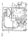
- the other two units 12 and 16 which are in the form of coffee and/or tea making units, each comprise a heater 102, spray head 104 and coffee infuse basket 106, all supported by the housing 18 of the apparatus 10. '
- Cold water is supplied to an inlet 108 of the heater 102 by means of a flexible pipe or conduit 110. Heated water then flows from the heater 102 through an outlet 112 to a flexible pipe or conduit 114 which passes up to the spray head 104 positioned above the coffee infuser basket 106.
- an electrical heating element 116 with electrical leads 118 extending from the top of the heater and connected to further electrical elements (not shown).
- the heater 102 is 'side hung' mounted to its particular support via a hinge (not shown) in order to allow access when necessary to other parts of the unit 12 or 16.
- the heater 102 is covered with a circular cover plate 120 in which the inlet 108 and outlet 112 are mounted.
- the cover 120 is secured to the heater by means of a wing nut 122 which screws into a central boss 124 on the heater.
- the heater 102 is provided with a drain cock 126 which screws into a hole 128 in the bottom of the heater and which is opened when necessary to drain the heater of any water.
- the units 12 and 16 also include a removable storing and dispensing container portion 130 having a draw-off tap 132.
- the container 130 has an outer wall 134 and an inner wall 136 between which a layer of insulating foam material is provided (for example material as disclosed in GB Patent No. 1403861, the contents of which are incorporated herewith by reference).
- the inlet 138 of the container (when positioned within the housing 18) is situated below the outlet of the basket 106, and is provided with steam trap means 140.
- the container 130 is conseqently independantly insulated such that there is only a 1 to 1.5°C drop every hour, and can be detachable from the rest of the apparatus 10 to dispense coffee/tea through tap 132 at a location distant from the rest of the apparatus.
- the container 130 has level indicating means 64 very similar to those described above and shown in Figure 2.
- FIG. 4 Two embodiments of steam trap means 51 and 140 are shown in greater detail in Figure 4 and 5.
- the tank 20 or container 130 has a screw on lid 142 to which a downwardly extending tube 144 is connected to feed hot water down to the base of the tank 20 or container 130 (see Figures 2 and 3).
- the itlet 138 is formed by a pipe 146 which extends into the centre of the tube 144.
- a U-shaped trap member 148 is supported just below the outlet of the pipe 146, such that the sides of the trap member 148 extend slightly above the lower edges of pipe 146 (see distance marked A in Figure 4).
- This arrangement acts as a steam trap since hot beverage passing through pipe 146 and into tube 144 will form a layer of liquid in the U-shaped trap member 148 preventing steam from inside the tank 20 or container 130 passing out through inlet 138.
- very small vent holes 145 and 147 are provided in tube 144 and_pipe 146 respectively.
- the tank 20 or container 130 is shown also having a screw-on lid 142 integral with a downwardly extending tube 144 which feeds hot water to the base of the tank 20 or container 130.
- the inlet 138 is formed by a hole in the lid, and the top of the tube 144 has a ledge 148 on which a trap ball 150 is supported.
- the trap ball 150 sealingly engages the ledge 148 and acts to prevent steam from inside the tank 20 or container 130 passing out through inlet 138.
- the trap ball 150 when hot water is passing through inlet 138 the trap ball 150 'floats' off the ledge 148 to allow water to pass through into tube 144, the ball 150 being retained in the inlet 138 by a pin 152.
- the lid 142 is also provided with a very small vent hole 154 in order to prevent any build up in pressure inside the tank 20 or container 130.
- the taps 22 and 132 shown in Figures 1 to 3 are shown in greater detail, having a housing portion 156 of plastics material and a valve arrangement 158.
- the valve arrangement 158 comprises a brass longitudinal stem 160 with a brass valve mounting member 157 for a silicon rubber valve element 159.
- a handle (not shown) is provided on the stem 160, at the other end from the valve element 159.
- the valve element 159 is biased by a spring 161 against a valve seat 162 which forms part of the tap housing portion 156 near the inner, wall 19 or 134 of the unit 12, 14 or 16.
- An 0-ring seal 164 is also provided to seal the spring 161 from liquid passing through the tap.
- the outlet 166 of the tap is positioned as far as possible from the outer wall 21 or 136 of the unit 12, 14 or 16 for the purposes of easy access.
- the outlet 166 is also positioned as close as possible to the outer wall 168 of the tap, and in this respect a ledge 170 to support the stem 160 is provided extending inwardly and past the outlet 166.
- a dispensing tube 172 may also be provided from the outlet 166.
- the handle (not shown) is operated to move the stem 160 outwards and thus lift the valve element 159 off the valve seat 162. Water from the container 130 thus flows past the valve element 159, through the housing 156 and finally out of the outlet 166.
- valve seat 162 well within the outer wall 19 or 136 of the unit, and secondly of a plastic housing 156 for the tap, causes minimal heat loss from the water in the unit through the tap.
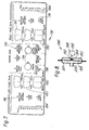
- the indicator panel 174 seen in Figure 1 is shown in greater detail.
- the panel 174 for the three units 12, 14 and 16 comprises a number of warning lights 176, on-off swtiches 178, "option" switches 180, indicator switches 182, and liquid level scales 184.
- a pressure warning device 186 having a housing 187 incorporating a silicon rubber diaphram 188 and a disc or table 190 connected to a spigot 192.
- a spring 194 around the spigot 192 is provided to bias the disc 190 against the diaphram 188, while the other end 196 of the spigot 192 is in contact with a microswitch 198.
- water for the apparatus 10 is passed through the inlet 200 of the housing 187, and acts against the diaphram 188 to move the disc 190 and spigot 192 towards-the microswitch 198. Should the water have a - dangerously high or low pressure, then the microswitch 198, which is pre-calibrated, will be activated to give an appropriate warning.
- a scale warning device 202 is shown in conjunction with a heating element 203, the device comprising a thermister 204 engaging a contact member 205.
- the heating element 203 will heat up to a temperature higher than its usual operating temperature and the thermister senses this and compares it electronically with a preset level, whereafter an appropriate warning will be given.
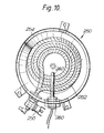
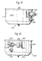
- a heater arrangement 250 as shown in Figures 10 to 12 having a heating element 252 can be used.
- the heater arrangement 250 has a housing 254 which forms the base of the tank 20, and which housing supports the heating element 252 which is spiralled to form three coils (as described in GB Patent Application No. 8621318 - the contents of which are incorporated herewith by reference).
- the element 252 is made from a material having a relatively high coefficient of expansion, whereby the coils expand in all directions when current is supplied via the electrical connections 256 and 258. When current is no longer passed through the coils, the coils contract, and this continual expansion and contraction tends to "crack off" scale from the curved surfaces of the element 252.
- a sensor 260 is supported by the housing 254. slightly above the element 252 in order to stop supply of current via the connections 256 and 258 when the element 252 is not fully covered by water or other liquid to be heated.
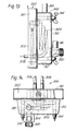
- the heater 300 shown in Figures 13 to 15 may be used.
- the heater arrangement 300 is supported behind the removable container 130, the heater arrangement 300 having a housing 302 supporting a heating element 304 which is spiralled to form three coils (as described in GB patent application no. 8621318).
- the element 304 is made from a material having a relatively high coefficient of expansion, whereby the coils expand in all directions when current is supplied via the electrical connections 306 and 3o8. When current is no longer passed through the coils, the coils contract, and this continual expansion and contraction tends to "crack off" scale from the curved surfaces of the element 304.
- the housing-302 comprises a rear housing portion 310 and a front housing portion 312, the front housing portion 312 being secured to the rear housing portion 310 by four wing nuts 314.
- the front housing portion 310 is provided with a cold water inlet 316 and a hot water outlet 318.
- the cold water inlet 316 has an adjustable water flow controller 320 in order to control the rate of flow of cold water into the heater arrangement 300.
- the apparatus 10 shown in Figure 1 which is capable of making and dispensing a large volume of liquid, is between 8 0 and 140 cm in length, between 60 and 70 cm in depth, and between 40 and 70 cm in width (not including tray 34).
- the apparatus 10 includes three separate units 12, 14 and 16, wherein each unit has its separate heating, storing and dispensing mechanisms. This leads to an arrangement having low energy consumption.
Landscapes
- Engineering & Computer Science (AREA)
- Food Science & Technology (AREA)
- Physics & Mathematics (AREA)
- Thermal Sciences (AREA)
- Chemical & Material Sciences (AREA)
- Combustion & Propulsion (AREA)
- Mechanical Engineering (AREA)
- General Engineering & Computer Science (AREA)
- Apparatus For Making Beverages (AREA)
Applications Claiming Priority (4)
| Application Number | Priority Date | Filing Date | Title |
|---|---|---|---|
| GB868600323A GB8600323D0 (en) | 1986-01-08 | 1986-01-08 | Heating & dispensing hot liquids |
| GB8600323 | 1986-01-08 | ||
| GB8621316 | 1986-09-04 | ||
| GB8621316A GB2185303B (en) | 1986-01-08 | 1986-09-04 | Apparatus for heating and dispensing hot liquids |
Publications (1)
| Publication Number | Publication Date |
|---|---|
| EP0228760A1 true EP0228760A1 (de) | 1987-07-15 |
Family
ID=26290184
Family Applications (1)
| Application Number | Title | Priority Date | Filing Date |
|---|---|---|---|
| EP86307054A Withdrawn EP0228760A1 (de) | 1986-01-08 | 1986-09-12 | Gerät zur Erwärmung und Abgabe heisser Flüssigkeiten |
Country Status (2)
| Country | Link |
|---|---|
| US (1) | US4927060A (de) |
| EP (1) | EP0228760A1 (de) |
Cited By (2)
| Publication number | Priority date | Publication date | Assignee | Title |
|---|---|---|---|---|
| EP0780079A1 (de) * | 1995-12-21 | 1997-06-25 | Reneka Industries | Individuelle Einheit zur Herstellung und Verabreichung von Kaffee, für eine Espressokaffeemaschine |
| FR2742645A1 (fr) * | 1995-12-21 | 1997-06-27 | Reneka Ind Sa | Machine a cafe dit "expresso" comprenant une chaudiere individuelle pour chaque groupe de preparation du cafe |
Families Citing this family (24)
| Publication number | Priority date | Publication date | Assignee | Title |
|---|---|---|---|---|
| US5509606A (en) * | 1993-10-04 | 1996-04-23 | Koltech, Inc. | Instant hot wash device |
| AU4233697A (en) * | 1996-08-06 | 1998-02-25 | Lancer Partnership, Ltd. | Flow control system for dispensers |
| US5836236A (en) * | 1997-03-03 | 1998-11-17 | Rolfes; Patrick J. | Coffee brewer and hot water dispenser |
| GB2334017A (en) * | 1998-02-05 | 1999-08-11 | Premark International Inc | Beverage dispenser |
| JP2881144B1 (ja) * | 1998-03-27 | 1999-04-12 | 株式会社グルメ杵屋 | レストランの調理システム |
| US6223938B1 (en) * | 1999-05-07 | 2001-05-01 | PARé SYLVAIN | Machine for dispensing a predetermined quantity of coffee |
| US6912357B2 (en) | 2002-01-29 | 2005-06-28 | Valeo Electrical Systems, Inc. | Fluid heater |
| US6789744B2 (en) | 2002-01-29 | 2004-09-14 | Valeo Electrical Systems, Inc. | Fluid heater with a variable mass flow path |
| USD489931S1 (en) | 2002-10-11 | 2004-05-18 | Global Marketing Corporation | Coffee maker |
| US6952524B2 (en) | 2002-11-27 | 2005-10-04 | Valeo Electrical Systems, Inc. | Fluid heater temperature balancing apparatus |
| US6782196B1 (en) | 2003-02-28 | 2004-08-24 | Valeo Electrical Systems, Inc. | Fluid heater with freeze protection |
| US6850699B2 (en) * | 2003-02-28 | 2005-02-01 | Valeo Electrical Systems, Inc. | Fluid heater temperature control apparatus and method |
| US6839509B2 (en) * | 2003-02-28 | 2005-01-04 | Valeo Electrical Systems, Inc. | Fluid heater control apparatus and method with overtemperature protection |
| US6889005B2 (en) * | 2003-04-04 | 2005-05-03 | Valeo Electrical Systems, Inc. | Fluid heater with compressible cover freeze protection |
| US7190893B2 (en) * | 2003-06-27 | 2007-03-13 | Valeo Electrical Systems, Inc. | Fluid heater with low porosity thermal mass |
| US20050019028A1 (en) * | 2003-07-25 | 2005-01-27 | Karl-Heinz Kuebler | Fluid heater with integral heater elements |
| US20050047768A1 (en) * | 2003-08-29 | 2005-03-03 | Valeo Electrical Systems, Inc. | Fluid heater with integral heater element ground connections |
| ITMO20040202A1 (it) * | 2004-07-30 | 2004-10-30 | Illycaffe Spa | Metodi ed apparati per ottenere bevande. |
| US20060144873A1 (en) * | 2004-12-28 | 2006-07-06 | Tiger Corporation | Liquid container |
| KR100760500B1 (ko) | 2006-03-23 | 2007-10-04 | 김갑수 | 온냉 탕약용 약탕기 |
| EP2208450A1 (de) * | 2009-01-14 | 2010-07-21 | Nestec S.A. | Modulsystem mit autonomem Modul mit kleinem Empfangsbereich |
| IT1393999B1 (it) * | 2009-04-01 | 2012-05-17 | Rancilio Macchine Caffe | Macchina per la preparazione di infusi, in particolare caffe' espresso, gruppo erogatore e metodo di realizzazione della stessa |
| EP2703739B1 (de) * | 2012-08-31 | 2015-07-29 | Electrolux Home Products Corporation N.V. | Kochherd mit Ofeninnenraum und Dampfkochanordnung |
| CN104771074A (zh) * | 2015-05-04 | 2015-07-15 | 马卓娅 | 一种饮料机 |
Citations (7)
| Publication number | Priority date | Publication date | Assignee | Title |
|---|---|---|---|---|
| US1837552A (en) * | 1929-02-02 | 1931-12-22 | Henry D Kelly | Coffee urn faucet |
| USRE22022E (en) * | 1942-02-10 | Coffee-making device | ||
| US2490501A (en) * | 1945-02-21 | 1949-12-06 | Jr Richard C Ashenden | Coffee-making apparatus |
| US3149556A (en) * | 1960-01-08 | 1964-09-22 | Bunn Capitol Company | Coffee making machine |
| US3485162A (en) * | 1968-04-01 | 1969-12-23 | Universal Oil Prod Co | Beverage preparation and dispensing apparatus |
| GB1403861A (en) * | 1971-07-14 | 1975-08-28 | Smith Wellstood G G Ltd | Heat insulation hotcupboards |
| US4361750A (en) * | 1980-08-28 | 1982-11-30 | General Electric Company | Drip coffeemaker having a condenser eliminating delivery of steam to the water spreader |
Family Cites Families (7)
| Publication number | Priority date | Publication date | Assignee | Title |
|---|---|---|---|---|
| US1464981A (en) * | 1922-04-08 | 1923-08-14 | Fenton John | Lady's boot |
| US3084047A (en) * | 1959-07-29 | 1963-04-02 | Nat Vendors Inc | Vending machine |
| US3556347A (en) * | 1968-11-01 | 1971-01-19 | Amseco Corp | Multiple station beverage dispensing system having auxiliary control valve means |
| US3691932A (en) * | 1971-07-06 | 1972-09-19 | Bunn O Matic Corp | Apparatus for supplying hot water for coffee brewing purposes |
| US4455477A (en) * | 1980-04-16 | 1984-06-19 | Zip Heaters (Aust) Pty. Limited | Electric boiling water heater |
| US4638928A (en) * | 1984-05-29 | 1987-01-27 | Newco Enterprises, Inc. | Hot beverage container |
| US4771680A (en) * | 1986-08-11 | 1988-09-20 | W. M. Still & Sons Limited | Tea brewing apparatus |
-
1986
- 1986-09-12 EP EP86307054A patent/EP0228760A1/de not_active Withdrawn
-
1988
- 1988-04-28 US US07/187,289 patent/US4927060A/en not_active Expired - Lifetime
Patent Citations (7)
| Publication number | Priority date | Publication date | Assignee | Title |
|---|---|---|---|---|
| USRE22022E (en) * | 1942-02-10 | Coffee-making device | ||
| US1837552A (en) * | 1929-02-02 | 1931-12-22 | Henry D Kelly | Coffee urn faucet |
| US2490501A (en) * | 1945-02-21 | 1949-12-06 | Jr Richard C Ashenden | Coffee-making apparatus |
| US3149556A (en) * | 1960-01-08 | 1964-09-22 | Bunn Capitol Company | Coffee making machine |
| US3485162A (en) * | 1968-04-01 | 1969-12-23 | Universal Oil Prod Co | Beverage preparation and dispensing apparatus |
| GB1403861A (en) * | 1971-07-14 | 1975-08-28 | Smith Wellstood G G Ltd | Heat insulation hotcupboards |
| US4361750A (en) * | 1980-08-28 | 1982-11-30 | General Electric Company | Drip coffeemaker having a condenser eliminating delivery of steam to the water spreader |
Cited By (2)
| Publication number | Priority date | Publication date | Assignee | Title |
|---|---|---|---|---|
| EP0780079A1 (de) * | 1995-12-21 | 1997-06-25 | Reneka Industries | Individuelle Einheit zur Herstellung und Verabreichung von Kaffee, für eine Espressokaffeemaschine |
| FR2742645A1 (fr) * | 1995-12-21 | 1997-06-27 | Reneka Ind Sa | Machine a cafe dit "expresso" comprenant une chaudiere individuelle pour chaque groupe de preparation du cafe |
Also Published As
| Publication number | Publication date |
|---|---|
| US4927060A (en) | 1990-05-22 |
Similar Documents
| Publication | Publication Date | Title |
|---|---|---|
| US4927060A (en) | Apparatus with steam trap for heating and dispensing hot liquids | |
| US7980422B2 (en) | Portable beverage dispenser with electronic beverage characteristic display and method | |
| US4917005A (en) | Beverage brewer with brewing temperature interlock | |
| CA1217948A (en) | Beverage making machine with hot water faucet | |
| US4478139A (en) | Beverage making machine | |
| US3869968A (en) | Coffee maker | |
| NO122550B (de) | ||
| US8171843B1 (en) | Coffee maker with automatic metered filling means | |
| EP0690689B1 (de) | Schnell-heisswasserspender | |
| US20010012448A1 (en) | Method for preparing infant formula from powder with dispensing and filtering means | |
| GB2162052A (en) | Beverage-making device | |
| US20150132458A1 (en) | Hot beverage maker | |
| CA2047376C (en) | Device for supplying boiling water | |
| US5560284A (en) | Automatic drip brewing urn | |
| US2346389A (en) | Beverage production | |
| GB2143031A (en) | Hot water dispenser | |
| CA1238073A (en) | Boilers or tanks for hot water | |
| JPS6248143B2 (de) | ||
| US3494276A (en) | Cold water pour in beverage apparatus | |
| GB2185303A (en) | Heating a plurality of liquids | |
| GB2064078A (en) | Water boiler | |
| CN217440856U (zh) | 加热龙头 | |
| JPH02150658A (ja) | 媒体用の加熱器具 | |
| EP3106774B1 (de) | Vorrichtung zur abgabe von kochendem wasser | |
| EP0295098A1 (de) | Warmwasserboiler |
Legal Events
| Date | Code | Title | Description |
|---|---|---|---|
| PUAI | Public reference made under article 153(3) epc to a published international application that has entered the european phase |
Free format text: ORIGINAL CODE: 0009012 |
|
| AK | Designated contracting states |
Kind code of ref document: A1 Designated state(s): CH DE FR GB LI NL SE |
|
| 17P | Request for examination filed |
Effective date: 19870818 |
|
| 17Q | First examination report despatched |
Effective date: 19890705 |
|
| STAA | Information on the status of an ep patent application or granted ep patent |
Free format text: STATUS: THE APPLICATION IS DEEMED TO BE WITHDRAWN |
|
| 18D | Application deemed to be withdrawn |
Effective date: 19901225 |
|
| RIN1 | Information on inventor provided before grant (corrected) |
Inventor name: HAYES, CECIL Inventor name: SNOWBALL, MALCOLM ROBERT |