EP0228768A2 - Medical appliance for the hand - Google Patents
Medical appliance for the hand Download PDFInfo
- Publication number
- EP0228768A2 EP0228768A2 EP86307731A EP86307731A EP0228768A2 EP 0228768 A2 EP0228768 A2 EP 0228768A2 EP 86307731 A EP86307731 A EP 86307731A EP 86307731 A EP86307731 A EP 86307731A EP 0228768 A2 EP0228768 A2 EP 0228768A2
- Authority
- EP
- European Patent Office
- Prior art keywords
- thumb
- hand
- digits
- bag
- pressure
- Prior art date
- Legal status (The legal status is an assumption and is not a legal conclusion. Google has not performed a legal analysis and makes no representation as to the accuracy of the status listed.)
- Granted
Links
Images




Classifications
-
- A—HUMAN NECESSITIES
- A61—MEDICAL OR VETERINARY SCIENCE; HYGIENE
- A61H—PHYSICAL THERAPY APPARATUS, e.g. DEVICES FOR LOCATING OR STIMULATING REFLEX POINTS IN THE BODY; ARTIFICIAL RESPIRATION; MASSAGE; BATHING DEVICES FOR SPECIAL THERAPEUTIC OR HYGIENIC PURPOSES OR SPECIFIC PARTS OF THE BODY
- A61H9/00—Pneumatic or hydraulic massage
- A61H9/005—Pneumatic massage
- A61H9/0078—Pneumatic massage with intermittent or alternately inflated bladders or cuffs
-
- A—HUMAN NECESSITIES
- A61—MEDICAL OR VETERINARY SCIENCE; HYGIENE
- A61H—PHYSICAL THERAPY APPARATUS, e.g. DEVICES FOR LOCATING OR STIMULATING REFLEX POINTS IN THE BODY; ARTIFICIAL RESPIRATION; MASSAGE; BATHING DEVICES FOR SPECIAL THERAPEUTIC OR HYGIENIC PURPOSES OR SPECIFIC PARTS OF THE BODY
- A61H2205/00—Devices for specific parts of the body
- A61H2205/06—Arms
- A61H2205/065—Hands
Definitions
- This invention relates to a medical appliance, and particularly to an appliance for applying local pressure to a part of the hand for the purpose of stimulating blood circulation through enhanced venous-return flow.
- Such medical appliances comprise a double-walled sheath adapted to fit over a limb, for example, an arm or a calf and foot to be treated, and a pump apparatus arranged to inflate and deflate the sheath cyclically, thereby to apply a pumping action to the limb and thus assist venous blood-flow therein.
- a particular disadvantage of such known devices is that they cannot be used when the limb to be treated is also to be encased in a plaster cast. Also, they are of inherently large-volume capacity with large area coverage of the involved limb, so that their action is on an entire limb; large-capacity pumping apparatus is required for administration of an inflation/deflation cycle, and more than one pump region may be activated simultaneously, to the detriment of achieving optimum venous-return flow. In particular, these known devices do not permit localized application of pumping pressures.
- venous-pump mechanism in the region of the hand which is essentially limited to the proximal phalanges of the digits and thumb, and to the adjacent region of the palm; this mechanism is naturally brought into operation upon a tight doubling of the fist, whereupon venous-return flow ensues from the entire arm.
- a tight fist squeezes this region, which is a major locale of blood accumulation, i.e., in readiness for venous return through the arm.
- venous-return flow may be efficiently stimulated, even in the case of a degree of venous obstruction in the wrist or elsewhere in the involved arm.
- the invention achieves the above objects by localizing the periodic application of squeezing force, essentially limited to the phalanx of the digits and thumb, and to the adjacent region of the palm of the hand.
- an inflatable mitt is applied to the said proximal phalanges and adjacent regions, with extremities of digits and thumb projecting beyond the mitt.
- the mitt may be wrapped with suitable fabric, such as surgical gauze or muslin, to provide a circumferential tie of the inflatable regions, the tie providing hoop-tension reference for inward application of a squeezing pressure/release cycle; and the squeeze is applied in unison circumferentially around each of the individual digits (and thumb) at the phalanx region.
- suitable fabric such as surgical gauze or muslin
- the inflatable mitt may be embedded in an orthopedic cast, without impairing the application of pulsed pressure local to the indicated region; in this case, the circumferential tie is provided by the cast.
- FIGs. 1 to 3 the invention is shown in application to an inflatable mitt 10 which comprises two like inflatable bags 11-12 of flexible material, secured to each other only at certain points, and each of the bags is served by its own pipe or supply connection 13-14.
- These connections 13-14 are in turn served in unison by a single pumping apparatus 15, with sufficient capacity and control to deliver pressure fluid with full application of squeezing pressure to the hand-pump region of the hand, in one second or less, as will be more fully discussed in connection with Fig. 7.
- the pressure fluid is suitably air.
- the bags 11-12 may be image duplicates of each other. As shown, bag 11 comprises inner and outer panels 16-17 of like peripheral contour bonded continuously around the periphery and to the pressure-fluid connection tube 13. A continuous heat seal, indented by reason of local compression for greater reinforcement of the bonding, follows a peripheral course 18, which is delineated by stippling in the drawing.
- each of the panels 16-17 is cut follows a forward or distal contour 19 which is designed to lap the first phalanges bones and, generally speaking, conforms to the alignment of the joints between first and second phalanges bones for a.flattened hand, so that both panels 16-17 cover the phalanx of the digits of the hand (i.e., the first phalanges bones of all digits).
- the forward contour 19 merges with a thumb-side or lateral contour 20 which laps or traverses the joint between the phalanges of the thumb; the forward contour 19 merges at its other end with an opposite-side or lateral contour 21 which extends to proximal- lateral juncture with the supply tube 13; and both lateral contours 20-21 merge with a proximal transverse contour 22 which also extends to proximal- lateral juncture with tube 13.
- bonded tab formations 23-24 of panels 16-17 extend in laterally opposite directions from proximal regions of the lateral contours 20-21.
- the peripheral course 18 of the continuous reinforcing seal of panels 16-17 is characterized by limited longitudinal adjacency to pipe 13 at A (Fig. 2), truncation of tab 23 at B, a first inward lobe at C between thumb and forefinger locations, similar but more narrow lobes at D-E-F between adjacent digits, truncation of tab 24 at G, and finally by limited longitudinal adjacency to pipe 13 at H.
- the inner panel 16 may be of porous material or may be perforated for limited escape of inflation fluid during intervals between pulsed inflation, thus producing a cooling action upon adjacent skin; and as a further comfort to the patient, the skin-contacting surface of panel 16 is preferably flock-coated, as suggested by stippling at 29 In Fig. 2A.
- the other bag 12 may be of construction identical to that of bag 11; however, for the case of a flock-coated skin-contacting surface 29' of bag 12, the construction identity is a mirror-image identity. Corresponding parts of bag 12 are given the same number identification as for bag 11, but with primed notation.
- the mitt 10 becomes a unitary article upon bringing both bags 11-12 in mirror-image adjacency and registration of locating apertures 27-28 of the respective bags.
- compression heat-sealing is effected marginally outside the seal course 18, locally at B', and at C', D', E', F', and G', thus establishing intervening unsealed peripheral spaces (between bags 11-12), which spaces enable individual thumb and digit passage, to develop the inserted-hand condition of Fig. 1.
- seals B'-C' must be sufficient for circumferential embrace of the thumb, while the spans between adjacent distal ends of seals C'-D', of seals D'-E', of seals E'-F', and of F'-G', must also be sufficient for circumferential embrace of the respective digits which individually pass therethrough.
- the mitt of Figs. 1 to 3 is selected for size appropriate to the hand size and hand condition of the patient. For example, a severely swollen hand may call for a mitt of larger size than the patient might otherwise require.
- the appearance will be as depicted in Fig. 1, with sealed alignments C '-D'-E'-P' extending deep into each crotch between the thumb and the forefinger and between adjacent digits.
- the tabs 23-24 of bag 11 are drawn toward each other and are adhesively secured to panel 17, as by first removing local protective strips 23"-24" to expose a local coat of pressure-sensitive adhesive, and then drawing the tab inwardly to effectively narrow the proximal or wrist-end opening of the mitt.
- a similar local fastening of corresponding tabs 23'-24' of bag 12 to the outer panel 17' of bag 12 will aid in adapting the wrist opening to the patient.
- a circumferential tie may then be developed by orthopedic-cast techniques, if necessary around all or part of the mitt, making sure that the tube connections 13-14 become externally accessible for service connection to the inflation pulsing means 15. In the form shown, however, it is assumed that a cast is not necessary, at least in the region of the mitt, and in Fig.
- surgical gauze or muslin 30 may be wrapped around the palm and dorsum and over the phalanx region of the digits and thumb, thus establishing a circumferential tie around the hand-pump region; alternatively, if the outer panels 17-17' of bags 11-12 are of relatively non-stretch material, these panels 17-17' may in some cases provide a sufficient circumferential tie.
- the circumferential tie will be understood to effectively confine bags 16-17 against outward expansion in the inflation/deflation cycle, and at the same time to substantially limit the volumetric requirements for recycled supply of pressure fluid in the inflation/deflation cycle.
- squeezing pressure at the phalanx, is effectively localized to the circumference of the thumb, to the circumference of each digit, and to adjacent regions of the palm and dorsum of the hand, and all vein accumulations of blood within this limited (phalanx and adjacent palm) region are constricted simultaneously, in imitation of a clenched-fist actuation of the hand pump.
- the thumb and all digits remain exposed, as for periodic inspection of circulation, for nerve-reaction testing, and for inspection of therapeutic progress in reduction of swelling.
- Figs. 4 and 5 illustrate another embodiment wherein a single inflatable bag 40 is so formed as to provide inflation/deflation action at the indicated phalanx and adjacent areas of dorsum and palm of the hand.
- the bag 40 comprises two like panels 41-42 of generally rectangular outline, wherein four digit openings 43-44-45-46 are in spaced transverse array at the longitudinal middle of the rectangular outline; at symmetrically located longitudinal and transverse offset from the array 43 ... 46 are two further openings 47-48, each of which is sized for thumb accommodation.
- a course 49 of bonded seal extends around the entire rectangular periphery and is completed to an inflation pipe connection 50; this seal course is indicated by stippling, as is also a similar circumferentially complete seal of panels 41-42 to each other around each of the thumb and digit openings 43 ... 48.
- the panel 41 which is to be applied adjacent the skin is flock-coated for comfort, and this panel may also be porous, foraminated or punctured, for venting of pressure fluid during periods between pulsed inflations of the bag.
- the digits are inserted through openings 43 ... 46 with the thumb accommodated through opening 47; and if the left hand is to be treated, the digits are served by the same openings while the thumb is passed through opening 48.
- separate halves of the bag are folded-back to lap regions of the dorsum and palm adjacent the phalanx of the thumb and digits. Lateral edges 51-52 of the bag are then overlapped, as suggested in Fig. 5 for a left-hand situation.
- Adhesive tape can retain the wrapped condition while an orthopedic cast is being applied, or a circumferential tie can be established by wrapped gauze or muslin in the manner described in connection with Fig. 3. Pulsed cycles of inflation/deflation action will be seen to focus squeezing, vein-compressing local forces simultaneously around the thumb and each digit, at the phalanx and adjacent regions of the palm.
- the embodiment of Fig. 6 provides stimulation action similar to that afforded by the embodiment of Figs. 4 and 5, but with greater economy of panel sheet material.
- the inflatable bag 60 of Fig. 6 will be understood to comprise two like panels 61-62 of flexible sheet material which are peripherally bonded and sealed to each other and to a pressure-fluid connection 63, the course of peripheral seal being shown by stippling.
- Four digit openings 64-65-66-67 are in spaced slightly arcuate array, and a thumb opening 68 is at offset therefrom; and each of these openings is the site of a local circumferential seal of panels 61-62 to each other, as suggested by stippling.
- Peripheral profiling is characterized by a generally straight proximal edge L and by divergent lobe or tab contours M-N along the opposite edge, beyond the digit openings.
- both panels 61-62 have flock-coated outer surfaces, so that a right hand may be served by thumb and digit insertions via the panel-61 side of the bag, and so that a left hand is similarly served via the panel-62 side.
- the tab formations M-N are folded back over the dorsum of the involved hand, and adhesive tape will temporarily retain the wrapped application pending gauze, muslin and/or orthopedic-cast development of a circumferential tie.
- the maximum inflated volume is in the order of 200 cc, and on deflation the inflated volume can be expected to reduce to 75 to 100 cc.
- the pressure-fluid supply equipment 15 may be relatively small and convenient for table-top or shelf-mounting, with flexible-hose and disconnectable coupling to the inlet pipe (13-14, 50, 63); this .
- the supply and control means 15 is merely timed valving to assure programmed delivery of pressure pulses of a fluid, such as oxygen from a locally available tank supply, or the means 15 incorporates its own pumping and/or accumulator mechanism to provide the needed pressure fluid.
- a fluid such as oxygen from a locally available tank supply
- the means 15 incorporates its own pumping and/or accumulator mechanism to provide the needed pressure fluid.
- time-delay devices and their adjustability. are all well known and therefore the supply means 15 may take on a variety of different physical embodiments. What is important, however, is that delivery of pressure fluid to the inlet (13-14, 50, 63) and the bleed of fluid through pores and/or apertures and/or valving in the deflation phase shall meet certain criteria. Presently preferred criteria will be stated in the context of Fig. 7, which shows pressure P to develop quickly in the inflation phase a and to dissipate somewhat exponentially, in the deflation phase b.
- the inflatable device should be inflated in one second or less, it is perhaps more accurate to state that in our experience to date the inflation should be as quick as possible, to imitate the speed with which involved veins are compressionally squeezed in a quick clenching of the fist.
- Such fast inflation imparts a jerk or sharply pulsed action in return-blood flow, and such action is believed to be helpful in reducing swelling and pain. It is believed that maximum velocity, however transient upon pulsed excitation, is more important than total blood flow.
- each check valve has check-valve formations, and the downstream side of each check valve is a trap-like situs for undesired accumulation of solids or clotting which may not otherwise be flushed through the venous-return system; it is believed that with bag inflation as rapid as possible, the opening phase for each check valve is correspondingly rapid, thus locally stirring trapped return-flow blood and reducing the chances of a clotting constriction of return-flow passages.
- the peak pressure P for any delivered inflation impulse should be that which is sufficient to produce the appropriate venous impulse, whilst not being too uncomfortable for the patient to tolerate.
- the total period (a+b) of the inflation/deflation cycle will also be various, depending upon the confronting pathological condition and, in particular, on the severity of venous obstruction and on how quickly the physiological venous pump becomes filled.
- the period of the cycle might be as frequent as every 10 seconds. In moderate swelling, 30 seconds would probably be adequate, whereas 'for maintenance purposes a 60-second cycle should suffice.
- the frequency of the cycle can be audibly monitored by the clinician, listening to the flow in posterior veins of the radius or ulna with a Doppler monitor.
- the interval between inflation pulses is very much greater than the indicated rapid inflation time a, it is our further experience that the deflation time should be as short as possible, with deflation commencing automatically at achievement of predetermined peak pressure.
- a timer within apparatus 15 reinitiates the cycle upon predetermined time-out of the interval b.
- an inflatable mitt is provided by an inner glove 80 within an outer glove 81, the finger and thumb extremities of both gloves being truncated, to allow for installed exposure of these extremities of the hand, when the mitt is in use.
- These gloves are sealed to each other, via peripherally continuous seals 82-83-84-85-86 around each of the thumb and finger openings, and by another such seal 87 around the wrist opening.
- a reinforcement patch 88 is shown protecting the point of inflation-tube (89) entry to the bag region defined by and between the sealed gloves 80-81.
- the outer glove 81 is of relatively non-stretchable material, as compared to the relatively flexible and stretchable nature of the inner glove 80, then the outer glove 81 in some cases may provide an adequate circumferential tie; generally, however, a gauze wrap as in Fig. 3 is preferred, for greater limitation of the requisite inflation volume.
- Fig. 9 The embodiment of Fig. 9 will be recognized for its similarity to Fig. 8, and therefore the same reference numbers have been used where appropriate.
- the difference in Fig. 9 is that a peripherally continuous seal 90 is developed between gloves 80-81 around the dorsum and palm, in order to further limit the requisite inflation of the device.
- the gloves 80-81 may be merely laminated to each other.
- inflation/deflation procedures are as described for other embodiments.
- the panels 61-62 may be bonded to each other within the entire area of tab formations M-N, i.e., outwardly of a sealed inflation perimeter which runs a course 70 suggested by phantom lines, in closely spaced distal adjacency to the digit openings 64 ... 67. That being the case, the tab formations M-N are not part of the inflatable volume but they can be folded back over the dorsum and adhesively or otherwise integrated into the circumferential-tie development.
- the pulse pressures are applied with at least equal effectiveness, circumferentially and individually around the proximal phalanges of the thumb and all digits, and to the adjacent region of the palm. This result is achieved without applying inflation pressure directly against the dorsum of the hand; however, in reaction to development of inflation pressure directly over the involved palm-side region, the dorsum receives an indirect application of pressure via hoop tension in the circumferential tie.
Landscapes
- Health & Medical Sciences (AREA)
- Epidemiology (AREA)
- Pain & Pain Management (AREA)
- Physical Education & Sports Medicine (AREA)
- Rehabilitation Therapy (AREA)
- Life Sciences & Earth Sciences (AREA)
- Animal Behavior & Ethology (AREA)
- General Health & Medical Sciences (AREA)
- Public Health (AREA)
- Veterinary Medicine (AREA)
- Massaging Devices (AREA)
- Orthopedics, Nursing, And Contraception (AREA)
Abstract
Description
- This invention relates to a medical appliance, and particularly to an appliance for applying local pressure to a part of the hand for the purpose of stimulating blood circulation through enhanced venous-return flow.
- Such medical appliances are known which comprise a double-walled sheath adapted to fit over a limb, for example, an arm or a calf and foot to be treated, and a pump apparatus arranged to inflate and deflate the sheath cyclically, thereby to apply a pumping action to the limb and thus assist venous blood-flow therein.
- A particular disadvantage of such known devices is that they cannot be used when the limb to be treated is also to be encased in a plaster cast. Also, they are of inherently large-volume capacity with large area coverage of the involved limb, so that their action is on an entire limb; large-capacity pumping apparatus is required for administration of an inflation/deflation cycle, and more than one pump region may be activated simultaneously, to the detriment of achieving optimum venous-return flow. In particular, these known devices do not permit localized application of pumping pressures.
- In our European Patent Application No. 86306163.6 we disclose a variety of inflatable devices of relatively low volumetric capacity and specifically adapted to stimulate venous-return flow in a human leg, by localized action beneath the mid-tarsal region of the foot, whereby a major locale of blood accumulation is periodically squeezed, to force or,to enhance the force of venous-return flow. The local nature of these inflatable devices enables them to be encased in a cast if necessary, and the toes are always exposed, thus permitting inspection of circulation, swelling, nerve-reaction and other indicia of treatment progress.
- We have discovered a venous-pump mechanism in the region of the hand which is essentially limited to the proximal phalanges of the digits and thumb, and to the adjacent region of the palm; this mechanism is naturally brought into operation upon a tight doubling of the fist, whereupon venous-return flow ensues from the entire arm. A tight fist squeezes this region, which is a major locale of blood accumulation, i.e., in readiness for venous return through the arm. And we have established that by periodically squeezing this region without requiring a patient to double his fist, i.e., by external application of squeezing pressure essentially local to this region, venous-return flow may be efficiently stimulated, even in the case of a degree of venous obstruction in the wrist or elsewhere in the involved arm.
- It is accordingly an object of the invention to provide an improved method and means of stimulating the flow of blood in a human arm.
- It is a specific object to provide means whereby periodic application of pressure to a relatively limited and localized region of the hand may efficiently stimulate or assist the venous-return flow in the involved arm.
- It is another specific object to meet the above objects with structure which will permit continuous exposure of the extremities of the thumb and digits of the involved hand, without interrupting or disturbing the therapy involved in the periodic application of pressure.
- The invention achieves the above objects by localizing the periodic application of squeezing force, essentially limited to the phalanx of the digits and thumb, and to the adjacent region of the palm of the hand. To this end, and for the embodiments to be described, an inflatable mitt is applied to the said proximal phalanges and adjacent regions, with extremities of digits and thumb projecting beyond the mitt. The mitt may be wrapped with suitable fabric, such as surgical gauze or muslin, to provide a circumferential tie of the inflatable regions, the tie providing hoop-tension reference for inward application of a squeezing pressure/release cycle; and the squeeze is applied in unison circumferentially around each of the individual digits (and thumb) at the phalanx region. Alternatively, the inflatable mitt may be embedded in an orthopedic cast, without impairing the application of pulsed pressure local to the indicated region; in this case, the circumferential tie is provided by the cast.
- The invention will be described in detail for various embodiments, in conjunction with the accompanying drawings, in which:
- Fig. 1 is generally a plan view, looking at the palm side of a hand which has been inserted into an inflatable mitt of the invention;
- Fig. 2 is a plan view of the mitt of Fig. 1, in flattened condition prior to hand insertion;
- Fig. 2A is a fragmentary sectional view taken at 2A-2A in Fig. 2, for an expanded-mitt condition;
- Fig. 3 is a view similar to Fig. 1, after wrapping with gauze or muslin, and therefore in readiness for therapeutic use;
- Fig. 4 is a plan view of another inflatable embodiment, in flattened condition, prior to use;
- . Fig. 5 is a view similar to Fig. 1 but for the purpose of showing hand insertion in the embodiment of Fig. 4;
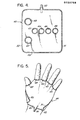
- Fig. 6 is a plan view of still another inflatable embodiment in flattened condition;
- Fig. 7 is a simple graph of pressure as a function of time, in aid of discussion of use of the invention; and
- Figs. 8 and 9 are similar views of two further inflatable embodiments of the invention.
- Referring initially to Figs. 1 to 3, the invention is shown in application to an
inflatable mitt 10 which comprises two like inflatable bags 11-12 of flexible material, secured to each other only at certain points, and each of the bags is served by its own pipe or supply connection 13-14. These connections 13-14 are in turn served in unison by asingle pumping apparatus 15, with sufficient capacity and control to deliver pressure fluid with full application of squeezing pressure to the hand-pump region of the hand, in one second or less, as will be more fully discussed in connection with Fig. 7. The pressure fluid is suitably air. - The bags 11-12 may be image duplicates of each other. As shown, bag 11 comprises inner and outer panels 16-17 of like peripheral contour bonded continuously around the periphery and to the pressure-
fluid connection tube 13. A continuous heat seal, indented by reason of local compression for greater reinforcement of the bonding, follows aperipheral course 18, which is delineated by stippling in the drawing. - The blank to which each of the panels 16-17 is cut follows a forward or
distal contour 19 which is designed to lap the first phalanges bones and, generally speaking, conforms to the alignment of the joints between first and second phalanges bones for a.flattened hand, so that both panels 16-17 cover the phalanx of the digits of the hand (i.e., the first phalanges bones of all digits). Theforward contour 19 merges with a thumb-side orlateral contour 20 which laps or traverses the joint between the phalanges of the thumb; theforward contour 19 merges at its other end with an opposite-side or lateral contour 21 which extends to proximal- lateral juncture with thesupply tube 13; and both lateral contours 20-21 merge with a proximaltransverse contour 22 which also extends to proximal- lateral juncture withtube 13. As shown, bonded tab formations 23-24 of panels 16-17 extend in laterally opposite directions from proximal regions of the lateral contours 20-21. - The
peripheral course 18 of the continuous reinforcing seal of panels 16-17 is characterized by limited longitudinal adjacency topipe 13 at A (Fig. 2), truncation oftab 23 at B, a first inward lobe at C between thumb and forefinger locations, similar but more narrow lobes at D-E-F between adjacent digits, truncation oftab 24 at G, and finally by limited longitudinal adjacency to pipe 13 at H. Small triangular fillet areas 25-26 near region A and betweenseal 18 andproximal contour 22, and between lobe C andlateral contour 20, are shown with apertures 27-28 which will be understood to provide alignment registry with jig pins (not shown) for production assembly of the panels 16-17 prior to and during bonding and sealing steps of manufacture. - The
inner panel 16 may be of porous material or may be perforated for limited escape of inflation fluid during intervals between pulsed inflation, thus producing a cooling action upon adjacent skin; and as a further comfort to the patient, the skin-contacting surface ofpanel 16 is preferably flock-coated, as suggested by stippling at 29 In Fig. 2A. - As indicated above, the
other bag 12 may be of construction identical to that of bag 11; however, for the case of a flock-coated skin-contacting surface 29' ofbag 12, the construction identity is a mirror-image identity. Corresponding parts ofbag 12 are given the same number identification as for bag 11, but with primed notation. - The
mitt 10 becomes a unitary article upon bringing both bags 11-12 in mirror-image adjacency and registration of locating apertures 27-28 of the respective bags. Thus registered, compression heat-sealing is effected marginally outside theseal course 18, locally at B', and at C', D', E', F', and G', thus establishing intervening unsealed peripheral spaces (between bags 11-12), which spaces enable individual thumb and digit passage, to develop the inserted-hand condition of Fig. 1. It will be understood that the span between adjacent distal ends of seals B'-C' must be sufficient for circumferential embrace of the thumb, while the spans between adjacent distal ends of seals C'-D', of seals D'-E', of seals E'-F', and of F'-G', must also be sufficient for circumferential embrace of the respective digits which individually pass therethrough. - In use, the mitt of Figs. 1 to 3, is selected for size appropriate to the hand size and hand condition of the patient. For example, a severely swollen hand may call for a mitt of larger size than the patient might otherwise require. Upon hand insertion, the appearance will be as depicted in Fig. 1, with sealed alignments C'-D'-E'-P' extending deep into each crotch between the thumb and the forefinger and between adjacent digits. Next, the tabs 23-24 of bag 11 are drawn toward each other and are adhesively secured to
panel 17, as by first removing localprotective strips 23"-24" to expose a local coat of pressure-sensitive adhesive, and then drawing the tab inwardly to effectively narrow the proximal or wrist-end opening of the mitt. A similar local fastening of corresponding tabs 23'-24' ofbag 12 to the outer panel 17' ofbag 12 will aid in adapting the wrist opening to the patient. A circumferential tie may then be developed by orthopedic-cast techniques, if necessary around all or part of the mitt, making sure that the tube connections 13-14 become externally accessible for service connection to the inflation pulsing means 15. In the form shown, however, it is assumed that a cast is not necessary, at least in the region of the mitt, and in Fig. 3 it is illustrated that surgical gauze ormuslin 30 may be wrapped around the palm and dorsum and over the phalanx region of the digits and thumb, thus establishing a circumferential tie around the hand-pump region; alternatively, if the outer panels 17-17' of bags 11-12 are of relatively non-stretch material, these panels 17-17' may in some cases provide a sufficient circumferential tie. - The circumferential tie will be understood to effectively confine bags 16-17 against outward expansion in the inflation/deflation cycle, and at the same time to substantially limit the volumetric requirements for recycled supply of pressure fluid in the inflation/deflation cycle. As a practical matter, squeezing pressure, at the phalanx, is effectively localized to the circumference of the thumb, to the circumference of each digit, and to adjacent regions of the palm and dorsum of the hand, and all vein accumulations of blood within this limited (phalanx and adjacent palm) region are constricted simultaneously, in imitation of a clenched-fist actuation of the hand pump. Importantly, the thumb and all digits remain exposed, as for periodic inspection of circulation, for nerve-reaction testing, and for inspection of therapeutic progress in reduction of swelling.
- Figs. 4 and 5 illustrate another embodiment wherein a single
inflatable bag 40 is so formed as to provide inflation/deflation action at the indicated phalanx and adjacent areas of dorsum and palm of the hand. Specifically, thebag 40 comprises two like panels 41-42 of generally rectangular outline, wherein four digit openings 43-44-45-46 are in spaced transverse array at the longitudinal middle of the rectangular outline; at symmetrically located longitudinal and transverse offset from thearray 43 ... 46 are two further openings 47-48, each of which is sized for thumb accommodation. Acourse 49 of bonded seal extends around the entire rectangular periphery and is completed to aninflation pipe connection 50; this seal course is indicated by stippling, as is also a similar circumferentially complete seal of panels 41-42 to each other around each of the thumb anddigit openings 43 ... 48. Preferably, thepanel 41 which is to be applied adjacent the skin is flock-coated for comfort, and this panel may also be porous, foraminated or punctured, for venting of pressure fluid during periods between pulsed inflations of the bag. - If the right hand is to be treated with the device of Fig. 4, then the digits are inserted through
openings 43 ... 46 with the thumb accommodated through opening 47; and if the left hand is to be treated, the digits are served by the same openings while the thumb is passed through opening 48. Upon hand insertion, separate halves of the bag are folded-back to lap regions of the dorsum and palm adjacent the phalanx of the thumb and digits. Lateral edges 51-52 of the bag are then overlapped, as suggested in Fig. 5 for a left-hand situation. Adhesive tape can retain the wrapped condition while an orthopedic cast is being applied, or a circumferential tie can be established by wrapped gauze or muslin in the manner described in connection with Fig. 3. Pulsed cycles of inflation/deflation action will be seen to focus squeezing, vein-compressing local forces simultaneously around the thumb and each digit, at the phalanx and adjacent regions of the palm. - The embodiment of Fig. 6 provides stimulation action similar to that afforded by the embodiment of Figs. 4 and 5, but with greater economy of panel sheet material. Specifically, the
inflatable bag 60 of Fig. 6 will be understood to comprise two like panels 61-62 of flexible sheet material which are peripherally bonded and sealed to each other and to a pressure-fluid connection 63, the course of peripheral seal being shown by stippling. Four digit openings 64-65-66-67 are in spaced slightly arcuate array, and athumb opening 68 is at offset therefrom; and each of these openings is the site of a local circumferential seal of panels 61-62 to each other, as suggested by stippling. Peripheral profiling is characterized by a generally straight proximal edge L and by divergent lobe or tab contours M-N along the opposite edge, beyond the digit openings. - Preferably, both panels 61-62 have flock-coated outer surfaces, so that a right hand may be served by thumb and digit insertions via the panel-61 side of the bag, and so that a left hand is similarly served via the panel-62 side. Once inserted, the tab formations M-N are folded back over the dorsum of the involved hand, and adhesive tape will temporarily retain the wrapped application pending gauze, muslin and/or orthopedic-cast development of a circumferential tie.
- An inflatable device of the nature described in connection with any of the present embodiments, in conjunction with its circumferential tie, never requires a large volume change in proceeding through its inflation/deflation cycle. The maximum inflated volume is in the order of 200 cc, and on deflation the inflated volume can be expected to reduce to 75 to 100 cc. Thus, the pressure-
fluid supply equipment 15 may be relatively small and convenient for table-top or shelf-mounting, with flexible-hose and disconnectable coupling to the inlet pipe (13-14, 50, 63); this.is true, whether the supply and control means 15 is merely timed valving to assure programmed delivery of pressure pulses of a fluid, such as oxygen from a locally available tank supply, or themeans 15 incorporates its own pumping and/or accumulator mechanism to provide the needed pressure fluid. Whatever the alternative, time-delay devices and their adjustability.are all well known and therefore the supply means 15 may take on a variety of different physical embodiments. What is important, however, is that delivery of pressure fluid to the inlet (13-14, 50, 63) and the bleed of fluid through pores and/or apertures and/or valving in the deflation phase shall meet certain criteria. Presently preferred criteria will be stated in the context of Fig. 7, which shows pressure P to develop quickly in the inflation phase a and to dissipate somewhat exponentially, in the deflation phase b. - Although it has been stated above that the inflatable device should be inflated in one second or less, it is perhaps more accurate to state that in our experience to date the inflation should be as quick as possible, to imitate the speed with which involved veins are compressionally squeezed in a quick clenching of the fist. Such fast inflation imparts a jerk or sharply pulsed action in return-blood flow, and such action is believed to be helpful in reducing swelling and pain. It is believed that maximum velocity, however transient upon pulsed excitation, is more important than total blood flow. The veins have check-valve formations, and the downstream side of each check valve is a trap-like situs for undesired accumulation of solids or clotting which may not otherwise be flushed through the venous-return system; it is believed that with bag inflation as rapid as possible, the opening phase for each check valve is correspondingly rapid, thus locally stirring trapped return-flow blood and reducing the chances of a clotting constriction of return-flow passages.
- The peak pressure P for any delivered inflation impulse should be that which is sufficient to produce the appropriate venous impulse, whilst not being too uncomfortable for the patient to tolerate.
- This will of course mean a different peak pressure P which will be various, depending upon the particular patient and his affliction. However, it can be said that, in our experience to date, a peak pressure within the inflatable device of 200 to 220-mm Hg has been satisfactory. Such peak pressure has produced comfortable actuation of the patient's hand pump, in the circumstance wherein the
supply apparatus 15 has provided time-switched delivery of oxygen from a pressurized tank and, alternatively, in the circumstance wherein thesupply apparatus 15 has generated its own delivery of pressurized pulses of local air; in both cases, the inflation time a was approximately 0.4 second. - The total period (a+b) of the inflation/deflation cycle will also be various, depending upon the confronting pathological condition and, in particular, on the severity of venous obstruction and on how quickly the physiological venous pump becomes filled. As a rough guide, it can be said that in severe venous obstruction, as in a limb with marked swelling, the period of the cycle might be as frequent as every 10 seconds. In moderate swelling, 30 seconds would probably be adequate, whereas 'for maintenance purposes a 60-second cycle should suffice. The frequency of the cycle can be audibly monitored by the clinician, listening to the flow in posterior veins of the radius or ulna with a Doppler monitor.
- Although the interval between inflation pulses is very much greater than the indicated rapid inflation time a, it is our further experience that the deflation time should be as short as possible, with deflation commencing automatically at achievement of predetermined peak pressure. Thus, we currently recommend bag leakage or other inflation relief to the extent that, for example, for a peak pressure P of 210-mm Hg, deflation to 30-mm Hg should be in about one second, and to 20-mm Hg in about 1.9 seconds. A timer within
apparatus 15 reinitiates the cycle upon predetermined time-out of the interval b. - In the embodiment of Fig. 8, an inflatable mitt is provided by an
inner glove 80 within anouter glove 81, the finger and thumb extremities of both gloves being truncated, to allow for installed exposure of these extremities of the hand, when the mitt is in use. These gloves are sealed to each other, via peripherally continuous seals 82-83-84-85-86 around each of the thumb and finger openings, and by another such seal 87 around the wrist opening. Areinforcement patch 88 is shown protecting the point of inflation-tube (89) entry to the bag region defined by and between the sealed gloves 80-81. If theouter glove 81 is of relatively non-stretchable material, as compared to the relatively flexible and stretchable nature of theinner glove 80, then theouter glove 81 in some cases may provide an adequate circumferential tie; generally, however, a gauze wrap as in Fig. 3 is preferred, for greater limitation of the requisite inflation volume. - The embodiment of Fig. 9 will be recognized for its similarity to Fig. 8, and therefore the same reference numbers have been used where appropriate. The difference in Fig. 9 is that a peripherally continuous seal 90 is developed between gloves 80-81 around the dorsum and palm, in order to further limit the requisite inflation of the device. At the proximal or wrist side of the seal 90 the gloves 80-81 may be merely laminated to each other. In both Fig. 8 and Fig. 9, inflation/deflation procedures are as described for other embodiments.
- While the invention has been described in detail in connection with illustrative embodiments, it will be understood that modifications may be made without departing from the invention. For example, in the case of Fig. 6; the panels 61-62 may be bonded to each other within the entire area of tab formations M-N, i.e., outwardly of a sealed inflation perimeter which runs a
course 70 suggested by phantom lines, in closely spaced distal adjacency to the digit openings 64 ... 67. That being the case, the tab formations M-N are not part of the inflatable volume but they can be folded back over the dorsum and adhesively or otherwise integrated into the circumferential-tie development. It is to be noted that in this event, the pulse pressures are applied with at least equal effectiveness, circumferentially and individually around the proximal phalanges of the thumb and all digits, and to the adjacent region of the palm. This result is achieved without applying inflation pressure directly against the dorsum of the hand; however, in reaction to development of inflation pressure directly over the involved palm-side region, the dorsum receives an indirect application of pressure via hoop tension in the circumferential tie.
Claims (18)
Applications Claiming Priority (2)
| Application Number | Priority Date | Filing Date | Title |
|---|---|---|---|
| US80959085A | 1985-12-16 | 1985-12-16 | |
| US809590 | 1991-12-17 |
Publications (3)
| Publication Number | Publication Date |
|---|---|
| EP0228768A2 true EP0228768A2 (en) | 1987-07-15 |
| EP0228768A3 EP0228768A3 (en) | 1987-09-09 |
| EP0228768B1 EP0228768B1 (en) | 1991-12-11 |
Family
ID=25201701
Family Applications (1)
| Application Number | Title | Priority Date | Filing Date |
|---|---|---|---|
| EP19860307731 Expired EP0228768B1 (en) | 1985-12-16 | 1986-10-07 | Medical appliance for the hand |
Country Status (7)
| Country | Link |
|---|---|
| EP (1) | EP0228768B1 (en) |
| DE (1) | DE3682888D1 (en) |
| DK (1) | DK167335B1 (en) |
| ES (1) | ES2007024A6 (en) |
| GR (1) | GR862883B (en) |
| IE (1) | IE59480B1 (en) |
| PT (1) | PT83814B (en) |
Cited By (1)
| Publication number | Priority date | Publication date | Assignee | Title |
|---|---|---|---|---|
| EP0344949A3 (en) * | 1988-05-31 | 1990-06-06 | Novamedix Ltd. | Medical appliance for the hand |
Family Cites Families (4)
| Publication number | Priority date | Publication date | Assignee | Title |
|---|---|---|---|---|
| US3153413A (en) * | 1962-01-23 | 1964-10-20 | Jobst Institute | Pressure bandage-splint |
| DE2606729C3 (en) * | 1976-02-19 | 1980-07-17 | Hermann 2000 Hamburg Mohr | Device for therapeutic treatment |
| US4479490A (en) * | 1978-04-17 | 1984-10-30 | Dedo Richard G | Cast padding |
| GB2141938B (en) * | 1983-06-22 | 1986-11-12 | Arthur Michael Newsam Gardner | Medical appliance |
-
1986
- 1986-10-07 EP EP19860307731 patent/EP0228768B1/en not_active Expired
- 1986-10-07 DE DE8686307731T patent/DE3682888D1/en not_active Expired - Lifetime
- 1986-10-08 IE IE265486A patent/IE59480B1/en not_active IP Right Cessation
- 1986-10-14 ES ES8602577A patent/ES2007024A6/en not_active Expired
- 1986-11-26 PT PT8381486A patent/PT83814B/en not_active IP Right Cessation
- 1986-12-09 DK DK591386A patent/DK167335B1/en not_active IP Right Cessation
- 1986-12-10 GR GR862883A patent/GR862883B/en unknown
Cited By (1)
| Publication number | Priority date | Publication date | Assignee | Title |
|---|---|---|---|---|
| EP0344949A3 (en) * | 1988-05-31 | 1990-06-06 | Novamedix Ltd. | Medical appliance for the hand |
Also Published As
| Publication number | Publication date |
|---|---|
| DE3682888D1 (en) | 1992-01-23 |
| EP0228768A3 (en) | 1987-09-09 |
| DK591386A (en) | 1987-06-17 |
| GR862883B (en) | 1987-04-27 |
| PT83814B (en) | 1993-01-29 |
| EP0228768B1 (en) | 1991-12-11 |
| PT83814A (en) | 1986-12-01 |
| IE862654L (en) | 1987-06-16 |
| DK167335B1 (en) | 1993-10-18 |
| IE59480B1 (en) | 1994-03-09 |
| DK591386D0 (en) | 1986-12-09 |
| ES2007024A6 (en) | 1989-06-01 |
Similar Documents
| Publication | Publication Date | Title |
|---|---|---|
| US4809684A (en) | Pressure appliance for the hand for aiding circulation | |
| US4846160A (en) | Method of promoting circulation in the hand | |
| USRE32940E (en) | Medical appliance | |
| US4696289A (en) | Method of promoting venous pump action | |
| US4614179A (en) | Medical appliance | |
| US4721101A (en) | Medical appliance | |
| AU749610B2 (en) | Device for pressurizing limbs | |
| CA2216368C (en) | A medical device for the hand | |
| US4453538A (en) | Medical apparatus | |
| EP0750487B1 (en) | Medical appliance for intermittent compression treatment | |
| US6478757B1 (en) | Device for pressurizing limbs | |
| US4614180A (en) | Medical appliance | |
| CA2286583C (en) | Lymphedema treatment system | |
| US7767874B2 (en) | Medical device and process | |
| US3391692A (en) | Variable-pressure casing and method of using for therapeutic purposes | |
| EP0228768B1 (en) | Medical appliance for the hand | |
| GB1599607A (en) | Device for applying presure to a patients limb | |
| EP2436350A2 (en) | Compression Garment Having Grip | |
| CA2112882C (en) | Medical appliance for intermittently pulsed compression of proximal joints and adjacent tissue of the human body | |
| AU719881B2 (en) | A medical device for the hand | |
| GB2433034A (en) | Centrifugal massage device |
Legal Events
| Date | Code | Title | Description |
|---|---|---|---|
| PUAI | Public reference made under article 153(3) epc to a published international application that has entered the european phase |
Free format text: ORIGINAL CODE: 0009012 |
|
| AK | Designated contracting states |
Kind code of ref document: A2 Designated state(s): BE DE FR GB IT LU NL |
|
| PUAL | Search report despatched |
Free format text: ORIGINAL CODE: 0009013 |
|
| AK | Designated contracting states |
Kind code of ref document: A3 Designated state(s): BE DE FR GB IT LU NL |
|
| 17P | Request for examination filed |
Effective date: 19880309 |
|
| RAP1 | Party data changed (applicant data changed or rights of an application transferred) |
Owner name: NOVAMEDIX LTD |
|
| 17Q | First examination report despatched |
Effective date: 19890807 |
|
| GRAA | (expected) grant |
Free format text: ORIGINAL CODE: 0009210 |
|
| AK | Designated contracting states |
Kind code of ref document: B1 Designated state(s): BE DE FR GB IT LU NL |
|
| REF | Corresponds to: |
Ref document number: 3682888 Country of ref document: DE Date of ref document: 19920123 |
|
| ITF | It: translation for a ep patent filed | ||
| ET | Fr: translation filed | ||
| PLBE | No opposition filed within time limit |
Free format text: ORIGINAL CODE: 0009261 |
|
| STAA | Information on the status of an ep patent application or granted ep patent |
Free format text: STATUS: NO OPPOSITION FILED WITHIN TIME LIMIT |
|
| 26N | No opposition filed | ||
| REG | Reference to a national code |
Ref country code: FR Ref legal event code: CA |
|
| EPTA | Lu: last paid annual fee | ||
| ITPR | It: changes in ownership of a european patent |
Owner name: CAMBIO SEDE;NOVAMEDIX LTD |
|
| REG | Reference to a national code |
Ref country code: GB Ref legal event code: 732E |
|
| REG | Reference to a national code |
Ref country code: FR Ref legal event code: TP |
|
| NLS | Nl: assignments of ep-patents |
Owner name: NOVAMEDIX DISTRIBUTION LTD. |
|
| REG | Reference to a national code |
Ref country code: GB Ref legal event code: IF02 |
|
| PGFP | Annual fee paid to national office [announced via postgrant information from national office to epo] |
Ref country code: FR Payment date: 20050825 Year of fee payment: 20 |
|
| PGFP | Annual fee paid to national office [announced via postgrant information from national office to epo] |
Ref country code: DE Payment date: 20050929 Year of fee payment: 20 |
|
| PGFP | Annual fee paid to national office [announced via postgrant information from national office to epo] |
Ref country code: NL Payment date: 20051003 Year of fee payment: 20 |
|
| PGFP | Annual fee paid to national office [announced via postgrant information from national office to epo] |
Ref country code: GB Payment date: 20051005 Year of fee payment: 20 |
|
| PGFP | Annual fee paid to national office [announced via postgrant information from national office to epo] |
Ref country code: IT Payment date: 20051027 Year of fee payment: 20 |
|
| PGFP | Annual fee paid to national office [announced via postgrant information from national office to epo] |
Ref country code: LU Payment date: 20051031 Year of fee payment: 20 |
|
| PGFP | Annual fee paid to national office [announced via postgrant information from national office to epo] |
Ref country code: BE Payment date: 20051215 Year of fee payment: 20 |
|
| PG25 | Lapsed in a contracting state [announced via postgrant information from national office to epo] |
Ref country code: GB Free format text: LAPSE BECAUSE OF EXPIRATION OF PROTECTION Effective date: 20061006 |
|
| PG25 | Lapsed in a contracting state [announced via postgrant information from national office to epo] |
Ref country code: NL Free format text: LAPSE BECAUSE OF EXPIRATION OF PROTECTION Effective date: 20061007 |
|
| REG | Reference to a national code |
Ref country code: GB Ref legal event code: PE20 |
|
| NLV7 | Nl: ceased due to reaching the maximum lifetime of a patent |
Effective date: 20061007 |
|
| BE20 | Be: patent expired |
Owner name: *NOVAMEDIX DISTRIBUTIONS LTD Effective date: 20061007 |