EP0228848A2 - Appareil de reproduction de disques - Google Patents
Appareil de reproduction de disques Download PDFInfo
- Publication number
- EP0228848A2 EP0228848A2 EP86309710A EP86309710A EP0228848A2 EP 0228848 A2 EP0228848 A2 EP 0228848A2 EP 86309710 A EP86309710 A EP 86309710A EP 86309710 A EP86309710 A EP 86309710A EP 0228848 A2 EP0228848 A2 EP 0228848A2
- Authority
- EP
- European Patent Office
- Prior art keywords
- transducer
- disc
- tracks
- speed
- signal
- Prior art date
- Legal status (The legal status is an assumption and is not a legal conclusion. Google has not performed a legal analysis and makes no representation as to the accuracy of the status listed.)
- Granted
Links
Images


Classifications
-
- G—PHYSICS
- G11—INFORMATION STORAGE
- G11B—INFORMATION STORAGE BASED ON RELATIVE MOVEMENT BETWEEN RECORD CARRIER AND TRANSDUCER
- G11B21/00—Head arrangements not specific to the method of recording or reproducing
- G11B21/02—Driving or moving of heads
- G11B21/08—Track changing or selecting during transducing operation
-
- G—PHYSICS
- G11—INFORMATION STORAGE
- G11B—INFORMATION STORAGE BASED ON RELATIVE MOVEMENT BETWEEN RECORD CARRIER AND TRANSDUCER
- G11B19/00—Driving, starting, stopping record carriers not specifically of filamentary or web form, or of supports therefor; Control thereof; Control of operating function ; Driving both disc and head
- G11B19/20—Driving; Starting; Stopping; Control thereof
-
- G—PHYSICS
- G11—INFORMATION STORAGE
- G11B—INFORMATION STORAGE BASED ON RELATIVE MOVEMENT BETWEEN RECORD CARRIER AND TRANSDUCER
- G11B21/00—Head arrangements not specific to the method of recording or reproducing
- G11B21/02—Driving or moving of heads
- G11B21/08—Track changing or selecting during transducing operation
- G11B21/081—Access to indexed tracks or parts of continuous track
-
- G—PHYSICS
- G11—INFORMATION STORAGE
- G11B—INFORMATION STORAGE BASED ON RELATIVE MOVEMENT BETWEEN RECORD CARRIER AND TRANSDUCER
- G11B7/00—Recording or reproducing by optical means, e.g. recording using a thermal beam of optical radiation by modifying optical properties or the physical structure, reproducing using an optical beam at lower power by sensing optical properties; Record carriers therefor
- G11B7/08—Disposition or mounting of heads or light sources relatively to record carriers
- G11B7/085—Disposition or mounting of heads or light sources relatively to record carriers with provision for moving the light beam into, or out of, its operative position or across tracks, otherwise than during the transducing operation, e.g. for adjustment or preliminary positioning or track change or selection
Definitions
- the present invention relates to a disc reproducing apparatus for reproducing signals from a disc bearing digital signals.
- an optical disc (hereinafter, referred to as a compact disc) on which digital audio signals are recorded, when a target reproduction start position is accessed, the number of tracks over which an optical pickup will traverse until the optical pickup reaches the target start position is calculated using the data of a TOC (table of contents) and the optical pickup is moved on the basis of this count value.
- the disc reproducing apparatus is provided with a track detecting circuit to count the number of tracks over which the optical pickup will traverse and to signal when the optical pickup has arrived at the target track.
- Fig. 1 shows an example of such a conventional track detecting circuit.
- the conventional track detecting circuit detects the number of traverse tracks by use of the reproduced RF signal from the optical pickup.
- this circuit to detect the number of traverse tracks using the reproduced RF signal, for example, there is also known a way to detect the number of traverse tracks by using a tracking servo signal as shown in the Official Gazette of Japanese Patent Examined Publication No. 28054/1985.
- the RF signal is input to a terminal 51.
- the input terminal 51 is connected to the anodes of diodes 53 and 54 through a capacitor 52.
- a capacitor 55 and a resistor 56 are connected in parallel between a cathode of the diode 53 and the ground, respectively.
- a series circuit of resistors 57 and 58 is inserted between the cathode of the diode 53 and the ground.
- a node of the resistors 57 and 58 is connected to one input terminal of a comparator 59.
- a capacitor 60 and a resistor 61 are connected in parallel between a cathode of the diode 54 and the ground, respectively.
- the cathode of the diode 54 is connected to the other input terminal of the comparator 59.
- An output terminal 62 is led out of an output terminal of the comparator 59.
- the reproduced RF signal is supplied from the optical pickup to the input terminal 51.
- the optical pickup is fed at a high speed, e.g., 8 cm/sec, as shown in Fig. 2, track detection outputs corresponding to the traverse of tracks 64 on a disc 63 by the optical pickup appear in the RF signal together with outputs of the pits.
- the RF signal including the pit outputs and track detection outputs as mentioned above is input to the input terminal 51 and transmitted through the coupling capacitor 52 to the diodes 53 and 54 as the signal from which the DC component is removed as shown in Fig. 3.
- the RF signal derived through the capacitor 52 is rectified by the diodes 53,and 54, respectively.
- a filter consisting of the capacitor 55 and resistor 56 is connected to the diode 53.
- the filter consisting of the capacitor 55 and resistor 56 is designed to have a large time constant, so that the output of the diode 53 is averaged.
- the averaged output is output from the node of the resistors 57 and 58.
- the filter composed of the capacitor 60 and resistor 61 is connected to the diode 54 and is designed to have a time constant small enough to remove the frequency components of the pits.
- the pit frequency components are removed from the output of the diode 54 and only the track detection output is supplied to the other input of the comparator 59.
- the track detection output is compared with the average level which is output from the node of the resistors 57 and 58 by the comparator 59.
- a pulse corresponding to the traverse over the tracks 64 by the optical pickup is output from the terminal 62.
- Digital data is EFM modulated and recorded on the compact disc.
- the interval (track pitch) between the tracks of the respective pits formed on the compact disc is 1. 6 ⁇ m.
- the feed speed of the optical pickup is set to, e.g., 8cm/sec. Therefore, assuming that the feed speed of the optical pickup is 8 cm/sec, the frequency of the track detection signal becomes 50 kHz.
- the feed speed of the optical pickup is set to, e.g., 8 cm/sec.
- an access time for the optical pickup of 0.4 to 0.5 seconds is required to move the optical pickup to the target reproduction start position, and 0.3 seconds is needed to search the target track number, so that a total time of about 0.8 seconds is necessary. If the feed speed of the optical pickup is raised, the access time can be reduced. In particular, for the case where not only digital audio signals but also various kinds of digital data were recorded on the compact disc, there is a strong demand to reduce the access time by increasing the feed speed of the optical pickup.
- the feed speed of the pickup can be sufficiently increased.
- the problem occurs that the track detection signal cannot be obtained when the feed speed of the pickup is raised.
- the pit frequency component is 200 kHz. Therefore, if the frequency of the track detection signal is 100 kHz above the frequency of 1/2 of this pit component, no track can be detected in accordance with the theorem of sampling.
- the tracks can in practice be detected when the frequency of the track detection signal is below 50 kHz.
- the frequency of the track detection signal becomes 50 kHz when the track pitch is 1.6 ⁇ m, namely, when the feed speed is 8 cm/sec. In other words, when the feed speed is made faster than 8 cm/sec, the frequency of the track detection signal increases and the tracks cannot be detected.
- an object of the invention to provide a disc reproducing apparatus which can detect the tracks even when the optical pickup is moved at a high speed.
- a disc reproducing apparatus of the invention when the optical pickup is fed at a high speed, the disc is rotated at a speed higher than that in the ordinary playback mode, causing the pit frequency component to increase, for example, from 200 kHz to 400 kHz.
- This increased rotational speed of the disc allows the frequency of the track detection signal to be raised and the data pit components of the RF signal are removed by a filter having a selectable time constant.
- the invention also provides a method of reproducing signals recorded in circular tracks on a disc comprising the steps of rotating the disc at a first speed, reproducing signals recorded on the disc while it is being rotated at said first speed by means of a transducer positioned over a selected track on said disc, and simultaneously rotating said disc at a second, higher speed, moving the transducer radially across the disc from one track to another, and counting the number of tracks crossed by means of the signals reproduced by the transducer.
- a reference signal generator 1 generates a reference clock signal CK 1 and a reference clock signal CK 2 having a frequency which is twice as high as that of the clock signal CK 1 .
- Either one of the reference clocks CK 1 and CK 2 is selectively output from the generator 1 in response to the output of a switching signal generator 2.
- the switching signal generator is controlled by the disc player controller (not shown) which also controls the feed, i.e. the access movement of the optical pickup 8.
- the reference clock signal CK 1 is output.
- the reference clock signal CK 2 is output.
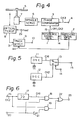
- the reference signal generator 1 is constituted in a manner such that the output clock signal CK 1 of the frequency f 1 from an oscillator 11 and the output clock signal CK 2 of the frequency f 2 from an oscillator 12 are supplied to an electronic switching circuit 13 and either one of the clocks CK 1 and CK 2 is selectively supplied to an output terminal 1 5 under the control of the switching signal from the switching signal generator 2 which is supplied to a control terminal 14 of the switch 13.
- the generator 1 may be also constituted in the manner shown in Fig. 6. Namely, the clock signal CK 2 of the frequency f 2 is supplied to a terminal 16. The clock signal CK 2 is frequency divided by a 1/2 frequency divider 17 to form the clock signal CK 1 of the frequency f l .
- the clocks CK 1 and CK 2 are selected by AND gates 18 and 19 by the switching signal which is directly supplied to the AND gate 18 from a terminal 20 and also supplied through an invertor 21 to the AND gate 19. The selected one of the clocks CK 1 and CK 2 is supplied to an output terminal 23 through an OR gate 22.
- the reference clock signal CK 1 or CK 2 which is output from the generator 1 is supplied to a phase comparator 3.
- a clock signal CK 3 is extracted by conventional circuitry (not shown) from the reproduced RF signal of an optical disc 5 and is supplied at a terminal 4 to the comparator 3.
- the clock signal CK 3 from the terminal 4 is phase compared with the reference clock signal CK 1 or CK 2 by the phase comparator 3 and the resultant difference signal is supplied to a spindle servo circuit 6.
- a control signal based on the difference signal is formed by the spindle servo circuit 6.
- a spindle motor 7 is rotated at a constant linear velocity in response to the control signal.
- the control of the spindle motor is disclosed in U.S. Patent No. 4,397,011 by the same applicant as the present invention.
- the reproduced RF signal of the optical disc 5 from an optical pickup 8 is supplied to a track detecting circuit 9.
- the time constant of a filter to remove the pit component can be switched by the output of the switching signal generator 2.
- the track detecting circuit 9 is constituted as shown in Fig. 7.
- the RF signal is input to a terminal 31.
- the input terminal 31 is connected to the anodes of diodes 33 and 34 through a capacitor 32.
- a capacitor 35 and a resistor 36 are connected in parallel between a cathode of the diode 33 and the ground.
- a series circuit of resistors 37 and 38 is inserted between the cathode of the diode 33 and the ground.
- a node of the resistors 37 and 38 is connected to one input terminal of a comparator 39.
- a capacitor 40 and a resistor 41 are connected in parallel between a cathode of the diode 34 and the ground.
- One end of a capacitor 42 is connected to the cathode of the diode 34.
- the other end of the capacitor 42 is grounded through a switching circuit 43.
- the ON/OFF operations of the switching circuit 43 are controlled by a switch control signal from the switching signal generator 2 which is supplied to a terminal 44.
- the cathode of the diode 34 is connected to the other input terminal of the comparator 39.
- An output terminal 10 is led out of the comparator 39.
- the reproduced RF signal from the optical pickup 8 is supplied to the input terminal 31.
- the RF signal is supplied through the capacitor 32 and is rectified by the diodes 33 and 34.
- a filter consisting of the capacitor 35 and resistor 36 is connected to the diode 33.
- the filter consisting of the capacitor 35 and resistor 36 is designed to have a large time constant, so that the output of the diode 33 is averaged.
- the averaged output is output from the junction of the resistors 37 and 38.
- a filter composed of the resistor 41 and capacitors 40 and 42 is connected to the diode 34. This filter removes the pit components from the detected signal.
- the time constant of this filter is designed to have a large value when the switching circuit 43 is turned on and it is designed to have a small value when the switching circuit 43 is turned off.
- the time constant is designed to have a value large enough to remove the pit component when the disc 5 is rotated at the rotational speed in the ordinary playback mode.
- the time constant is designed to have a value small enough to remove the pit component when the disc 5 is rotated at a rotational speed which is twice as high as that in the ordinary playback mode.
- the pit component is removed from the output of the diode 34 and only the track detection'output is supplied to the input of the comparator 39.
- the track detection output is compared with the average level which is output from the node of the resistors 37 and 38 by the comparator 39.
- a pulse corresponding to the traverse of the tracks on the disc 5 by the optical pickup 8 is supplied to the output terminal 10.
- this track detection signal When accessing the target reproduction start position, this track detection signal, as shown in Fig. 8, is supplied from an input terminal 25 to a counter 26. The number of tracks over which the optical pickup 8 has traversed is counted by this counter from the track detection signal. The number of tracks over which the optical pickup 8 will traverse until the target reproduction start position is reached is calculated by a microprocessor (not shown) of the disc reproducing apparatus by use of the data of the TOC. The count value of the number of tracks is set into a target setting circuit 27 to set a desired number of traverse tracks. The track number set in the target setting circuit 27 is compared with the count value of the counter 26 by a comparator 28. When they coincide, a stop feed signal is output from an output terminal 29 to stop the radial movement of the optical pickup 8.
- the reference clock signal CK 1 is supplied from the reference signal generator 1 to the phase comparator 3 in response to the output of the switching signal generator 2.
- the rotation of the disc 5 is controlled by the clock signal CK 1 .
- the reference clock signal CK 2 having a frequency which is twice as high as the reference clock signal CK 1 , is simultaneously supplied to the phase comparator 3 in response to the switching signal generator 2.
- the rotation of the disc 5 is controlled by the clock signal CK 2 . Therefore, when the reproduction start position is accessed, the disc 5 is rotated at a rotational speed which is twice as high as that in the ordinary playback mode.
- the pit frequency component When the rotational speed of the disc 5 is twice as high as that in the ordinary playback mode, the pit frequency component is also double that in the ordinary playback mode. Since the pit frequency component in the ordinary playback mode is about 200 kHz, by setting the rotational speed of the disc 5 to be twice the speed in the ordinary playback mode, the pit frequency component upon access of the reproduction start position becomes about 400 kHz.
- the tracks can be detected if the frequency of the track detection signal is 200 kHz below 1/2 of the pit frequency component on the basis of the theorem of sampling.
- the tracks can be detected if the frequency of the track detection signal is below 1 0 0 kHz. Therefore, the feed speed of the optical pickup 8 can be set to 16 cm/sec.
- the disc 5 is simultaneously rotated at a high speed, so that the access feed speed can be raised. But this causes the pit frequency component to also be increased. Therefore, to detect the tracks even in the case of the high pit frequency component, the time constant of the filter to remove the pit frequency component of the track detecting circuit 9 can be switched.
- the track detecting circuit 9 is not limited to a construction such that the tracks are detected only using the reproduced RF signal but may also be constituted so as to detect the tracks using a tracking servo signal.
- the invention can also be similarly applied to the optical disc on which a video signal was recorded.
- the rotational speed of the disc is set to be higher than the rotational speed in the ordinary playback mode, so that the pit frequency component rises.
- a filter having a selectable time constant is used to remove the pit component frequency from the detected signal. Therefore, a shorter time constant is selected for the filter. Therefore, the feed speed can be raised while still allowing track crossings to be detected.
- the disc rotational speed in the high speed feeding mode is set to be twice as high as that in the ordinary playback mode
- the optical pickup can be fed at, e.g., 16 cm/sec. Consequently, when the reproduction start position is accessed, the moving time of the optical pickup can be reduced to, e.g., 0.2 to 0.3 seconds and the access time can be also decreased to 0.5 to 0.6 seconds.
Landscapes
- Rotational Drive Of Disk (AREA)
- Moving Of The Head For Recording And Reproducing By Optical Means (AREA)
- Moving Of Head For Track Selection And Changing (AREA)
- Transition And Organic Metals Composition Catalysts For Addition Polymerization (AREA)
- Automatic Disk Changers (AREA)
- Feeding And Guiding Record Carriers (AREA)
- Input Circuits Of Receivers And Coupling Of Receivers And Audio Equipment (AREA)
- Signal Processing For Digital Recording And Reproducing (AREA)
- Optical Recording Or Reproduction (AREA)
Priority Applications (1)
| Application Number | Priority Date | Filing Date | Title |
|---|---|---|---|
| AT86309710T ATE55200T1 (de) | 1985-12-20 | 1986-12-12 | Plattenwiedergabegeraet. |
Applications Claiming Priority (2)
| Application Number | Priority Date | Filing Date | Title |
|---|---|---|---|
| JP60287549A JPH0760564B2 (ja) | 1985-12-20 | 1985-12-20 | デイスク再生装置 |
| JP287549/85 | 1985-12-20 |
Publications (3)
| Publication Number | Publication Date |
|---|---|
| EP0228848A2 true EP0228848A2 (fr) | 1987-07-15 |
| EP0228848A3 EP0228848A3 (en) | 1988-01-07 |
| EP0228848B1 EP0228848B1 (fr) | 1990-08-01 |
Family
ID=17718774
Family Applications (1)
| Application Number | Title | Priority Date | Filing Date |
|---|---|---|---|
| EP86309710A Expired - Lifetime EP0228848B1 (fr) | 1985-12-20 | 1986-12-12 | Appareil de reproduction de disques |
Country Status (7)
| Country | Link |
|---|---|
| US (1) | US4825431A (fr) |
| EP (1) | EP0228848B1 (fr) |
| JP (1) | JPH0760564B2 (fr) |
| KR (1) | KR950000423B1 (fr) |
| AT (1) | ATE55200T1 (fr) |
| CA (1) | CA1277420C (fr) |
| DE (1) | DE3673147D1 (fr) |
Cited By (3)
| Publication number | Priority date | Publication date | Assignee | Title |
|---|---|---|---|---|
| EP0277793A3 (en) * | 1987-02-02 | 1990-08-29 | Sony Corporation | Access control apparatus |
| EP0491573A3 (en) * | 1990-12-19 | 1993-01-20 | Sharp Kabushiki Kaisha | Optical disk drive |
| EP0411961A3 (en) * | 1989-08-04 | 1993-03-03 | Sharp Kabushiki Kaisha | Optical disk recording/reproducing device |
Families Citing this family (4)
| Publication number | Priority date | Publication date | Assignee | Title |
|---|---|---|---|---|
| JP2850348B2 (ja) * | 1989-02-14 | 1999-01-27 | ソニー株式会社 | 光デイスクの記録再生方法 |
| JP2797579B2 (ja) * | 1989-12-28 | 1998-09-17 | ソニー株式会社 | 目標トラック位置検索装置 |
| JPH0421968A (ja) * | 1990-05-15 | 1992-01-24 | Matsushita Electric Ind Co Ltd | ディスク再生装置 |
| JPH07114738A (ja) * | 1993-10-19 | 1995-05-02 | Sharp Corp | マルチビーム記録再生装置 |
Family Cites Families (10)
| Publication number | Priority date | Publication date | Assignee | Title |
|---|---|---|---|---|
| US4370679A (en) * | 1978-03-27 | 1983-01-25 | Discovision Associates | Gain correction system for videodisc player apparatus |
| US4321635A (en) * | 1979-04-20 | 1982-03-23 | Teac Corporation | Apparatus for selective retrieval of information streams or items |
| JPS5671856A (en) * | 1979-11-15 | 1981-06-15 | Sony Corp | Playback device of disc |
| JPS5758269A (en) * | 1980-09-24 | 1982-04-07 | Sony Corp | Device for reproducing disk |
| JPS5787371U (fr) * | 1980-11-17 | 1982-05-29 | ||
| KR880000999B1 (ko) * | 1981-11-25 | 1988-06-10 | 미쓰다 가쓰시게 | 광학적 정보 기억장치 |
| JPS58189870A (ja) * | 1982-04-30 | 1983-11-05 | Mitsubishi Electric Corp | 回転記録体の再生装置における回転制御装置 |
| JPS59185071A (ja) * | 1983-04-04 | 1984-10-20 | Hitachi Ltd | 情報記録デイスクの再生速度制御装置 |
| JPS60173767A (ja) * | 1984-02-20 | 1985-09-07 | Sony Corp | 光学式ディスク装置 |
| JPS61243992A (ja) * | 1985-04-20 | 1986-10-30 | Sanyo Electric Co Ltd | 検索装置 |
-
1985
- 1985-12-20 JP JP60287549A patent/JPH0760564B2/ja not_active Expired - Lifetime
-
1986
- 1986-12-08 CA CA000524748A patent/CA1277420C/fr not_active Expired - Lifetime
- 1986-12-09 US US07/939,575 patent/US4825431A/en not_active Expired - Lifetime
- 1986-12-12 EP EP86309710A patent/EP0228848B1/fr not_active Expired - Lifetime
- 1986-12-12 DE DE8686309710T patent/DE3673147D1/de not_active Expired - Lifetime
- 1986-12-12 AT AT86309710T patent/ATE55200T1/de not_active IP Right Cessation
- 1986-12-19 KR KR1019860010943A patent/KR950000423B1/ko not_active Expired - Lifetime
Cited By (3)
| Publication number | Priority date | Publication date | Assignee | Title |
|---|---|---|---|---|
| EP0277793A3 (en) * | 1987-02-02 | 1990-08-29 | Sony Corporation | Access control apparatus |
| EP0411961A3 (en) * | 1989-08-04 | 1993-03-03 | Sharp Kabushiki Kaisha | Optical disk recording/reproducing device |
| EP0491573A3 (en) * | 1990-12-19 | 1993-01-20 | Sharp Kabushiki Kaisha | Optical disk drive |
Also Published As
| Publication number | Publication date |
|---|---|
| DE3673147D1 (de) | 1990-09-06 |
| CA1277420C (fr) | 1990-12-04 |
| US4825431A (en) | 1989-04-25 |
| ATE55200T1 (de) | 1990-08-15 |
| JPS62146464A (ja) | 1987-06-30 |
| EP0228848A3 (en) | 1988-01-07 |
| EP0228848B1 (fr) | 1990-08-01 |
| KR950000423B1 (ko) | 1995-01-19 |
| JPH0760564B2 (ja) | 1995-06-28 |
| KR870006562A (ko) | 1987-07-13 |
Similar Documents
| Publication | Publication Date | Title |
|---|---|---|
| EP0123946B1 (fr) | Régulateur de la vitesse de rotation d'un disque enregistreur d'information | |
| EP0057612B1 (fr) | Circuit de contrôle d'un moteur d'un appareil de reproduction et procédé de contrôle | |
| EP0049136B1 (fr) | Dispositif de contrôle de la vitesse de rotation d'un disque d'enregistrement | |
| DE68915615T2 (de) | Antriebe für optische Platten. | |
| US5745460A (en) | Disk discriminating method and apparatus | |
| EP0461912B1 (fr) | Dispositif d'enregistrement et de reproduction | |
| EP0872838B1 (fr) | Appareil de commande de rotation de disque | |
| EP0240678B1 (fr) | Commande de vitesse de rotation par modulation de largeur d'impulsion | |
| CA2022192C (fr) | Dispositif d'enregistrement-lecture a disque optique | |
| US4868819A (en) | Access control apparatus | |
| US6192009B1 (en) | Information recording and reproducing method and apparatus | |
| EP0810588A2 (fr) | Appareil pour distinguer des disques pour un appareil de lecture de disques optiques | |
| EP0800163B1 (fr) | Appareil et méthode pour la reproduction de disque optique | |
| EP0228848B1 (fr) | Appareil de reproduction de disques | |
| EP0302680B1 (fr) | Appareil d'enregistrement et de reproduction sur disque optique | |
| KR100422600B1 (ko) | 재생장치및회전서보회로 | |
| US4550393A (en) | System for reproducing an address signal from each track turn during a search mode operation of a reproducing apparatus | |
| US5001579A (en) | Method and apparatus for centering a transducer over a recorded track on a rotary storage medium | |
| US5452147A (en) | Data reading mechanism for disk apparatuses for reproducing data and serum information recorded on a recording medium by a multi-zone recording method | |
| US6192012B1 (en) | Method and apparatus for recording and reproducing recording medium | |
| KR19980042575A (ko) | 디스크 재생 장치 및 헤드 위치 계산 방법 | |
| US4486795A (en) | Disc drive servo system | |
| US5115422A (en) | Information reproducing apparatus for detecting a reproduced area on a disc | |
| JP2621231B2 (ja) | ミラー面検出回路 | |
| US5867464A (en) | Device for reading an information carrier, including a discriminator for determining the type of information carrier |
Legal Events
| Date | Code | Title | Description |
|---|---|---|---|
| PUAI | Public reference made under article 153(3) epc to a published international application that has entered the european phase |
Free format text: ORIGINAL CODE: 0009012 |
|
| 17P | Request for examination filed |
Effective date: 19861219 |
|
| AK | Designated contracting states |
Kind code of ref document: A2 Designated state(s): AT DE FR GB NL |
|
| PUAL | Search report despatched |
Free format text: ORIGINAL CODE: 0009013 |
|
| AK | Designated contracting states |
Kind code of ref document: A3 Designated state(s): AT DE FR GB NL |
|
| 17Q | First examination report despatched |
Effective date: 19881005 |
|
| GRAA | (expected) grant |
Free format text: ORIGINAL CODE: 0009210 |
|
| AK | Designated contracting states |
Kind code of ref document: B1 Designated state(s): AT DE FR GB NL |
|
| REF | Corresponds to: |
Ref document number: 55200 Country of ref document: AT Date of ref document: 19900815 Kind code of ref document: T |
|
| REF | Corresponds to: |
Ref document number: 3673147 Country of ref document: DE Date of ref document: 19900906 |
|
| ET | Fr: translation filed | ||
| PLBE | No opposition filed within time limit |
Free format text: ORIGINAL CODE: 0009261 |
|
| STAA | Information on the status of an ep patent application or granted ep patent |
Free format text: STATUS: NO OPPOSITION FILED WITHIN TIME LIMIT |
|
| 26N | No opposition filed | ||
| REG | Reference to a national code |
Ref country code: GB Ref legal event code: IF02 |
|
| PGFP | Annual fee paid to national office [announced via postgrant information from national office to epo] |
Ref country code: NL Payment date: 20051204 Year of fee payment: 20 |
|
| PGFP | Annual fee paid to national office [announced via postgrant information from national office to epo] |
Ref country code: GB Payment date: 20051207 Year of fee payment: 20 |
|
| PGFP | Annual fee paid to national office [announced via postgrant information from national office to epo] |
Ref country code: FR Payment date: 20051208 Year of fee payment: 20 |
|
| PGFP | Annual fee paid to national office [announced via postgrant information from national office to epo] |
Ref country code: DE Payment date: 20051209 Year of fee payment: 20 |
|
| PGFP | Annual fee paid to national office [announced via postgrant information from national office to epo] |
Ref country code: AT Payment date: 20051213 Year of fee payment: 20 |
|
| PG25 | Lapsed in a contracting state [announced via postgrant information from national office to epo] |
Ref country code: GB Free format text: LAPSE BECAUSE OF EXPIRATION OF PROTECTION Effective date: 20061211 |
|
| PG25 | Lapsed in a contracting state [announced via postgrant information from national office to epo] |
Ref country code: NL Free format text: LAPSE BECAUSE OF EXPIRATION OF PROTECTION Effective date: 20061212 |
|
| REG | Reference to a national code |
Ref country code: GB Ref legal event code: PE20 |
|
| NLV7 | Nl: ceased due to reaching the maximum lifetime of a patent |
Effective date: 20061212 |