EP0228892A2 - Gebläse - Google Patents
Gebläse Download PDFInfo
- Publication number
- EP0228892A2 EP0228892A2 EP86310040A EP86310040A EP0228892A2 EP 0228892 A2 EP0228892 A2 EP 0228892A2 EP 86310040 A EP86310040 A EP 86310040A EP 86310040 A EP86310040 A EP 86310040A EP 0228892 A2 EP0228892 A2 EP 0228892A2
- Authority
- EP
- European Patent Office
- Prior art keywords
- oven
- motor
- housing
- blower
- electric
- Prior art date
- Legal status (The legal status is an assumption and is not a legal conclusion. Google has not performed a legal analysis and makes no representation as to the accuracy of the status listed.)
- Ceased
Links
Images


Classifications
-
- F—MECHANICAL ENGINEERING; LIGHTING; HEATING; WEAPONS; BLASTING
- F24—HEATING; RANGES; VENTILATING
- F24C—DOMESTIC STOVES OR RANGES ; DETAILS OF DOMESTIC STOVES OR RANGES, OF GENERAL APPLICATION
- F24C15/00—Details
- F24C15/32—Arrangements of ducts for hot gases, e.g. in or around baking ovens
- F24C15/322—Arrangements of ducts for hot gases, e.g. in or around baking ovens with forced circulation
Definitions
- This invention relates to a blower assembly for converting a conventional electric oven into a more energy-efficient convection oven.
- the blower to be described employs a short, fractional horsepower motor manufactured by The General Electric Company to withstand oven temperatures of about 560°F.
- the motor operates on 110-120 volts, obtained within the conventional 220-240 volt oven circuitry.
- the convection blower includes the short motor housed for short profile, vertical shaft operation within a porcelain housing that is placed on the floor of the oven cavity between the conventional oven heating elements.
- the shaft extends from the top of the porcelain motor housing and supports a blower rotor which is housed within a low, larger diameter cylindrical blower housing having peripheral windows with air-diverting sides which are non-radially angled with respect to a tangent to the surface of the housing to exhaust air at various directions into the oven cavity.
- the exhausted air is drawn in from a plurality of intake ports in the floor of the blower housing.
- the blower assembly in use takes its power from the oven circuitry.
- Insulated heat-resistant wires extend from the lower motor through a guard spring to a porcelain male connector removably connected to a female connector.
- the female connector and one of the wires are coupled to an elongated conductive strip having an end clip which is physically attached to the grounded metal housing of the oven.
- the wire attached to the conductive strip is thus grounded while the second or "hot" wire is attached to one of the switched legs of the oven element so that the convection blower is energised along with the oven element and receives only the voltage existing between the one oven leg and grounded oven housing.
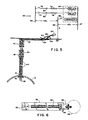
- Figure 1 is an elevational view of a convection blower assembly according to the invention, comprising a circular motor housing 10 having a small circular opening 12 that reveals two terminals 14 of a vertically mounted fractional horsepower motor 20 (Figure 3).
- the motor housing 10 is made of glazed porcelain for easy cleaning.
- the lower end of the housing 10 is flat so that it may rest on the flat floor of a conventional electric oven, and the lower portion of the housing has an overall diameter of about 10.16 cms (four inches) so that it may be positioned between the curved sections of a lower or baking element of the oven.
- the sides of the housing 10 extend vertically upward approximately 3 cms (1.2 inches) to a horizontal circular plate 16 having an outside diameter of about 19 cms (7.5 inches).
- An upper portion 18 of the motor housing extends up from the lower portion of the housing 10 to substantially enclose the motor 20 to protect it from dirt and grease vapors that may be circulated by the blower.
- a rotatable shaft 22 of the motor 20 extends through an axial hole in the top end surface of the upper portion 18 and is attached to the center of a centrifugal vane blower 24.
- the blower 24 comprises a flat circular disc divided into twelve peripheral sectors, the end portions of which bend downward to form vanes 26 the inner edges of what are slightly spaced from the outer surface of the upper motor housing 18, and the outer edges of which are similarly spaced from the inner surface of a cylindrical blower housing 28.
- the blower housing 28 is also formed of glazed porcelain and is generally cylindrical with an enclosed top 30. The lower peripheral edge of the blower housing 28 meshes with the upper peripheral edge of the motor housing plate 16 to form an enclosed blower cage, and is readily removable from the motor housing for ease in cleaning.
- the side wall of the blower housing 28 contains a plurality of windows 32 which, because of the relative thickness of the porcelain walls, are preferably slanted at various angles as shown in the sectional plan view of Figure 2 to direct the hot air being exhausted into various non-radial directions.
- windows 32 which, because of the relative thickness of the porcelain walls, are preferably slanted at various angles as shown in the sectional plan view of Figure 2 to direct the hot air being exhausted into various non-radial directions.
- one or more windows, such as window 34 may have a slanted sill to direct the air into an upward direction.
- the floor of the blower housing is the horizontal portion of the motor housing upper plate 16 and is formed with a plurality of holes 36 as shown in the bottom plan view of Figure 4.
- the vanes draw hot air in through the holes 36 and exhaust it in various directions through the blower housing windows 32.
- the motor 20 and associated circuitry can operate at oven temperatures up to about 560°F and must be removed from self-cleaning ovens before being subjected to those elevated temperatures.
- the conductive strip clipped to the oven and its attached female connector and wires coupled into the oven circuitry can withstand temperatures up to about 1100° and should not be removed.
- the blower unit may be easily removed by disconnecting the male wire connector 40 illustrated in Figure 5 as will subsequently be described. While so removed from the oven, the convection blower assembly may be easily disassembled and, after removal of the motor, may be placed in a conventional dishwasher for cleaning.
- the blower housing 28 is lifted from its floor, the vane blower is removed from the motor shaft by removing the nut 38 and removing the blower from the motor shaft, the upper motor housing 18 is then lifted from the lower housing 10, and the motor is then removed together with electrical wire, the wire guard spring 44, and the porcelian wire connector 40. All elements are immersible for cleaning except the motor which, during operation, is contained within the lower housing 10 and upper housing 18 and not within the normal flow of oven dirt and greases.
- FIG. 5 illustrates a typical 230 volt residential oven circuit and the connection thereto of the 110 volt convection blower. Illustrated in section in Figure 5 is a portion of the lower motor housing 10 having therein the round electrical connector hole 12 shown in Figure 1, and a wire pair 42 leading from the motor power terminals 14 to the male connector 40.
- a wire guard spring 44 with a large diameter end 46 looped behind the connector hole 12 interconnects the motor housing 10 with an annular groove 48 in the connector 40.
- the pins in the male wire connectors 40 engage corresponding terminals in a porcelain female connector 50.
- One of the terminals in the connector is connected directly to a resilient electrically conductive strips 52, the edge of which is illustrated in Figure 5 and which is shown in the plan view of Figure 6.
- An insulated wire 54 is connected to the second terminal in the connector 50 and exits through a small hole in the connectors side wall and into a raised wire retaining "tunnel" extending lengthwise through the strip 52 and to a point at which the resilient strip is curved around in a reverse direction to form an oven wall retaining clip 55.
- the clip 55 on the conductive strip 50 is inserted into one of heating element terminal passage holes 56 in the oven rear wall 58 and then drawn back so that the clip 55 engages the metallic wall which, together with all exposed metal parts of an oven, is at electrical ground or neutral.
- the clip is provided with a plurality of sharp points 59 through its conductive metal for piercing any coating in the rear wall. The points 59 should be positioned and properly aligned to permit easy installation of the clip and resist removal from the oven wall 58.
- FIG. 5 Illustrated in Figure 5 is a diagram of a typical electrical oven circuit 62.
- a thermostat circuit 64 normally operates at 110-120 volts and includes a thermostat control potentiometer or switch 66 for selecting a desired oven temperature.
- the thermostat employs a temperature-measuring thermocouple within the oven and closes a relay to energise a heating element whenever the measured oven temperature falls below the selected temperature.
- the thermostat relay is connected between a first leg 67 of a 230 volt power source and one end of the oven bake element 72 and broil element 78.
- the second end of the bake element is connected through an oven selector switch 70 to the second leg 69 of the 230 volt source.
- the two selector switches are usually included in a single manual rotary control which may further include a "pre-heat" position that closes both selector switches 70, 74 to energise both the bake and broil elements.
- a potential of 115 volts is between the ground or neutral conductor 68 and either of the legs 67, 69.
- the end of the insulated wire 54 to the convection blower is preferably provided with a conventional spade connector 60 which may be coupled to a divider or Y-spade connector to be installed between one of the spade connector ends of an oven element and its lead-in wire equipped with a female spade connector or screw fastener.
- the connector is inserted between one leg of a 230 volt source at an oven element and the neutral or grounded oven wall, so that the convection blower has only 115 volts applied thereto.
- the spade connector 60 may be connected to either wide of either oven element to pick up the 115 volt power.
- the spade connector 60 should be attached to the end of the bake element 72 at the position 80 in the oven circuitry. If the bake element is not readily available, attachment may be made in the broil circuit by attaching the spade connector 60 and a Y-connector at the point 82.
Landscapes
- Engineering & Computer Science (AREA)
- Chemical & Material Sciences (AREA)
- Combustion & Propulsion (AREA)
- Mechanical Engineering (AREA)
- General Engineering & Computer Science (AREA)
- Structures Of Non-Positive Displacement Pumps (AREA)
- Control Of Resistance Heating (AREA)
Applications Claiming Priority (2)
| Application Number | Priority Date | Filing Date | Title |
|---|---|---|---|
| US06/812,353 US4687908A (en) | 1985-12-23 | 1985-12-23 | Convection blower for conventional electric ovens |
| US812353 | 1985-12-23 |
Publications (2)
| Publication Number | Publication Date |
|---|---|
| EP0228892A2 true EP0228892A2 (de) | 1987-07-15 |
| EP0228892A3 EP0228892A3 (de) | 1988-10-19 |
Family
ID=25209328
Family Applications (1)
| Application Number | Title | Priority Date | Filing Date |
|---|---|---|---|
| EP86310040A Ceased EP0228892A3 (de) | 1985-12-23 | 1986-12-22 | Gebläse |
Country Status (5)
| Country | Link |
|---|---|
| US (1) | US4687908A (de) |
| EP (1) | EP0228892A3 (de) |
| JP (1) | JPS62234888A (de) |
| AU (1) | AU6673486A (de) |
| CA (1) | CA1262466A (de) |
Cited By (1)
| Publication number | Priority date | Publication date | Assignee | Title |
|---|---|---|---|---|
| EP3040626A1 (de) * | 2014-12-31 | 2016-07-06 | BSH Hausgeräte GmbH | Haushaltgerät mit einem erdungselement und einem elektrischen funktionselement |
Families Citing this family (13)
| Publication number | Priority date | Publication date | Assignee | Title |
|---|---|---|---|---|
| US4771163A (en) * | 1987-06-15 | 1988-09-13 | Brute Kitchen Equipment Company Inc. | Baking oven |
| USD306064S (en) | 1988-03-11 | 1990-02-13 | Zephyr Convection Cooking Systems Co. | Convection blower or similar article for use in an electric oven |
| EP0358344B1 (de) * | 1988-09-09 | 1994-03-30 | Microwave Ovens Limited | Mikrowellenöfen |
| DE3838447A1 (de) * | 1988-11-12 | 1990-05-17 | Standard Elektrik Lorenz Ag | Umluftgeblaese fuer backoefen |
| US5337654A (en) * | 1992-04-29 | 1994-08-16 | Northland Aluminum Products, Inc. | Portable oven air circulator |
| US5235962A (en) * | 1992-09-08 | 1993-08-17 | Maytag Corporation | Forced circulation oven door |
| US5756970A (en) * | 1995-05-03 | 1998-05-26 | Whirlpool Corporation | Thermal convection oven conversion algorithm |
| CA2181842C (en) * | 1995-08-07 | 2007-03-06 | James R. Barger | Oven preheat countdown timer |
| US6076516A (en) * | 1999-03-25 | 2000-06-20 | Tucker; Iler D. | Portable oven air circulating device |
| US6198076B1 (en) | 1999-11-17 | 2001-03-06 | National Presto Industries, Inc. | Convection oven |
| US6388235B1 (en) | 2001-10-30 | 2002-05-14 | Maytag Corporation | Convection cooking appliance with rapid preheat system |
| KR20050098989A (ko) * | 2004-04-08 | 2005-10-12 | 삼성전자주식회사 | 전자렌지 |
| US11346369B2 (en) * | 2017-10-23 | 2022-05-31 | Regal Beloit America, Inc. | Blower assembly and methods of assembling the same |
Family Cites Families (8)
| Publication number | Priority date | Publication date | Assignee | Title |
|---|---|---|---|---|
| US594206A (en) * | 1897-11-23 | John jeffreys | ||
| US2142842A (en) * | 1937-11-09 | 1939-01-03 | B F Sturtevant Co | Fan |
| US2652193A (en) * | 1947-10-25 | 1953-09-15 | Emerson Electric Mfg Co | Ventilating fan |
| US2694157A (en) * | 1950-11-15 | 1954-11-09 | Surface Combustion Corp | Hot fan for heat-treating furnaces |
| US2774293A (en) * | 1953-03-27 | 1956-12-18 | Louis J Jenn | Roof exhauster |
| US3246690A (en) * | 1958-11-05 | 1966-04-19 | Gen Motors Corp | Air cooled broiler |
| US4369760A (en) * | 1980-09-22 | 1983-01-25 | Northland Aluminum Products, Inc. | Portable oven air circulator |
| US4561416A (en) * | 1983-04-13 | 1985-12-31 | The Associates Group Partners | Self-contained portable oven air circulator |
-
1985
- 1985-12-23 US US06/812,353 patent/US4687908A/en not_active Expired - Fee Related
-
1986
- 1986-12-18 AU AU66734/86A patent/AU6673486A/en not_active Abandoned
- 1986-12-22 CA CA000525999A patent/CA1262466A/en not_active Expired
- 1986-12-22 EP EP86310040A patent/EP0228892A3/de not_active Ceased
- 1986-12-23 JP JP61307551A patent/JPS62234888A/ja active Pending
Cited By (1)
| Publication number | Priority date | Publication date | Assignee | Title |
|---|---|---|---|---|
| EP3040626A1 (de) * | 2014-12-31 | 2016-07-06 | BSH Hausgeräte GmbH | Haushaltgerät mit einem erdungselement und einem elektrischen funktionselement |
Also Published As
| Publication number | Publication date |
|---|---|
| AU6673486A (en) | 1987-06-25 |
| CA1262466A (en) | 1989-10-24 |
| JPS62234888A (ja) | 1987-10-15 |
| US4687908A (en) | 1987-08-18 |
| EP0228892A3 (de) | 1988-10-19 |
Similar Documents
| Publication | Publication Date | Title |
|---|---|---|
| US4687908A (en) | Convection blower for conventional electric ovens | |
| CA1056681A (en) | Range with convertible radiant convection oven | |
| US3393295A (en) | Cooking device with proportioning control | |
| US2523796A (en) | Portable roaster and broiler | |
| CN100579431C (zh) | 旋转烤肉箱和罩子 | |
| US3632983A (en) | Smooth surfaced, heated cooktop | |
| US3781757A (en) | Grounding clip for plug-in surface heating unit | |
| US20020060215A1 (en) | Cooking oven | |
| US4028520A (en) | Air flow system for common cavity microwave oven | |
| CA2153815A1 (en) | Thermal blend convection oven | |
| EP4094644A1 (de) | Korb mit abnehmbarer abdeckplatte für eine luftfritteuse und luftfritteuse mit korb mit abnehmbarer abdeckplatte | |
| EP1083773A2 (de) | Elektrischer Wärmestrahler in einem Mikrowellenofen | |
| EP1201998B1 (de) | Backröhre | |
| US3336465A (en) | Domestic oven with self-cleaning bottom wall | |
| CN211299602U (zh) | 一种电烤炉 | |
| US3566075A (en) | Cooking device with proportioning control | |
| EP0176223A3 (de) | Kühlungseinrichtung für elektrische Kochherde | |
| EP0951203A3 (de) | Anordnung mit Backofen und Kochfeld | |
| CN211212722U (zh) | 一种空气炸锅 | |
| CN223438373U (zh) | 一种高效空气炸锅 | |
| CN222828472U (zh) | 一种便于清洗的烤箱 | |
| CN215723391U (zh) | 一种电磁烹饪器具 | |
| CN222722855U (zh) | 空气炸锅 | |
| CN220494855U (zh) | 空气炸锅 | |
| CN218978664U (zh) | 一种空气烤箱 |
Legal Events
| Date | Code | Title | Description |
|---|---|---|---|
| PUAI | Public reference made under article 153(3) epc to a published international application that has entered the european phase |
Free format text: ORIGINAL CODE: 0009012 |
|
| AK | Designated contracting states |
Kind code of ref document: A2 Designated state(s): AT BE CH DE ES FR GB GR IT LI LU NL SE |
|
| RAP1 | Party data changed (applicant data changed or rights of an application transferred) |
Owner name: PARALLEL INDUSTRIES, INC. |
|
| RAP3 | Party data changed (applicant data changed or rights of an application transferred) |
Owner name: ZEPHYR CONVECTION COOKING SYSTEMS COMPANY |
|
| RAP3 | Party data changed (applicant data changed or rights of an application transferred) |
Owner name: ZEPHYR CONVECTION COOKING SYSTEMS COMPANY |
|
| PUAL | Search report despatched |
Free format text: ORIGINAL CODE: 0009013 |
|
| AK | Designated contracting states |
Kind code of ref document: A3 Designated state(s): AT BE CH DE ES FR GB GR IT LI LU NL SE |
|
| 17P | Request for examination filed |
Effective date: 19890331 |
|
| 17Q | First examination report despatched |
Effective date: 19891004 |
|
| STAA | Information on the status of an ep patent application or granted ep patent |
Free format text: STATUS: THE APPLICATION HAS BEEN REFUSED |
|
| 18R | Application refused |
Effective date: 19901229 |
|
| RIN1 | Information on inventor provided before grant (corrected) |
Inventor name: THORNE, KENNETH W. |