EP0228901A2 - Appareil de transfert de pastilles - Google Patents
Appareil de transfert de pastilles Download PDFInfo
- Publication number
- EP0228901A2 EP0228901A2 EP86310090A EP86310090A EP0228901A2 EP 0228901 A2 EP0228901 A2 EP 0228901A2 EP 86310090 A EP86310090 A EP 86310090A EP 86310090 A EP86310090 A EP 86310090A EP 0228901 A2 EP0228901 A2 EP 0228901A2
- Authority
- EP
- European Patent Office
- Prior art keywords
- wafer
- wafers
- cradle
- processing
- cassette
- Prior art date
- Legal status (The legal status is an assumption and is not a legal conclusion. Google has not performed a legal analysis and makes no representation as to the accuracy of the status listed.)
- Withdrawn
Links
Images


Classifications
-
- H—ELECTRICITY
- H10—SEMICONDUCTOR DEVICES; ELECTRIC SOLID-STATE DEVICES NOT OTHERWISE PROVIDED FOR
- H10P—GENERIC PROCESSES OR APPARATUS FOR THE MANUFACTURE OR TREATMENT OF DEVICES COVERED BY CLASS H10
- H10P72/00—Handling or holding of wafers, substrates or devices during manufacture or treatment thereof
- H10P72/30—Handling or holding of wafers, substrates or devices during manufacture or treatment thereof for conveying, e.g. between different workstations
- H10P72/34—Handling or holding of wafers, substrates or devices during manufacture or treatment thereof for conveying, e.g. between different workstations the wafers being stored in a carrier, involving loading and unloading
- H10P72/3411—Handling or holding of wafers, substrates or devices during manufacture or treatment thereof for conveying, e.g. between different workstations the wafers being stored in a carrier, involving loading and unloading involving loading and unloading of wafers
- H10P72/3412—Batch transfer of wafers
-
- H—ELECTRICITY
- H01—ELECTRIC ELEMENTS
- H01J—ELECTRIC DISCHARGE TUBES OR DISCHARGE LAMPS
- H01J37/00—Discharge tubes with provision for introducing objects or material to be exposed to the discharge, e.g. for the purpose of examination or processing thereof
- H01J37/30—Electron-beam or ion-beam tubes for localised treatment of objects
- H01J37/317—Electron-beam or ion-beam tubes for localised treatment of objects for changing properties of the objects or for applying thin layers thereon, e.g. for ion implantation
- H01J37/3171—Electron-beam or ion-beam tubes for localised treatment of objects for changing properties of the objects or for applying thin layers thereon, e.g. for ion implantation for ion implantation
-
- H—ELECTRICITY
- H10—SEMICONDUCTOR DEVICES; ELECTRIC SOLID-STATE DEVICES NOT OTHERWISE PROVIDED FOR
- H10P—GENERIC PROCESSES OR APPARATUS FOR THE MANUFACTURE OR TREATMENT OF DEVICES COVERED BY CLASS H10
- H10P72/00—Handling or holding of wafers, substrates or devices during manufacture or treatment thereof
- H10P72/30—Handling or holding of wafers, substrates or devices during manufacture or treatment thereof for conveying, e.g. between different workstations
- H10P72/36—Handling or holding of wafers, substrates or devices during manufacture or treatment thereof for conveying, e.g. between different workstations using air tracks
- H10P72/3604—Handling or holding of wafers, substrates or devices during manufacture or treatment thereof for conveying, e.g. between different workstations using air tracks the workpieces being stored in a carrier, involving loading and unloading
Definitions
- This invention relates to apparatus for the manufacture of electronic semiconductor devices and in particular to apparatus for automatically transferring semiconductor wafers between a processing station in an evacuated chamber and a storage cassette located outside the chamber.
- Electronic semiconductor devices such as integrated circuits are manufactured in large quantities on silicon wafers up to 200mm in diameter, each wafer comprising up to 1000 individual microcircuits which undergo processing simultaneously.
- Many of the processes used such as molecular team epitaxy, ion implantation, ion or electron beam lithography, plasma etching, sputter coating, etc, involve treatment of the wafer in an evacuated chamber, so that the need arises to transfer wafers between the standard cassettes in which they are stored and a processing station in the chamber.
- the wafers are very fragile and are easily damaged due to their thinness (usually less than 1.0mm) and their highly polished surfaces, and consequently the procedures used for their handling during the manufacturing processes are very important if large numbers of reject microcircuits are to be avoided.
- This is conventionally achieved by ensuring good contact between the wafer and a cooled support which may also involve gas or liquid cooling and necessitate a vacuum tight seal between the wafer and the support. Consequently, complicated clip or clamp means are necessary to hold the wafer in position and the presence of these further complicates the loading apparatus.
- the wafer processing temperature is typically several hundred °C
- it has been possible to utilize radiation cooling of the wafers in place of conduction cooling Consequently, the wafer counting means in each processing station can be simplified because it is no longer necessary to ensure good thermal contact between the wafer and its support, and advantage of this can be taken to simplify the loading apparatus.
- the invention provides apparatus for transferring wafers from at least one storage cassette to a plurality of processing stations in an evacuated chamber wherein each said station is arranged to receive a single wafer and to retain it in position during processing thereof, said apparatus comprising:-
- the wafer transfer apparatus of the invention will be located in a wafer processing apparatus, for example an ion implantation device.
- the invention provides a wafer processing apparatus, for example an ion implanter, plasma etcher or sputter coater, comprising:-
- the wafer pick-up means conveniently is adapted for location beneath a cassette in the vacuum lock and is provided with drive means capable of moving it and the wafers picked up by it through a vacuum isolating valve into the evacuated processsing chamber to a position at which the wafers may be deposited in the wafer transporting cradle.
- the wafer processing apparatus of the invention preferably includes at least one wafer carrying member disposed in the processing chamber, said carrying member comprising a plurality of processing stations and being provided, at each said processing station, with at least one stop member and at least two elongated wafer support members, each said support member being provided with a slot arranged to receive the lower portion of a wafer disposed therein substantially parallel to the plane of said carrying member, and each said stop member being arranged for contact with the upper portion of a wafer disposed in said support members whereby to prevent out-of-plane motion thereof towards said carrying member.
- An important application of the wafer transfer apparatus of the invention is the loading of wafers into an ion implanter, plasma etcher or sputter coater,which is capable of processing a large number of wafers simultaneously.
- the wafers are supported on the inside of a large rotating drum.
- the wafer carrying member typically supporting 3 wafers one above the other, may then comprise a flat rectangular plate fitted on the inside cylindrical surface of the drum. A plurality of such plates are fitted to complete the inner surface.
- a batch of 3 wafers is loaded by one cycle of the drive means on the first of the plates.
- the drum is then advanced to bring the next plate into the loading position and the process repeated with another batch of 3 wafers. In this way the process of loading the wafers is speeded up in comparison with the prior art apparatus in which each wafer is loaded individually.
- a hole slightly smaller in diameter than the wafer, may be provided in the wafer carrying member at each processing station, ensuring good radiative heat transfer from the rear of the wafer through the hole to a temperature controlled heat sink outside the rotating drum.
- the stop members and support members are preferably circular in cross section and are disposed around the circumference of the hole at each processing station.
- the wafer carrying member, stop members and support members are preferably fabricated from quartz (for the reasons described in our British patent application No. 8523441, filed 23 Sept.1985 and in the corresponding European Patent Application No.86307273.2, a copy of which is on the file of the present application).
- quartz for the reasons described in our British patent application No. 8523441, filed 23 Sept.1985 and in the corresponding European Patent Application No.86307273.2, a copy of which is on the file of the present application.
- the storage cassette is situated in a vacuum lock connected to the evacuated processing chamber by a vacuum isolating valve and provided with a vacuum tight entrance door.
- the apparatus is provided with a conveyor means for said cassette(s), said conveyor means being operable to align a first plurality of wafers in said cassette over said pick-up means, and being further operable, subsequent to the transfer of a said plurality of wafers to said cradle, to align a second plurality of wafers in said cassette over said pick-up means, and so on until all said wafers have been loaded into said processing stations.
- the conveyor means is conveniently mounted from the entrance door so that it is withdrawn from the lock when the door is removed, facilitating loading the cassettes.
- the conveyor means extends into the lock to enable the cassettes to be indexed over the wafer pick-up means.
- the lock should preferably be large enough to take several cassettes simultaneously.
- the lock chamber is evacuated.
- the isolating valve to the processing chamber is then opened, and the first cassette indexed over the wafer pick-up means, which is then used to lift the first batch of wafers through the isolating valve and deposit them in the wafer transporting cradle.
- the wafer pick-up means is then retracted below the cassettes, which are advanced by the conveyor means to index the second batch of wafers over the wafer pick-up means.
- the drive means loads the first batch of wafers into the processing stations, and returns the cradle to its starting position. The process is repeated until all the wafers have been loaded into the processing stations, after which the isolating valve is closed and the processing is commenced. After completion of processing, the valve is opened and the wafers returned to their original cassettes by reversing the steps described.
- isolating valve and wafer pick-up means conveniently is automated and controlled by a digital computer.
- the conveyor means for the cassettes is inclined upwardly into the vacuum lock (typically at 3° to the horizontal) so that the wafers rest against one side of their locating grooves in the cassettes whilst they are being moved. This minimizes relative movement of the wafers and the cassettes which may otherwise result in physical damage to the wafers.
- Any suitable conveyor means may be employed, but a particularly suitable type comprises a sliding carriage on which the cassettes are placed which is driven by linear motion motor enclosed within a tube sealed from the evacuated lock chamber. A suitable mechanism is described later.
- the wafer pick-up means may conveniently comprise a shoe capable of passing between the sides of the cassette and containing a plurality of grooves each adapted to receive the edge of one of said wafers and to support it in a substantially vertical orientation.
- the grooves are spaced apart by a distance equal to the spacing of the wafers in the cassette, so that the wafer pick-up means may lift the first plurality of wafers simultaneously as it is driven upwards through the cassette.
- the wafer transporting cradle may conveniently comprise second and third shoes spaced apart to allow the shoe of the wafer pick-up means to pass between them, said second and third shoes being adapted to support a plurality of wafers in substantially vertical orientations at points just below their horizontal diameter, each of said second and third shoes further comprising a plurality of grooves each adapted to receive the edge of one of said wafers.
- the spacing of the grooves is made equal to the spacing of the wafers in the cassettes, and the shoes are preferably adapted to carry the same number of wafers as the wafer pick-up means.
- the pick-up means lifts the first (or a subsequent) plurality of wafers from a cassette by a substantially vertical upward motion, until they are completely clear of the cassette.
- the pick-up means is then displaced substantially horizontally, and then lowered so that the shoe of the wafer pick-up means passes between the shoes of the cradle in such a way that the grooves in all the shoes are substantially in alignment, thereby transferring the wafers from the pick-up means to the cradle.
- the horizontal displacement of the pick-up means is conveniently obtained by slightly tilting the actuating rod which lifts the pick-up means so that the shoe is displaced in a substantially horizontal plane.
- the cradle is attached to a drive means, located within the evacuated processing chamber, which is used to transfer the wafers to the processing stations.
- a drive means located within the evacuated processing chamber, which is used to transfer the wafers to the processing stations.
- a variety of robot drive devices can be used, dependent on the relative positions of the loading point for the cradle in the processing chamber and the processing stations.
- the drive means may then conveniently comprise a cradle connecting arm linking the cradle to a linear motion guiding means adapted to confine the motion of the cradle to a single substantially vertical axis, and a crank member having a proximal end about which it is capable of pivoting and a distal end on which the guiding means is mounted, said crank member being adapted to move the guiding means clear of the processing stations to allow the cradle to be elevated on the guiding means to a point above the uppermost processing station, and subsequently to return the guiding means to its original position to permit the cradle to be lowered through each of said transfer locations in turn.
- the crank member is first turned to move the guiding means and cradle clear of the processing stations, permitting the cradle to be elevated along the guiding means.
- the crank member is then turned back to its original position in which the wafers in the cradle are situated in the planes they will occupy in the processing stations, and the loading is completed by lowering the cradle past the stations.
- At least some of the processing stations are disposed one above another in such a way that a wafer located in one of them is spaced farther from the carrying member than the wafer in the station above it.
- This may be achieved for example by having the wafer contact face of the stop members and the wafer receiving grooves in the support members successively further away from the body of the wafer carrying member for successively lower processing stations.
- the drive means may then be arranged to position the cradle above the uppermost processing station and to subsequently lower it through each of the wafer transferring locations in turn.
- Each of these transferring locations is preferably in horizontal alignment with the processing station into which the wafer in the transferring location is about to be loaded.
- the guiding means conveniently comprises a rod member and a tube member, both substantially vertically disposed, mounted at the distal end of the crank member.
- the cradle connecting arm is slidably mounted on the rod and tube members so that its motion is confined to an axis parallel to both, and rotation is prevented.
- the tube member is non-magnetic and comprises a lead screw along its axis.
- a nut means in threaded engagement with the lead screw is also provided within the tube member, and means are also provided to prevent the nut rotating.
- a first magnet means also within the tube member, is attached to the nut means.
- Second magnet means are provided exterior to the tube member and attached to a slide member which is free to slide on the exterior of the tube member.
- the cradle connectlng arm is attached to the slide member.
- the first and second magnet means act in magnetic co-operation with each other so that the slide and arm are caused to follow the motion of the nut means as it is driven up and down the tube by the leadscrew. Full details of a drive mechanism of this type are given in UK patent 1,317,105.
- Rotary motion is transmitted to the lead screw by a toothed belt drive from a shaft concentric with the pivot at the proximal end of the crank member.
- the crank member is hollow, completely enclosing the toothed belt drive, and forming a sealed enclosure connected with the inside of the tube member.
- a conventional ferrofluidic seal may be used to seal the crank pivot where it passes through the wall of the processing chamber, so that the inside of the crank member and tube member, containing the moving parts of the robot drive means, remains at atmospheric pressure, and any wear particles formed are excluded from the processing chamber.
- Conventional servo drive motors located outside the vacuum systems, may be used to provide the motion of the crank and guiding means.
- Similar magnetically coupled linear motion drives may also be used to provide the vertical motion required by the wafer pick-up means, and the horizontal motion required by the conveyor means.
- the limited tilting motion of the pick-up means required to locate the wafers above the transporting cradle is conveniently provided by tilting the drive motor and pick-up means with an electromagnetic actuator.
- the locating means comprises at least two wheels disposed one on each side of the cradle, ie, one on each of the second and third shoes.
- the wheels are spaced apart so that they will pass either side of a wafer located in one of the processing stations. They are further disposed so that when the cradle is located at the uppermost processing station with the wheels in contact with the carrying member, each of the wafers in the cradle is substantially in vertical alignment with the slots in the support members associated with the processing station into which it is about to be loaded.
- the wafers are then loaded simply by causing the cradle to descend through each transferring location in turn with the wheels in contact with the carrying member, whereby each wafer is located in turn in the grooves of the support members of the appropriate processing station.
- Control of the entire wafer transfer apparatus is preferably achieved by means of a suitably programmed digital computer using conventional techniques.
- Position sensing devices for example limit switches or photoelectric sensors, may be provided to give control signals indicative of the exact position of the various components and improve the precision of the operation.
- FIG 1 which illustrates the principal components of a preferred embodiment of the wafer transfer apparatus
- storage cassettes l, 2, and 3 are moved along the direction of arrow 4 by a conveyor means (not shown), until the first batch of wafers (typically three) is positioned over the wafer pick-up means 5.
- the cassettes and conveyor means are located in a vacuum lock.
- Wafer pick-up means 5 is then elevated along the direction of arrow 6 so that the first pick-up shoe 7 lifts the first batch of three wafers 8 from the cassette and carries them into the processing chamber.
- a wafer transporting cradle generally indicated by 9 and comprising second and third shoes 10 and 11 connected by means of 'U' shaped leaf springs 33 to bracket 93 attached to cradle supporting arm 12 on robot drive means 13, is positioned in the processing chamber slightly below the position of the fully elevated pick-up shoe 7 and displaced from it along an axis perpendicular to the planes of wafers 8.
- Wafer pick-up means 5 is then tilted slightly as indicated by arrow 14 so that wafers 8 are aligned with the grooves in shoes 10 and 11, and the pick-up means 5 is then lowered, leaving wafers 8 supported in shoes 10 and 11.
- Figure 1 shows the wafers being located in shoes 10 and 11 as pick-up shoe 7 on pick-up means 5 is descending.
- Pick-up means 5 is then further retracted below the base of cassette 3 in preparation for the lifting of the next batch of wafers.
- each of the shoes 7,10 and 11 contains a plurality of grooves 96, each groove adapted to receive the edge of one of the wafers and support it in a substantially vertical orientation.
- Shoe 7 is adapted to support a batch of wafers on its own, as shown in figure 1, whilst shoes 10 and 11 support a wafer between them at points just below their horizontal diameter.
- Drive means 13 comprises a linear motion guiding means 15 mounted on a crank member 16 which in turn is mounted in pivot 17.
- Guiding means 15 comprises tube member 18, a rod member 19 and a slide member 20 to which cradle connecting arm 12 is connected.
- Tube member 18 contains a drive motor (described below), and rod member 19 prevents slide member 20 from rotating.
- Slide member 20 is free to slide on members 18 and 19 in the direction of arrow 21, whilst crank member 16 pivots on pivot 17 in the direction of arrow 22.
- Pivot 17 is mounted from the wall of the processing chamber, and is positioned so that wafers 8 in transporting cradle 9 are aligned with the planes they will occupy in processing stations 23, 24 and 25 after they have been loaded.
- crank member 16 is turned until cradle 9 is clear of wafer carrying member 26 which has processing stations 23, 24 and 25. Slide member 20 is then raised to the top of tube member 18 and rod member 19, and the crank member 16 is then turned back to its original position. Wafers 8 will now be situated directly above the processing stations 23 - 25. Stop members 27, 29, and 31 and wafer support members 28, 30, and 32, are provided at each station, adapted so that the wafers are held in planes spaced at different distances from wafer support member 26, with the wafer in station 25 being spaced farther from member 26, and the distance between the planes being equal to the spacing of the wafers in cradle 9.
- the wafer transferring locations are coincident with the positions which the wafers occupy when in the processing stations 23, 24, and 25, so that reference numerals 23, 24 and 25 also identify the transferring locations.
- the wafer locating means preferably comprises two wheels 34, perpendicular to the planes of wafers 8 and mounted with their axles horizontal,on each of shoes 10 and 11, as shown in figure 1.
- these wheels comprise vacuum compatible ball races. More than one wheel may be provided on at least one of the shoes, disposed one above the other as explained below.
- member 20 is then lowered so that wheels 34 contact carrying member 26 and accurately align wafers 8 with the planes of processing stations 23 - 25, whilst springs 33 compensate for any misalignment.
- more than one wheel may be provided on each shoe to ensure that the wafers remain exactly parallel to carrying member 26 during this phase of the loading.
- wafer holding means 27 and 28 the stop and support members respectively of processing station 23, engage the first of wafers 8 and locate it in station 23, and subsequently holding means 29 and 30 engage the second wafer and locate it in station 24.
- the third wafer is engaged by holding means 31 and 32 in station 25.
- Wafers are unloaded by reversing the sequence of operation.
- Cradle 9 is first positioned below stations 23 - 25 and then raised with wheels 34 contacting member 26 so that wafers in stations 25, 24 and 23 are collected in turn by cradle 9.
- Crank member 16 is then rotated so that the cradle can be lowered, and then rotated back to the position shown in figure 1.
- Wafer pick-up means 5 is then raised to lift the wafers from the cradle, tilted clear of the cradle and lowered back to deposit the wafers in their positions in the cassette.
- evacuated processing chamber 35 contains a rotating drum 36 on the sides of which are mounted a plurality of wafer carrying members 26.
- Drum 36 is supported by bearing 37 which incorporates a ferrofluidic seal and is driven by motor 53.
- Vacuum lock 38 evacuated by pump means 95, is connected to process chamber 35 via vacuum isolating valve 39 operated by actuator motor 40. Access to vacuum lock 38 is gained through vacuum tight entrance door 41.
- Carriages 43-45 are driven by conveyor means 46 which is attached to door 41 and supported inside lock 38 by support 42.
- Conveyor means 46 is upwardly inclined in lock 38 to minimize rattle of the wafers in the cassettes.
- Any suitable type of conveyor mechanism can be used for cassettes 1 - 3 providing that it is capable of indexing them accurately over the wafer pick-up means, but preferably carriages 43 - 45 are slidably mounted on two rod-like members and motion is provided by at least one magnetically coupled linear motion actuator (described below) which is driven by actuator motor 47. This may be contained in one of the rod-like members used to guide the carriages. In this way, very few moving parts are present in the vacuum system and the generation of particulate contamination is minimized.
- Appropriate position sensors (not shown), conveniently photoelectric devices, may also be used to provide feedback to the conveyor control system (part of loader controller 48) to ensure accurate positioning of the cassettes.
- the wafer pick-up shoe 7, supported on wafer pick-up means 5, is driven by a second magnetically coupled linear motion actuator 49 which in turn is driven by motor 52 through a flexible coupling.
- the tilting motion of pick-up means 5 is conveniently provided by mounting actuator 49 on pivot 50 and connecting another point on actuator 49 to a small travel linear actuator 92, typically bellows sealed.
- pick-up means 5 is located to lift wafers through isolating valve 39 into the processing chamber to a point immediately beneath the processing stations 23-25 on one of wafer carrying members 26 mounted inside drum 36.
- Pivot 17 is driven by dual actuator motor 51 which also provides motive power for linear guiding means l5 (figure 1) through a shaft concentric with pivot 17. Motion may be transmitted from this shaft to the magnetically coupled actuator in tube member 18 by means of a toothed belt drive enclosed in a crank member 16, which is constructed in the form of a sealed hollow enclosure, but other methods are also suitable.
- Bearing 54 is positioned so that cradle 9 on the end of arm 12 can be positioned underneath the processing stations, as described.
- processing chamber 35 is maintained evacuated at all times using pump means 94.
- isolating valve 39 is closed by motor 40 and entrance door 41 is removed, withdrawing conveyor means 46 complete with carriages 43-45 from lock 38.
- Storage cassettes 1-3 are then loaded on to carriages 43-45 respectively, and conveyor means 46 and door 41 are replaced. Sufficient cassettes and carriages are provided to load all processing stations on drum 36, although only four are illustrated in figure 2 for simplicity.
- Lock 38 is then evacuated, after which valve 39 is opened.
- the first wafer carrying member 26 to be loaded is indexed into alignment with wafer pick-up means 5 by rotation of drum 36 by motor 53 and the first batch of wafers in cassette 3 are indexed over the pick-up means 5 by conveyor means 46 and motor 47.
- Linear actuator 49 and motor 52 then lift these wafers above cradle 9, and subsequently load them into the cradle as described , with the tilting motion of pick-up means 5 provided by bellows sealed actuator 92, as described.
- drum 36 is moved to align the next wafer carrying member with the pick-up means, and the whole cycle repeated.
- valve 39 is closed and the processing started. Wafers are unloaded and returned to their places in the cassettes after completion of the process by aligning the last of wafer carrying members 26 to be loaded with pick-up means 5, opening valve 39, and reversing the loading sequence, after which valve 39 is again closed.
- the cassettes are then unloaded by removing door 41 and conveyor means 46.
- Loading controller 48 is used to control the sequence of operation of the entire loading and unloading process and provides control signals for each of the motors and actuators.
- controller 48 comprises a suitably programmed digital computer.
- Various sensors eg limit switches and photoelectric devices, are provided to indicate ⁇ he positions of the various components and ensure that they are properly positioned.
- a shaft position encoder is provided on the drive shaft of drum 36 to provide a signal indicative of the angular rotation of the shaft so that the position of a particular wafer carrying member 26 in relation to pick-up means 5 is known. The provision of all such sensing devices on a mechanism of this type is conventional and need not be described.
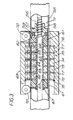
- Figure 3 shows a cross section through part of a linear motion actuator suitable for use in the invention in conveyor means 46 and actuator 49. It is based on the magnetic coupling principle explained in UK patent 1,317,105, but the piston and fluid drive system of the prior patent is replaced by a leadscrew and nut drive.
- Non-magnetic guide tube 55 contains a leadscrew 56 supported in suitable bearings at each end of the tube (not shown).
- the thread of leadscrew 56 is adapted to drive nut means 57 through balls 58, comprising a conventional low friction ball and nut drive.
- Nut 57 is connected to magnet carriage 60 by means of flexible coupling 59, which is located inside tube 55 by means of bearing bushes 61 (typically PTFE).
- the flexible coupling 59 prevents jamming of carriage 60 due to misalignment of tube 55 and leadscrew 56.
- a first magnet means comprising five ring shaped permanent magnets 62 - 66 is clamped around magnet carriage 60 by washer and circlip 67. These magnets are separated by ferromagnetic spacers, typically of mild steel (some of which are shown at 68), and are orientated with the poles as shown in the figure.
- Guide wire 71 runs the length of tube 55 and is threaded through holes in bushes 62, preventing rotation of nut means 57 as leadscrew 56 rotates.
- External carriage 69 runs on the exterior of tube 55 on vacuum compatible ball races 70. Three pairs of races are provided disposed at 120° to each other.
- a second magnet means comprising five ring shaped magnets 72 - 76, orientated as shown and separated by ferromagnetic spacers 77, are provided inside external carriage 69 and secured by circlip 78. As magnet carriage 60 is moved inside tube 55 by leadscrew 56, carriage 69 will follow it on the exterior on tube 55, by virtue of the interaction between the two sets of magnets 62-66 and 72-76, as explained in UK patent 1,317,105.
- tube 55 of figure 3 becomes tube member 18 and external carriage 69 becomes sliding member 20.
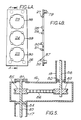
- the upper end of the tube 18 is closed with a flat disc, and the lower end is joined in a vacuum tight manner to the upper surface of hollow crank member 16, as shown in figure 5.
- Leadscrew 56 carries pulley 82 and runs in a ball race 80 disposed at the lower end of tube 18.
- a drive shaft 83, concentric with pivot 17, runs on ball races 81 and 84 and carries pulley 85, as shown.
- Pulleys 82 and 85 are adapted for use with a non-slip drive such as toothed belt 86.
- pivot 17 is mounted in bearing 54 (figure 2) which incorporates a ferrofluidic seal.
- Dual actuator motor 51 provides power for rotating both pivot 17 and shaft 83, and the interior of pivot 17, crank member 16 and tube member 18 are maintained at atmospheric pressure, thereby simplifying lubrication and preventing wear particles from moving parts entering processing chamber 35.
- Figures 4A and 4B show two elevations of a wafer carrying member for the wafer processing apparatus.
- Figure 4B is a cross section viewed along the arrows A - A in figure 4A.
- a plurality of carrying members 26 are disposed around the circumference of drum 36 in an overlapping fashion.
- Mounting posts 79 are used to support the members inside drum 36.
- Three processing stations 23-25 are provided. Wafers are supported in slots 87 in the elongated lower support members 28, 30 and 32, which are cylindrical pillars disposed as shown.
- Members 28, 30 and 32 are different lengths, as shown in figure 4B, so that the wafer in station 23 is closest to carrying member 26, and that in station 25 is farthest from it.
- the spacing in the horizontal plane between the wafers is equal to the spacing of the grooves in shoes 10 and 11, as explained.
- Upper stop members 27, 29 and 31 are also provided, disposed as shown. The length of these is selected so that each wafer is maintained parallel to member 26 when pressed against the stop member. During the processing, drum 36 is rotated and centrifugal force causes the wafers to be pressed against the stop members, so that they are maintained firmly in the desired position.
- the wafer carrying member 26, the lower support members 28, 30 and 32 and the upper stop members 27, 29 and 31 are all made of quartz, as explained in our British patent application 8523441, filed Sept. 23, 1985 referred to above.
- the large holes 88-90, at each processing station, allow efficient radiative heat transfer between the wafers and temperature controlled heat sink 91 (figure 2), permitting temperature control of the wafer during implantation.
- a batch of 84 125 mm diameter wafers can be automatically loaded into the implanter in less than 20 minutes, including the time required to evacuate vacuum load lock 38, which is a small fraction of a typical implant time for this number of wafers.
Landscapes
- Chemical & Material Sciences (AREA)
- Analytical Chemistry (AREA)
- Container, Conveyance, Adherence, Positioning, Of Wafer (AREA)
- Physical Vapour Deposition (AREA)
- Specific Conveyance Elements (AREA)
Applications Claiming Priority (2)
| Application Number | Priority Date | Filing Date | Title |
|---|---|---|---|
| GB858531723A GB8531723D0 (en) | 1985-12-24 | 1985-12-24 | Wafer transfer apparatus |
| GB8531723 | 1985-12-24 |
Publications (2)
| Publication Number | Publication Date |
|---|---|
| EP0228901A2 true EP0228901A2 (fr) | 1987-07-15 |
| EP0228901A3 EP0228901A3 (fr) | 1989-01-18 |
Family
ID=10590236
Family Applications (1)
| Application Number | Title | Priority Date | Filing Date |
|---|---|---|---|
| EP86310090A Withdrawn EP0228901A3 (fr) | 1985-12-24 | 1986-12-23 | Appareil de transfert de pastilles |
Country Status (3)
| Country | Link |
|---|---|
| EP (1) | EP0228901A3 (fr) |
| JP (1) | JPS62171138A (fr) |
| GB (1) | GB8531723D0 (fr) |
Cited By (4)
| Publication number | Priority date | Publication date | Assignee | Title |
|---|---|---|---|---|
| DE19541236A1 (de) * | 1995-11-06 | 1997-05-07 | Leybold Ag | Vorrichtung zum Beschichten der Oberflächen von als Rotationskörper ausgeformten Substraten |
| CN103268850A (zh) * | 2013-05-03 | 2013-08-28 | 中国电子科技集团公司第四十八研究所 | 一种太阳能电池片离子注入机 |
| CN103426625A (zh) * | 2013-07-19 | 2013-12-04 | 青岛云路新能源科技有限公司 | 自动码片机 |
| CN114144870A (zh) * | 2019-06-26 | 2022-03-04 | 德国艾托特克公司 | 将物品移动到处理站的装置和方法、输送系统和处理设备 |
Family Cites Families (2)
| Publication number | Priority date | Publication date | Assignee | Title |
|---|---|---|---|---|
| US4311427A (en) * | 1979-12-21 | 1982-01-19 | Varian Associates, Inc. | Wafer transfer system |
| US4498833A (en) * | 1982-05-24 | 1985-02-12 | Varian Associates, Inc. | Wafer orientation system |
-
1985
- 1985-12-24 GB GB858531723A patent/GB8531723D0/en active Pending
-
1986
- 1986-12-23 EP EP86310090A patent/EP0228901A3/fr not_active Withdrawn
- 1986-12-24 JP JP61316043A patent/JPS62171138A/ja active Pending
Cited By (6)
| Publication number | Priority date | Publication date | Assignee | Title |
|---|---|---|---|---|
| DE19541236A1 (de) * | 1995-11-06 | 1997-05-07 | Leybold Ag | Vorrichtung zum Beschichten der Oberflächen von als Rotationskörper ausgeformten Substraten |
| CN103268850A (zh) * | 2013-05-03 | 2013-08-28 | 中国电子科技集团公司第四十八研究所 | 一种太阳能电池片离子注入机 |
| CN103268850B (zh) * | 2013-05-03 | 2015-09-02 | 中国电子科技集团公司第四十八研究所 | 一种太阳能电池片离子注入机 |
| CN103426625A (zh) * | 2013-07-19 | 2013-12-04 | 青岛云路新能源科技有限公司 | 自动码片机 |
| CN103426625B (zh) * | 2013-07-19 | 2016-02-10 | 青岛云路新能源科技有限公司 | 自动码片机 |
| CN114144870A (zh) * | 2019-06-26 | 2022-03-04 | 德国艾托特克公司 | 将物品移动到处理站的装置和方法、输送系统和处理设备 |
Also Published As
| Publication number | Publication date |
|---|---|
| GB8531723D0 (en) | 1986-02-05 |
| EP0228901A3 (fr) | 1989-01-18 |
| JPS62171138A (ja) | 1987-07-28 |
Similar Documents
| Publication | Publication Date | Title |
|---|---|---|
| US4776744A (en) | Systems and methods for wafer handling in semiconductor process equipment | |
| US11894251B2 (en) | Transport system | |
| US4836733A (en) | Wafer transfer system | |
| US5280983A (en) | Semiconductor processing system with robotic autoloader and load lock | |
| US8293066B2 (en) | Apparatus and methods for transporting and processing substrates | |
| CN101548361B (zh) | 高产量串行晶片处理终端站 | |
| US6468353B1 (en) | Method and apparatus for improved substrate handling | |
| US6575737B1 (en) | Method and apparatus for improved substrate handling | |
| US6935828B2 (en) | Wafer load lock and magnetically coupled linear delivery system | |
| US9728436B2 (en) | Transfer mechanism with multiple wafer handling capability | |
| EP0848412A2 (fr) | Plate-forme d'extraction de plaquettes | |
| EP0189279A2 (fr) | Système de traitement de semi-conducteurs | |
| US6318957B1 (en) | Method for handling of wafers with minimal contact | |
| KR102629482B1 (ko) | 동시 기판 이송을 위한 로봇 | |
| WO2008070004A2 (fr) | Dispositif d'alignement d'encoches de galette de rendement élevé | |
| JPH0159352B2 (fr) | ||
| EP0244202A2 (fr) | Système de transfert de plaquette à semi-conducteur | |
| EP0244950B1 (fr) | Méthode et appareil de manipulation et de traitement de matériaux en forme de disque | |
| US20010041121A1 (en) | Single chamber vacuum processing tool | |
| JPS62171138A (ja) | ウエ−ハ移転装置 | |
| EP2187433B1 (fr) | Appareil et méthode de transport et de traitement de substrats | |
| JPH06334026A (ja) | オリエンテーションフラット合わせ機内蔵型ウエハ収納装置 | |
| CN101740439A (zh) | 用于传输和处理衬底的装置和方法 | |
| Komatsu et al. | A high throughput end station of a high current ion implanter |
Legal Events
| Date | Code | Title | Description |
|---|---|---|---|
| PUAI | Public reference made under article 153(3) epc to a published international application that has entered the european phase |
Free format text: ORIGINAL CODE: 0009012 |
|
| AK | Designated contracting states |
Kind code of ref document: A2 Designated state(s): CH DE FR GB LI NL |
|
| PUAL | Search report despatched |
Free format text: ORIGINAL CODE: 0009013 |
|
| RHK1 | Main classification (correction) |
Ipc: H01L 21/00 |
|
| AK | Designated contracting states |
Kind code of ref document: A3 Designated state(s): CH DE FR GB LI NL |
|
| STAA | Information on the status of an ep patent application or granted ep patent |
Free format text: STATUS: THE APPLICATION IS DEEMED TO BE WITHDRAWN |
|
| 18D | Application deemed to be withdrawn |
Effective date: 19890102 |
|
| RIN1 | Information on inventor provided before grant (corrected) |
Inventor name: COLLING, JOHN ANTHONY Inventor name: MOFFATT, STEPHEN Inventor name: STONESTREET, PAUL RICHARD |