EP0228964A1 - Elektromagnet mit konzentrischen Ringspulen - Google Patents
Elektromagnet mit konzentrischen Ringspulen Download PDFInfo
- Publication number
- EP0228964A1 EP0228964A1 EP86402884A EP86402884A EP0228964A1 EP 0228964 A1 EP0228964 A1 EP 0228964A1 EP 86402884 A EP86402884 A EP 86402884A EP 86402884 A EP86402884 A EP 86402884A EP 0228964 A1 EP0228964 A1 EP 0228964A1
- Authority
- EP
- European Patent Office
- Prior art keywords
- cylinder head
- face
- coils
- electromagnet
- yoke
- Prior art date
- Legal status (The legal status is an assumption and is not a legal conclusion. Google has not performed a legal analysis and makes no representation as to the accuracy of the status listed.)
- Granted
Links
- 238000004804 winding Methods 0.000 title abstract description 7
- 230000004907 flux Effects 0.000 claims abstract description 8
- 230000000295 complement effect Effects 0.000 claims abstract description 3
- 238000010030 laminating Methods 0.000 claims 1
- 230000001133 acceleration Effects 0.000 description 3
- 238000005516 engineering process Methods 0.000 description 3
- 230000006698 induction Effects 0.000 description 3
- 125000006850 spacer group Chemical group 0.000 description 3
- 239000000696 magnetic material Substances 0.000 description 2
- 230000002093 peripheral effect Effects 0.000 description 2
- 238000005266 casting Methods 0.000 description 1
- 239000004020 conductor Substances 0.000 description 1
- 230000008094 contradictory effect Effects 0.000 description 1
- 238000011156 evaluation Methods 0.000 description 1
- 238000003475 lamination Methods 0.000 description 1
- 239000000463 material Substances 0.000 description 1
- 230000035699 permeability Effects 0.000 description 1
- 238000009738 saturating Methods 0.000 description 1
- 230000003068 static effect Effects 0.000 description 1
Images

Classifications
-
- H—ELECTRICITY
- H01—ELECTRIC ELEMENTS
- H01F—MAGNETS; INDUCTANCES; TRANSFORMERS; SELECTION OF MATERIALS FOR THEIR MAGNETIC PROPERTIES
- H01F7/00—Magnets
- H01F7/06—Electromagnets; Actuators including electromagnets
- H01F7/08—Electromagnets; Actuators including electromagnets with armatures
Definitions
- the present invention relates to an electromagnet and more particularly to a fast electromagnet with concentric O-rings.
- the intrinsic power of an electromagnet is summed up by its ability to accelerate the mass of its moving part.
- a is the acceleration in ms2, F the force exerted in newtons, m the mass of the mobile part in Kg, ⁇ the density in Kg / m3 and V the volume of the mobile part in m3, we have: B being the Tesla induction, s the contact surface between the fixed part and the mobile part and ⁇ the relative permeability of the vacuum.
- B being the Tesla induction, s the contact surface between the fixed part and the mobile part and ⁇ the relative permeability of the vacuum.
- the electromagnet according to the invention is of the type in which the working faces of the two coils are substantially coplanar and in which the coils are arranged in housings of the yoke of a magnetic circuit whose movable non-laminated element is movable parallel to the axis of the coils, and the face of the cylinder head located on the side of the air gap having a frustoconical cavity, and the mobile element having on the air gap side a frustoconical face complementary to that of the cylinder head.
- the electromagnet according to the invention is characterized in that the face of the movable element opposite the air gap is preferably in the form of a stepped cavity so that the volumes of this element traversed by the magnetic flux have , for each coil, trapezoidal axial sections.
- the cylinder head can be laminated radially. This lamination can be achieved by stacking sheets cut according to n + 1 profiles for an electromagnet with n coils and arranged so as to optimize the expansion.
- the stack can comprise sheets having n slots, sheets having (n-1) slots and so on, sheets having a slot, and sheets not split, these various sheets being superposed so as to form n clean annular passages. to house the coils.
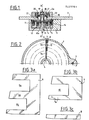
- the electromagnet according to the invention comprises a housing 1 which is fixed to a support 2 by screws 3 and has a central hub 4.
- a laminated cylinder head designated as a whole by the reference 5.
- This cylinder head is formed from the strips 6, 7 and 8 arranged radially side by side.
- the strips 6 have a section in E ( Figure 3a) and therefore have two slots 9a and 9b ; they extend between the hub 4 and the internal peripheral wall of the housing 1.
- the strips 7, each of which is adjacent to a strip 6, have a U-shaped section (FIG. 3 b ) and extend from the middle branch 6 of the strip 6 to the inner peripheral wall of the housing 1, their slots 10 thus being arranged facing the slots 9 b of the strips 6.
- the strips 8, each of which is adjacent to a strip 7 have an approximately rectangular section and extend in front of the inner branch 7a of the strip 7.
- Two concentric toroidal coils 11 and 12 connected to supply conductors 13 are arranged in the annular recesses formed by the succession of the different slots 9b -10 and 9a of the cylinder head 3, the whole being joined together by casting a material plastic, as indicated in 14.
- the coils 11 and 12 are produced by continuous winding of a strip and are wound in opposite directions.
- the outer face 5a of the cylinder head 5 is machined so as to form with the axis X-X of the electromagnet an angle preferably between 65 and 88 °.
- a movable axis 14 having a cylindrical surface 15a.
- a movable cup 16 is held in abutment on the bearing 15 ′ of the axis 15 and made integral with this axis by a spacer 17, a washer 18 and a nut 19.
- the spacer 17 is recalled by an elastic washer 20 taking support from 'on the one hand on the spacer 17 and on the other hand on a washer 21 housed in the support 2.
- a nut 22 concentric with the axis 15 is screwed on a cylindrical part 2a of the reminder 2.
- the cup 16 has a concave frusto-conical face 16a which is turned towards the cylinder head 5 and the part located opposite this cylinder head makes with the axis XX the same angle as the face 5a of said cylinder head 5.
- the opposite face 16 b is concave and of stepped shape so that the volumes of the cup traversed by the magnetic flux have for each coil, substantially trapezoidal axial sections and a height between 1 and 2.5 mm.
- the cup 16 has in its center a bore 23 allowing it to center on the axis 15 and a bore 24 allowing it to bear on the cylindrical part 15a.
Landscapes
- Physics & Mathematics (AREA)
- Electromagnetism (AREA)
- Engineering & Computer Science (AREA)
- Power Engineering (AREA)
- Electromagnets (AREA)
- Particle Accelerators (AREA)
Applications Claiming Priority (2)
| Application Number | Priority Date | Filing Date | Title |
|---|---|---|---|
| FR8519564A FR2592519B1 (fr) | 1985-12-30 | 1985-12-30 | Electro-aimant a bobines toriques concentriques |
| FR8519564 | 1985-12-30 |
Publications (2)
| Publication Number | Publication Date |
|---|---|
| EP0228964A1 true EP0228964A1 (de) | 1987-07-15 |
| EP0228964B1 EP0228964B1 (de) | 1990-11-07 |
Family
ID=9326422
Family Applications (1)
| Application Number | Title | Priority Date | Filing Date |
|---|---|---|---|
| EP19860402884 Expired - Lifetime EP0228964B1 (de) | 1985-12-30 | 1986-12-22 | Elektromagnet mit konzentrischen Ringspulen |
Country Status (4)
| Country | Link |
|---|---|
| EP (1) | EP0228964B1 (de) |
| JP (1) | JPS62241305A (de) |
| DE (1) | DE3675522D1 (de) |
| FR (1) | FR2592519B1 (de) |
Cited By (1)
| Publication number | Priority date | Publication date | Assignee | Title |
|---|---|---|---|---|
| FR2664087A1 (fr) * | 1990-05-17 | 1992-01-03 | Stiatti Vittorio | Electro-aimant pour soupapes electro-magnetiques. |
Families Citing this family (1)
| Publication number | Priority date | Publication date | Assignee | Title |
|---|---|---|---|---|
| CN104517716A (zh) * | 2014-09-15 | 2015-04-15 | 浙江鑫业电子科技有限公司 | 车用高速电磁铁的加工工艺 |
Citations (5)
| Publication number | Priority date | Publication date | Assignee | Title |
|---|---|---|---|---|
| DE261697C (de) * | ||||
| FR951952A (fr) * | 1947-08-09 | 1949-11-07 | électro-aimant perfectionné à deux armatures | |
| US3022449A (en) * | 1956-12-21 | 1962-02-20 | Cutler Hammer Inc | Alternating current electromagnetic device |
| DE2110982A1 (de) * | 1970-03-11 | 1971-09-30 | Johann Biber Jun | Elektromagnet |
| GB2098005A (en) * | 1981-05-05 | 1982-11-10 | Sulzer Ag | A double-acting electromagnet device for controlling the movement of an injector valve of a fuel injector |
-
1985
- 1985-12-30 FR FR8519564A patent/FR2592519B1/fr not_active Expired
-
1986
- 1986-12-22 EP EP19860402884 patent/EP0228964B1/de not_active Expired - Lifetime
- 1986-12-22 DE DE8686402884T patent/DE3675522D1/de not_active Expired - Fee Related
- 1986-12-27 JP JP31591286A patent/JPS62241305A/ja active Pending
Patent Citations (5)
| Publication number | Priority date | Publication date | Assignee | Title |
|---|---|---|---|---|
| DE261697C (de) * | ||||
| FR951952A (fr) * | 1947-08-09 | 1949-11-07 | électro-aimant perfectionné à deux armatures | |
| US3022449A (en) * | 1956-12-21 | 1962-02-20 | Cutler Hammer Inc | Alternating current electromagnetic device |
| DE2110982A1 (de) * | 1970-03-11 | 1971-09-30 | Johann Biber Jun | Elektromagnet |
| GB2098005A (en) * | 1981-05-05 | 1982-11-10 | Sulzer Ag | A double-acting electromagnet device for controlling the movement of an injector valve of a fuel injector |
Cited By (2)
| Publication number | Priority date | Publication date | Assignee | Title |
|---|---|---|---|---|
| FR2664087A1 (fr) * | 1990-05-17 | 1992-01-03 | Stiatti Vittorio | Electro-aimant pour soupapes electro-magnetiques. |
| GR910100210A (el) * | 1990-05-17 | 1992-07-30 | Vittorio Stiatti | Ηλεκτρομαγνητης για ηλεκτρομαγνητικες βαλβιδες. |
Also Published As
| Publication number | Publication date |
|---|---|
| DE3675522D1 (de) | 1990-12-13 |
| EP0228964B1 (de) | 1990-11-07 |
| FR2592519B1 (fr) | 1988-03-11 |
| JPS62241305A (ja) | 1987-10-22 |
| FR2592519A1 (fr) | 1987-07-03 |
Similar Documents
| Publication | Publication Date | Title |
|---|---|---|
| EP0974185B1 (de) | Verbesserter linearantrieb | |
| FR2682542A1 (fr) | Actionneur electromagnetique comportant une structure statorique a trois poles de longueurs differentes et distributeurs pneumatiques mettant en óoeuvre de tels actionneurs. | |
| EP0829129A1 (de) | Elektromagnetischen betätiger mit mindenstens zwei stabile stellungen durch magnetische verriegelung | |
| FR2986923A1 (fr) | Actionneur a entrainement direct compact generant une force constante | |
| EP3057201A1 (de) | Rotor eines elektromotors, und entsprechender elektromotor | |
| FR2583210A1 (fr) | Dispositif d'actionnement electromagnetique | |
| EP1521352B1 (de) | Aktive Schwingungsdämpfungsvorrichtung eines Schwingungselementes | |
| FR2705510A1 (fr) | Actionneur électromagnétique monophasé à faible course présentant un bon rapport force sur puissance électrique. | |
| FR2627030A1 (fr) | Rotor de machine electrique tournante a aimants permanents de type a concentration de flux | |
| EP2156538B1 (de) | Elektromagnetischer aktor mit variabler reluktanz | |
| EP0228964B1 (de) | Elektromagnet mit konzentrischen Ringspulen | |
| FR2574880A1 (fr) | Systeme formant butee magnetique axiale pour machine tournante | |
| CH643680A5 (fr) | Electro-aimant pour frein. | |
| EP0034955B1 (de) | Zündspule für Verbrennungsmotoren | |
| FR2838186A1 (fr) | Dispositif de capteur magnetique de position angulaire | |
| EP3602758A1 (de) | Lineares stellglied mit zwei unabhängigen beweglichen massen und optimierter konfiguration von permanentmagneten | |
| WO2004061875A2 (fr) | Actionneur electromagnetique de soupape a aimant permanent | |
| EP1955339B1 (de) | Elektromagnetischer auslöser mit dauermagneten, die v-förmig angeordnet werden | |
| EP0644346A1 (de) | Gebogener oder gerader Magnetstab aus getrennten Magneten | |
| EP1237394A1 (de) | Magnetkreisanordnung für elektrodynamischen Lautsprecher | |
| WO1992008238A1 (fr) | Procede de fabrication d'un actionneur electromagnetique et actionneur ainsi realise | |
| EP2534851B1 (de) | Magnetischer elektrodynamischer wandlermotor | |
| WO2003090237A1 (fr) | Actionneur electromagnetique a aimant permanent | |
| EP1121748A1 (de) | Magnetischer drehaktuator | |
| FR2810153A1 (fr) | Actionneur electromagnetique notamment de soupape de moteur a combustion interne |
Legal Events
| Date | Code | Title | Description |
|---|---|---|---|
| PUAI | Public reference made under article 153(3) epc to a published international application that has entered the european phase |
Free format text: ORIGINAL CODE: 0009012 |
|
| AK | Designated contracting states |
Kind code of ref document: A1 Designated state(s): DE GB IT |
|
| 17P | Request for examination filed |
Effective date: 19870527 |
|
| 17Q | First examination report despatched |
Effective date: 19900409 |
|
| GRAA | (expected) grant |
Free format text: ORIGINAL CODE: 0009210 |
|
| AK | Designated contracting states |
Kind code of ref document: B1 Designated state(s): DE GB IT |
|
| ITF | It: translation for a ep patent filed | ||
| GBT | Gb: translation of ep patent filed (gb section 77(6)(a)/1977) | ||
| REF | Corresponds to: |
Ref document number: 3675522 Country of ref document: DE Date of ref document: 19901213 |
|
| PLBE | No opposition filed within time limit |
Free format text: ORIGINAL CODE: 0009261 |
|
| STAA | Information on the status of an ep patent application or granted ep patent |
Free format text: STATUS: NO OPPOSITION FILED WITHIN TIME LIMIT |
|
| 26N | No opposition filed | ||
| ITTA | It: last paid annual fee | ||
| PGFP | Annual fee paid to national office [announced via postgrant information from national office to epo] |
Ref country code: GB Payment date: 19921214 Year of fee payment: 7 |
|
| PGFP | Annual fee paid to national office [announced via postgrant information from national office to epo] |
Ref country code: DE Payment date: 19930126 Year of fee payment: 7 |
|
| PG25 | Lapsed in a contracting state [announced via postgrant information from national office to epo] |
Ref country code: GB Effective date: 19931222 |
|
| GBPC | Gb: european patent ceased through non-payment of renewal fee |
Effective date: 19931222 |
|
| PG25 | Lapsed in a contracting state [announced via postgrant information from national office to epo] |
Ref country code: DE Effective date: 19940901 |
|
| PG25 | Lapsed in a contracting state [announced via postgrant information from national office to epo] |
Ref country code: IT Free format text: LAPSE BECAUSE OF NON-PAYMENT OF DUE FEES;WARNING: LAPSES OF ITALIAN PATENTS WITH EFFECTIVE DATE BEFORE 2007 MAY HAVE OCCURRED AT ANY TIME BEFORE 2007. THE CORRECT EFFECTIVE DATE MAY BE DIFFERENT FROM THE ONE RECORDED. Effective date: 20051222 |