EP0228997B1 - Automatische Vorrichtung zum Aufwickeln eines langgestreckten Gutes - Google Patents
Automatische Vorrichtung zum Aufwickeln eines langgestreckten Gutes Download PDFInfo
- Publication number
- EP0228997B1 EP0228997B1 EP86810598A EP86810598A EP0228997B1 EP 0228997 B1 EP0228997 B1 EP 0228997B1 EP 86810598 A EP86810598 A EP 86810598A EP 86810598 A EP86810598 A EP 86810598A EP 0228997 B1 EP0228997 B1 EP 0228997B1
- Authority
- EP
- European Patent Office
- Prior art keywords
- drum
- barrel
- axis
- gripping
- cutting
- Prior art date
- Legal status (The legal status is an assumption and is not a legal conclusion. Google has not performed a legal analysis and makes no representation as to the accuracy of the status listed.)
- Expired - Lifetime
Links
Images



Classifications
-
- B—PERFORMING OPERATIONS; TRANSPORTING
- B65—CONVEYING; PACKING; STORING; HANDLING THIN OR FILAMENTARY MATERIAL
- B65H—HANDLING THIN OR FILAMENTARY MATERIAL, e.g. SHEETS, WEBS, CABLES
- B65H65/00—Securing material to cores or formers
-
- B—PERFORMING OPERATIONS; TRANSPORTING
- B65—CONVEYING; PACKING; STORING; HANDLING THIN OR FILAMENTARY MATERIAL
- B65H—HANDLING THIN OR FILAMENTARY MATERIAL, e.g. SHEETS, WEBS, CABLES
- B65H67/00—Replacing or removing cores, receptacles, or completed packages at paying-out, winding, or depositing stations
- B65H67/04—Arrangements for removing completed take-up packages and or replacing by cores, formers, or empty receptacles at winding or depositing stations; Transferring material between adjacent full and empty take-up elements
- B65H67/044—Continuous winding apparatus for winding on two or more winding heads in succession
- B65H67/048—Continuous winding apparatus for winding on two or more winding heads in succession having winding heads arranged on rotary capstan head
-
- B—PERFORMING OPERATIONS; TRANSPORTING
- B65—CONVEYING; PACKING; STORING; HANDLING THIN OR FILAMENTARY MATERIAL
- B65H—HANDLING THIN OR FILAMENTARY MATERIAL, e.g. SHEETS, WEBS, CABLES
- B65H2701/00—Handled material; Storage means
- B65H2701/30—Handled filamentary material
- B65H2701/33—Hollow or hose-like material
Definitions
- the present invention relates to an automatic reel of an elongated product intended to form torches, comprising two permutable winding drums and cutting and fixing means capable of cutting the elongated product during each permutation and of fixing the free end of this product to a drum at each cutting operation.
- Automatic winders are used to wind various elongated products which open continuously from a production line. It can be electrical cables, but also plastic profiles or tubes having a circular profile or another shape.
- the reels generally have two drums designed either to receive coils or to directly support the winding when it comes to forming torches. By working alternately on one drum and on the other, it is possible to interpose certain operations on the winding which is finished, while continuing the winding of the product on the other drum.
- various means are already known which make it possible to automatically pass the elongated product from one drum to another when a coil or a torch is finished.
- Patent GB-A-1074 709, American patent US 3,704,839, German patent DE 821,666 or Swiss patent CH 582106 for example describe devices of this kind.
- the object of the present invention is to provide a solution to this problem by means of a device which does not require any adjustment whatever the section of the product which it is desired to wind.
- each drum carries a cutting and pinching device actuated by a control member.
- the reel shown schematically in Figs. 1 to 2 is arranged so as to form, from a plastic tube 1 which leaves a production line, torches which can be harvested alternately on each of the two drums 2 and 3 which the reel comprises.
- These two drums pivot at the two ends of an arm 4 which constitutes the frame of the barrel and which is itself supported in the middle of its length by a shaft end 5 in a fixed frame 6 containing the bearing of the shaft 5, means for driving the barrel 4 in rotation and various accessories which are not important here.
- the operation of the reel is as follows: the free end of the product 1 is fixed to the reel drum which is in position 3 and while this drum is rotated, the product 1 is guided by a slicing device 7 so as to form layers of successive turns on the drum 3.
- the barrel 4 rotates clockwise in FIG. 1 by 180 ° and the drum 2 which is empty takes the place of the drum 3.
- the product 1 is sectioned on the empty drum and fixed to this drum by a clamping device while a binding machine 8 disposed in the vicinity of the drum which is in position 2 comes into action to bind the torch formed on this drum, which allows the unloading of the torch.
- the drum in position 3 continues to rotate, so that a new torch is formed on its barrel.
- each drum has two flanges 9 and 10 and between these flanges a barrel 11, but as will be seen later, the flanges and the barrel of each drum are divided into segments or sectors distributed circumferentially around the axis of the drum, and the sectors which constitute the flange 10 are pivotably mounted so as to assume a position oriented parallel to the axis of the drum as shown in 10 ⁇ in FIG. 2.
- the torch formed on the barrel 11 is accessible and can be easily discharged.
- Figs. 3, 4 and 5 we will describe in more detail the constitution of one of the drums 2 and 3, and more precisely of the cutting and pinching device that each of these drums comprises.
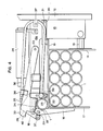
- Fig. 3 is a partial elevation view in the direction of the arrow A in FIG. 1 showing part of a drum whose axis (not shown) is located at the top of the drawing with a horizontal orientation.
- a star 12 which is integral with the shaft connecting the drum to the barrel 4.
- This star has a certain number of radial grooves converging towards the axis of rotation of the drum and which each serve to fix and guide a base 13 whose position can therefore be adjusted in the radial direction which allows to vary the diameter of the drum barrel and therefore to adapt it to torches of different dimensions.
- the number of plinths and therefore grooves formed in the star 12 can be for example six or eight, or if necessary four, depending on the embodiments.
- Each base 13 comprises means for guiding and clamping a flange sector 14 which is contained in a plane perpendicular to the axis of the drum and which is supported by a slide 15, so that each of the flange sectors 14 can be moved in the direction parallel to the axis of the drum, which makes it possible to fix its position and consequently to determine the width of the torch which will be formed on the drum.
- the base 13 has an axial extension 13a at the free end of which pivots a profiled arm 16 to which is fixed a foldable flange sector 17.
- This flange sector has the same shape and the same dimensions as the sector 14
- the arm 16 and the sector 17 together constitute a valve which can be folded down around a pivot axis 18 which extends in the circumferential direction at a distance from the axis of the drum which is determined by the position of the base 13.
- the base 13 also carries a barrel plate 19 which is constituted by a curved sheet. This sheet is fixed at one end to an arm 20 which pivots at 21 on the base 13.
- the arm 20 is linked by an articulated link 23 to a transmission and control mechanism.
- This transmission and control mechanism firstly comprises a jack, the cylinder 24 of which is fixed by its base to the base 13 in a position parallel to the axis of the drum.
- a movable rod 25 comes out of the cylinder 24 and at its free end it is articulated on a transmission lever 26 which pivots itself at 27 on the end of the axial extension 13a of the base 13.
- the lever 26 has as a triangular shape . In the vicinity of one of its peaks it is linked by the articulation 28 to the rod 25 of the jack, while in the vicinity of another vertex, opposite the articulation point 27 it is articulated by means of a link 29 on the arm 16 carrying the sector 17. It will be understood that an actuation of the jack 24 causing the rod 25 to move to the left in FIG.
- This knife blade 30 is a steel blade fixed in a radial plane containing the axis of the drum at the end of the extension of the base 13.
- This knife blade 30 has a profiled edge 31 arranged so as to facilitate cutting of the product 1.
- this knife is arranged in a radial position between the barrel 11 and the pivot axis of the valves. 17.
- the extension 13a carries a pinch lever 32 (fig. 4) which pivots around a hinge 33 on the extension 13a.
- this lever has a segment in the shape of a claw 34 which is kept pressed against the end of the product 1, housed under the barrel segment 19.
- the elements of the drum are recognized in FIG.
- the arm 16 of the valve 17 has between its articulation point 18 and the place where it is fixed to the sector 17 a notch 35 which constitutes a hooking member for the product 1.
- the pinch lever 32 is biased by an arguated hairpin spring 36 which is fixed by a stirrup 37 on the upper part of the base 13 and which itself carries at the end of one of its branches a stirrup 38 embracing the lever 32.
- the end of the other branch of the spring 36 is also engaged in a cylindrical opening which has a stud 39 pivotally mounted on the extension 13a of the base 13.
- the drum which is in position 2 remains stationary during the formation of a new torch on the drum which is in position 3, that is to say that the valves 17 remain in the open position and the clamping lever 32 remains in the raised position as seen in FIG. 5.
- the product is instantly sectioned and at the same time, as the roller 37 performs a downward movement in FIG. 5, it lets the pinch lever 32 move downward under the effect of the force of the spring 36 transmitted by the caliper 38.
- the initial segment of the new torch is therefore pinched against the internal face of the barrel segment 19 , so that the product 1 continues to be driven, but by the empty drum, and no longer by the full drum.
- the valve 17 can continue its stroke until the final position of its movement as shown in FIGS. 3 and 4.
- the product segment which is adjacent to part 42 passes between the barrel segment equipped with the cutting and nipping device and the segment next and go over part 19 of that segment.
- the pulling force which is exerted on the product 1 is transmitted to this product by the pinching lever 32 and to ensure the achievement of this effort, a bracket 43 is also provided on the extension 13a of the base 13 to hold the lever 32 in position.
- the device thus produced is capable of operating in a perfectly regular manner. It requires no adjustment whatever the section of the elongated product that one wishes to wind. The force required for gripping is given by the hairpin spring 36 and therefore the gripping force is greater the greater the section of the product.
- the operation of the device shown in the drawing has been explained by assuming that the elongated product 1 was a plastic tube, but it should be understood that this product could also be a cable, a flexible profile, a bar, or any other elongated product. capable of being packaged as a torch or coil.
Landscapes
- Replacement Of Web Rolls (AREA)
- Wire Processing (AREA)
Claims (10)
- Automatische Vorrichtung zum Aufwickeln eines langgestreckten Gutes, geeignet zum kontinuierlichen Bilden von Rollen aufeinanderfolgender Abschnitte des besagten Gutes, wobei wenigstens zwei um ihre Achse rotierbare Trommeln (2, 3) vorhanden sind, sowie mit Mittel (4, 5) zum Tragen der Trommeln, die zyklisch verschiebbar sind, um die Trommeln aufeinanderfolgend in eine Initialposition mitzunehmen, in welcher ein Endstück des langgestreckten Gutes (1) an der Trommel befestigt wird, wobei auf jeder Trommel eine Schneide- und Klemmvorrichtung (16, 32, 30) vorhanden ist, dadurch gekennzeichnet, dass die Schneide- und Klemmvorrichtung ein Messer (30) aufweist, welches gegenüber der Trommel unbeweglich ist, dass das Klemmittel (16, 32, 35, 34) beweglich ist und dass ein Betätigungsmittel (24) ebenfalls auf der Trommel angebracht ist, welches das Klemmittel verschiebt, wobei das Letztere das langgestreckte Gut verschiebt, um es zu schneiden und in die Klemmposition mitzunehmen.
- Automatische Aufwickelvorrichtung nach Anspruch 1, in welcher jede Trommel einen Kern (11) und zwei Scheiben (9, 10) aufweist, die dazu bestimmt sind, das Auflegen von windungen des langgestreckten Gutes auf den Kern zu begrenzen, wobei wenigstens eine dieser Scheiben in eine Anordnung von Klappen (16, 17) unterteilt ist, welche um Achsen, die umfangsweise um die Achse der Trommel verteilt sind, kippbar sind, dadurch gekennzeichnet, dass die Schneide- und Klemmvorrichtung auf jeder Trommel einer der Klappen zugeordnet ist und dass das besagte Betätigungsmittel (24) derart an der Klappe (16, 17) befestigt ist, dass es diese kippen kann zwischen einer offenen Position, in welcher das Herausnehmen der Rolle möglich ist und einer geschlossenen Position zur Führung des Produktes, wobei während des Kippens die Schneide- und Klemmvorrichtung betätigt wird.
- Aufwickelvorrichtung nach Anspruch 2, dadurch gekennzeichnet, dass das besagte Betätigungsmittel ein Druckzylinder ist, der parallel zur Achse der Trommel zwischen dem Kern und der besagten Achse angeordnet ist.
- Aufwickelvorrichtung nach Anspruch 2, dadurch gekennzeichnet, dass die Kippachsen der Klappen (16, 17) jeder Trommel auf einem Kreis angeordnet sind, welcher hinter dem Kern (11) zwischen dem Letzteren und der Achse der Trommel verläuft, dass das Messer (30) auf einer radialen Ebene zwischen dem Kern der Trommel und der Kippachse der Klappe angeordnet ist und dass der Kern eine Oeffnung aufweist, welche derart angeordnet ist, dass der Durchtritt des langgestreckten Gutes von aussen zum Inneren des Kernes möglich ist.
- Aufwickelvorrichtung nach Anspruch 4, dadurch gekennzeichnet, dass der Kern (11) jeder Trommel aus um die Achse der Trommel verteilten getrennten Segmenten (19) gebildet ist, die an ihrem einen Ende fliegend auf einem Tragstern (12) gelagert sind, der einen Teil der Trommel bildet, dass jedes Segment (19) des Kernes die zugehörige kippbare Klappe (16, 17) und ein Betätigungsmittel (24) trägt, wobei die besagte Oeffnung durch den Raum zwischen dem Segment (19), welches die Schneide- und Klemmvorrichtung (16, 32, 30) trägt, und einem der benachbarten Segmente gebildet ist.
- Aufwickelvorrichtung nach Anspruch 5, dadurch gekennzeichnet, dass die Schneide- und Klemmvorrichtung ein Mitnahmeorgan (16, 35) für das langgestreckte Gut aufweist, welches das langgestreckte Gut (1) im Augenblick der Betätigung in eine Richtung parallel zur Achse der Trommel derart verschiebt, dass es in das Innere des Kernes (11) eingreift und dass sie andererseits ein Klemmorgan (32, 34) aufweist, welches sich radial in einer Richtung zentrifugal gegenüber der Achse der Trommel verschiebt, um den Teil des langgestreckten Gutes, der sich an der Seite des Messers befindet, gegen die Innenseite des Kernes zu drücken.
- Aufwickelvorrichtung nach Anspruch 6, dadurch gekennzeichnet, dass das besagte Mitnahmeorgan (16, 35) ein Arm ist, der die kippende Klappe (17) trägt, und welcher sich während des Schneide- und Klemmvorganges verschiebt zwischen einer Position, in der die Klappe, welche er trägt, parallel zur Achse der Trommel ist, und einer Position, in der diese Klappe radial angeordnet ist, mit seiner Innenseite bündig mit dem freien Ende des Segmentes des Kernes.
- Aufwickelvorrichtung nach den Ansprüchen 3 und 7, dadurch gekennzeichnet, dass jede Schneide- und Klemmvorrichtung einen auf einem Sockel (13a) schwenkbaren Uebertragungshebel (26) aufweist, welcher Sockel ein Teil des-jenigen Kernsegmentes ist, welchem die Vorrichtung zugeordnet ist, dass jede Vorrichtung ausserdem ein Gelenk aufweist zwischen dem besagten Uebertragungshebel (26) und der Stange (25) des Betätigungszylinders, eine Schubstange (29) zwischen dem Uebertragungshebel (26) und dem Befestigungsorgan (16), eine auf den Uebertragungshebel derart montierte Walze (37), dass das Klemmorgan (32) gehalten wird, wobei das Letztere ebenfalls ein auf dem Sockel schwenkbarer Hebel ist, und eine Feder (36), welche den Klemmhebel (32) gegen die Halterolle (37) drückt.
- Aufwickelvorrichtung nach Anspruch 8, dadurch gekennzeichnet, dass der Uebertragungshebel (26) zusätzlich mit einer Kernplatte (19, 20) verbunden ist, welche schwenkbar auf dem Sockel (13a) derart angebracht ist, dass sie sich geringfügig gegen die Achse neigen kann, wenn die Klappe geöffnet wird.
- Aufwickelvorrichtung nach Anspruch 8, dadurch gekennzeichnet, dass die Feder (36) durch ein Haarnadelglied gebildet ist, deren einer Arm den Klemmhebel (32) belastet, und deren anderer Arm auf dem Sockel befestigt ist, damit der Klemmhebel (32) in den beiden Extrempositionen gegen die auf dem Uebertragungshebel (26) angebrachte Rolle (37) gedrückt wird, und damit der Klemmhebel in der Position bei geschlossener Klappe von der Feder derart belastet wird, dass er das langgestreckte Gut (1) klemmt.
Priority Applications (1)
| Application Number | Priority Date | Filing Date | Title |
|---|---|---|---|
| AT86810598T ATE64918T1 (de) | 1985-12-20 | 1986-12-17 | Automatische vorrichtung zum aufwickeln eines langgestreckten gutes. |
Applications Claiming Priority (2)
| Application Number | Priority Date | Filing Date | Title |
|---|---|---|---|
| CH5474/85 | 1985-12-20 | ||
| CH547485 | 1985-12-20 |
Publications (3)
| Publication Number | Publication Date |
|---|---|
| EP0228997A2 EP0228997A2 (de) | 1987-07-15 |
| EP0228997A3 EP0228997A3 (en) | 1988-07-06 |
| EP0228997B1 true EP0228997B1 (de) | 1991-07-03 |
Family
ID=4294206
Family Applications (1)
| Application Number | Title | Priority Date | Filing Date |
|---|---|---|---|
| EP86810598A Expired - Lifetime EP0228997B1 (de) | 1985-12-20 | 1986-12-17 | Automatische Vorrichtung zum Aufwickeln eines langgestreckten Gutes |
Country Status (3)
| Country | Link |
|---|---|
| EP (1) | EP0228997B1 (de) |
| AT (1) | ATE64918T1 (de) |
| DE (1) | DE3680085D1 (de) |
Families Citing this family (2)
| Publication number | Priority date | Publication date | Assignee | Title |
|---|---|---|---|---|
| CH681538A5 (de) * | 1989-11-02 | 1993-04-15 | Maillefer Nokia Holding | |
| CN112591557B (zh) * | 2020-12-04 | 2022-09-13 | 福德机器人(成都)有限责任公司 | 一种集卷料筒自动上料与头丝切割的复合机器人 |
Family Cites Families (8)
| Publication number | Priority date | Publication date | Assignee | Title |
|---|---|---|---|---|
| DE821666C (de) * | 1948-12-09 | 1951-11-19 | Siemens Ag | Aufwickelvorrichtung fuer die kontinuierliche Fertigung von elektrischen Leitungen |
| FR1311606A (fr) * | 1961-01-19 | 1962-12-07 | Appareil pour l'enroulement ou le bobinage de fils métalliques ou de câbles arrivant d'une machine à gainer ou similaire | |
| DE1247112B (de) * | 1963-10-01 | 1967-08-10 | Kurt Scheller | Vorrichtung zum fortlaufenden Aufwickeln von strangfoermigem Gut, insbesondere Draht, Kabel u. dgl. |
| US3704839A (en) * | 1970-12-30 | 1972-12-05 | Entwistle Co | Dual boxing coiler |
| CH582106A5 (en) * | 1974-07-23 | 1976-11-30 | Maillefer Sa | Twisting device for large dia. cables - having drawing and feed devices mounted on support moveable between winding up positions |
| FR2375128A1 (fr) * | 1976-12-21 | 1978-07-21 | Sute | Procede et dispositif automatique de mise en couronne pour tube souple |
| IT1158548B (it) * | 1982-12-06 | 1987-02-18 | Carlo Campetella | Macchina per avvolgere automaticamente ed in continuo tubi flessibili in ordinate matasse legate con fascette |
| AU2252083A (en) * | 1982-12-29 | 1984-07-05 | Grumman Aerospace Corporation | Wire coil production |
-
1986
- 1986-12-17 AT AT86810598T patent/ATE64918T1/de not_active IP Right Cessation
- 1986-12-17 EP EP86810598A patent/EP0228997B1/de not_active Expired - Lifetime
- 1986-12-17 DE DE8686810598T patent/DE3680085D1/de not_active Expired - Lifetime
Also Published As
| Publication number | Publication date |
|---|---|
| DE3680085D1 (de) | 1991-08-08 |
| EP0228997A2 (de) | 1987-07-15 |
| EP0228997A3 (en) | 1988-07-06 |
| ATE64918T1 (de) | 1991-07-15 |
Similar Documents
| Publication | Publication Date | Title |
|---|---|---|
| EP0419299B1 (de) | Wagen zum Abwickeln von einem Film zu einer Verpackungsmaschine | |
| EP0875476B1 (de) | Wickler mit zwei Spindeln zum Aufwickeln einer Bahn | |
| EP0475886B1 (de) | Vorrichtung und Verfahren zum Öffnen einer Papierrolle und zum Verbinden von dem Ende einer Papierbahn an das Ende einer anderen Papierbahn | |
| CH681538A5 (de) | ||
| EP0192904A1 (de) | Rundballenpresse mit Bindemechanismus | |
| EP0228997B1 (de) | Automatische Vorrichtung zum Aufwickeln eines langgestreckten Gutes | |
| FR2498979A1 (fr) | Procede de fabrication de longerons de pale d'helicoptere | |
| EP0015223A1 (de) | Vorrichtung zum Binden von Drahtspulen | |
| FR2567500A1 (fr) | Appareil de bobinage de materiau en bande | |
| EP0003385B1 (de) | Kontinuierlich arbeitende zweifache Wickelmaschine | |
| EP0113323A2 (de) | Automatische Maschine zum kontinuierlichen Aufwickeln von flexiblen Schläuchen zu geordneten, banderolierten Wickeln | |
| FR2573059A1 (fr) | Appareil de devidage de film d'emballage | |
| EP0030901A1 (de) | Maschine zur Herstellung flacher oder konischer scheibenförmiger Wicklungen für Elektromotoren | |
| EP0230398B1 (de) | Vorrichtung zum Binden eines Drahtbundes auf einer Aufwickeleinrichtung | |
| FR2499958A1 (fr) | Perfectionnements aux machines a enrouler des bandes de matiere en bobines | |
| EP0267157A2 (de) | Doppeldrahtaufspulmaschine mit drehbarem Spulenhalter | |
| FR2537556A1 (fr) | Machine automatique a bobiner les petits tores | |
| FR2598695A1 (fr) | Machine a decouper et a embobiner des feuilles de grande longueur et procede pour sa mise en oeuvre | |
| FR2940789A1 (fr) | Procede de mise en grappes de bulbes de plantes pourvus d'une tige et installation pour la mise en oeuvre de ce procede | |
| WO1989000145A1 (fr) | Procede et machine pour la fabrication de pelotes de fils textiles | |
| FR2661166A1 (fr) | Dispositif pour le pliage transversal d'une gaine souple continue. | |
| FR2661924A1 (fr) | Dispositif pour l'enroulement d'un fil sur le tambour d'un appareil servant a l'alimentation en fil des aiguilles d'une machine a tricoter. | |
| BE437756A (de) | ||
| FR2556520A1 (fr) | Appareil pour former des bobinages de stator de type ondule pour machines dynamo-electriques | |
| BE396611A (de) |
Legal Events
| Date | Code | Title | Description |
|---|---|---|---|
| PUAI | Public reference made under article 153(3) epc to a published international application that has entered the european phase |
Free format text: ORIGINAL CODE: 0009012 |
|
| AK | Designated contracting states |
Kind code of ref document: A2 Designated state(s): AT BE CH DE FR GB IT LI NL SE |
|
| PUAL | Search report despatched |
Free format text: ORIGINAL CODE: 0009013 |
|
| AK | Designated contracting states |
Kind code of ref document: A3 Designated state(s): AT BE CH DE FR GB IT LI NL SE |
|
| 17P | Request for examination filed |
Effective date: 19881229 |
|
| 17Q | First examination report despatched |
Effective date: 19900406 |
|
| GRAA | (expected) grant |
Free format text: ORIGINAL CODE: 0009210 |
|
| RAP1 | Party data changed (applicant data changed or rights of an application transferred) |
Owner name: NOKIA-MAILLEFER S.A. |
|
| AK | Designated contracting states |
Kind code of ref document: B1 Designated state(s): AT BE CH DE FR GB IT LI NL SE |
|
| REF | Corresponds to: |
Ref document number: 64918 Country of ref document: AT Date of ref document: 19910715 Kind code of ref document: T |
|
| REF | Corresponds to: |
Ref document number: 3680085 Country of ref document: DE Date of ref document: 19910808 |
|
| ITF | It: translation for a ep patent filed | ||
| GBT | Gb: translation of ep patent filed (gb section 77(6)(a)/1977) | ||
| PLBE | No opposition filed within time limit |
Free format text: ORIGINAL CODE: 0009261 |
|
| STAA | Information on the status of an ep patent application or granted ep patent |
Free format text: STATUS: NO OPPOSITION FILED WITHIN TIME LIMIT |
|
| 26N | No opposition filed | ||
| EAL | Se: european patent in force in sweden |
Ref document number: 86810598.2 |
|
| PGFP | Annual fee paid to national office [announced via postgrant information from national office to epo] |
Ref country code: NL Payment date: 19961126 Year of fee payment: 11 |
|
| PGFP | Annual fee paid to national office [announced via postgrant information from national office to epo] |
Ref country code: SE Payment date: 19961128 Year of fee payment: 11 |
|
| PGFP | Annual fee paid to national office [announced via postgrant information from national office to epo] |
Ref country code: BE Payment date: 19961129 Year of fee payment: 11 |
|
| PG25 | Lapsed in a contracting state [announced via postgrant information from national office to epo] |
Ref country code: SE Free format text: LAPSE BECAUSE OF NON-PAYMENT OF DUE FEES Effective date: 19971218 |
|
| PG25 | Lapsed in a contracting state [announced via postgrant information from national office to epo] |
Ref country code: BE Free format text: LAPSE BECAUSE OF NON-PAYMENT OF DUE FEES Effective date: 19971231 |
|
| BERE | Be: lapsed |
Owner name: S.A. NOKIA-MAILLEFER Effective date: 19971231 |
|
| PG25 | Lapsed in a contracting state [announced via postgrant information from national office to epo] |
Ref country code: NL Free format text: LAPSE BECAUSE OF NON-PAYMENT OF DUE FEES Effective date: 19980701 |
|
| NLV4 | Nl: lapsed or anulled due to non-payment of the annual fee |
Effective date: 19980701 |
|
| EUG | Se: european patent has lapsed |
Ref document number: 86810598.2 |
|
| PGFP | Annual fee paid to national office [announced via postgrant information from national office to epo] |
Ref country code: FR Payment date: 20011130 Year of fee payment: 16 |
|
| PGFP | Annual fee paid to national office [announced via postgrant information from national office to epo] |
Ref country code: CH Payment date: 20011203 Year of fee payment: 16 |
|
| PGFP | Annual fee paid to national office [announced via postgrant information from national office to epo] |
Ref country code: GB Payment date: 20011204 Year of fee payment: 16 Ref country code: DE Payment date: 20011204 Year of fee payment: 16 Ref country code: AT Payment date: 20011204 Year of fee payment: 16 |
|
| REG | Reference to a national code |
Ref country code: GB Ref legal event code: IF02 |
|
| PG25 | Lapsed in a contracting state [announced via postgrant information from national office to epo] |
Ref country code: GB Free format text: LAPSE BECAUSE OF NON-PAYMENT OF DUE FEES Effective date: 20021217 Ref country code: AT Free format text: LAPSE BECAUSE OF NON-PAYMENT OF DUE FEES Effective date: 20021217 |
|
| PG25 | Lapsed in a contracting state [announced via postgrant information from national office to epo] |
Ref country code: LI Free format text: LAPSE BECAUSE OF NON-PAYMENT OF DUE FEES Effective date: 20021231 Ref country code: CH Free format text: LAPSE BECAUSE OF NON-PAYMENT OF DUE FEES Effective date: 20021231 |
|
| PG25 | Lapsed in a contracting state [announced via postgrant information from national office to epo] |
Ref country code: DE Free format text: LAPSE BECAUSE OF NON-PAYMENT OF DUE FEES Effective date: 20030701 |
|
| GBPC | Gb: european patent ceased through non-payment of renewal fee |
Effective date: 20021217 |
|
| REG | Reference to a national code |
Ref country code: CH Ref legal event code: PL |
|
| PG25 | Lapsed in a contracting state [announced via postgrant information from national office to epo] |
Ref country code: FR Free format text: LAPSE BECAUSE OF NON-PAYMENT OF DUE FEES Effective date: 20030901 |
|
| REG | Reference to a national code |
Ref country code: FR Ref legal event code: ST |
|
| PG25 | Lapsed in a contracting state [announced via postgrant information from national office to epo] |
Ref country code: IT Free format text: LAPSE BECAUSE OF NON-PAYMENT OF DUE FEES;WARNING: LAPSES OF ITALIAN PATENTS WITH EFFECTIVE DATE BEFORE 2007 MAY HAVE OCCURRED AT ANY TIME BEFORE 2007. THE CORRECT EFFECTIVE DATE MAY BE DIFFERENT FROM THE ONE RECORDED. Effective date: 20051217 |