EP0229013A2 - Vorrichtung zur Schwingungsdämpfung für einen Schrittmotor - Google Patents
Vorrichtung zur Schwingungsdämpfung für einen Schrittmotor Download PDFInfo
- Publication number
- EP0229013A2 EP0229013A2 EP87100059A EP87100059A EP0229013A2 EP 0229013 A2 EP0229013 A2 EP 0229013A2 EP 87100059 A EP87100059 A EP 87100059A EP 87100059 A EP87100059 A EP 87100059A EP 0229013 A2 EP0229013 A2 EP 0229013A2
- Authority
- EP
- European Patent Office
- Prior art keywords
- pulse motor
- vibration damping
- damper
- damping apparatus
- vibration
- Prior art date
- Legal status (The legal status is an assumption and is not a legal conclusion. Google has not performed a legal analysis and makes no representation as to the accuracy of the status listed.)
- Withdrawn
Links
Images



Classifications
-
- H—ELECTRICITY
- H02—GENERATION; CONVERSION OR DISTRIBUTION OF ELECTRIC POWER
- H02K—DYNAMO-ELECTRIC MACHINES
- H02K5/00—Casings; Enclosures; Supports
- H02K5/24—Casings; Enclosures; Supports specially adapted for suppression or reduction of noise or vibrations
-
- H—ELECTRICITY
- H02—GENERATION; CONVERSION OR DISTRIBUTION OF ELECTRIC POWER
- H02K—DYNAMO-ELECTRIC MACHINES
- H02K37/00—Motors with rotor rotating step by step and without interrupter or commutator driven by the rotor, e.g. stepping motors
- H02K37/22—Damping units
-
- G—PHYSICS
- G11—INFORMATION STORAGE
- G11B—INFORMATION STORAGE BASED ON RELATIVE MOVEMENT BETWEEN RECORD CARRIER AND TRANSDUCER
- G11B21/00—Head arrangements not specific to the method of recording or reproducing
- G11B21/02—Driving or moving of heads
- G11B21/08—Track changing or selecting during transducing operation
Definitions
- the present invention relates to a vibration damping apparatus for damping vibrations produced in pulse motors such as linear pulse motors sand rotary pulse motors for intermittently driving and feeding a head of a floppy disk regeneration device and the like.
- Pulse motors can be positioned by closed loop control and hence widely employed for various types of driving mechanisms in office automation terminal apparatuses. For example, with the recent progress of office automation, floppy disk regenerative devices have prevailed as memories. The head of such a floppy disk regenerative device is frequently driven by a pulse motor. Moreover, pulse motors are employed for driving print heads of printers and typewriters, etc. These pulse motors however suffer from some problems. In particular, vibration produced in such a pulse motor causes severe problems for various applications. In the following, general arrangement of a pulse motor will first be described, before discussing the problems.
- Figs. 12 and 13 exemplarily show a prior pulse motor of this type.
- the movable member 1 has a comb-shaped movable tooth 1a formed on the lower surface thereof.
- the stator 2 includes a permanent magnet 3, a slit plate 4, an electromagnet coils 5, 5, a yoke 6, a linear bearings 7, 7, guides 8, 9, and a back plate 18.
- the slit plate 4 is disposed on the lower side of the movable member 1 in a confronting relation therewith.
- the yoke 6 around which the electromagnet coils 5, 5 are fixed, and the flat H-shaped permanent magnet 3 are fixedly mounted in or on the lower side of the slit plate 4.
- the yoke 6 has in the center thereof, a cross-shaped groove to thereby form four magnetic poles 6a, 6b, 6c, and 6d.
- the slit plate 4 has comb-shaped pole teeth 4a, 4b, 4c, and 4d formed at positions just above the magnetic poles 6a, 6b, 6c, and 6d. These pole teeth 4a, 4b, 4c, and 4d are positioned separated away from the movable tooth 1a of the movable member 1 with a very minute gap in a confronting relation therewith by holding the linear bearings 7, 7 between the slit plate 4 and the movable member 1.
- the guides 8, 9 are mounted on the upper side of the movable member 1.
- the linear bearings 7, 7 and the movable member 1 are fitted longitudinally movably in a travelling path formed by the slit plate 4 and the guides 8, 9.
- the back plate 18 is mounted on the lower side of the permanent magnet 3.
- the movable member 1 is mounted movably longitudinally thereof relatively to the stator 2.
- the movable tooth 1a and the pole teeth 4a, 4b, 4c, and 4d are adapted to oppose to each other with a minute gap. With a pulse-shaped current supplied to the coils 5, 5 in these stituation, the movable member 1 is moved stepwise on the stator 2.
- the movable member 1 is forced to vibrate longitudinally thereof for some time around a prescribed position even after it is moved to that position.
- a pulse motor does not need a conversion mechanism for converting a rotating motion to a linear motion are for example between it and an object to be driven since it undergoes the linear motion by itself, but this unfortunately causes the time needed to settle the movable member 1 to be prolonged since the vibration of the movable member 1 is not cancelled out by making use of mechanical loss of the conversion mechanism. Therefore, when the pulse motor is employed for driving the head of a floppy disk, the time to access data is delayed or the data so accessed presents insufficient reliability.
- a linear pulse motor is in general rotated followed by vibration since it is rotated stepwise by a prescribed angle (step angle) for each pulse input.
- such a motor can be regarded as a kind of spring from the viewpoint of the mechanism of producing the torque of the motor, and so the vibration of the motor is accelerated and amplified by stopped pulsating torque to result in further larger vibration.
- Fig. 14 is a cross sectional view illustrating prior arrangement of a vibration damping apparatus 57 with use of the frictional load and the inertia load in the mechanical method described above.
- designated at at 51 is a pulse motor, and 52 is a shaft thereof.
- a mild steel disk 53 having a mounting part 53 a is attached to the shaft 52 by means of a screw 64, which disk includes an annular frictional plate 55 bonded thereto.
- An annular inertia member 56 composed of a permanent magnet 56a and a back plate 6b is disposed on the other surface of the frictional plate 55 in contact therewith.
- This back plate 56b forms magnetic paths ⁇ , between the permanent magnet 56a and the mild steel disk 3 to serve as a flywheel for averaging variations in the rotating speed of the motor.
- These mild steel disk 53, frictional plate 55, and inertia member 56 together construct the vibration damping apparatus 57.
- the inertia member 6 and the mild steel disk 53 are integrally rotated owing to magnetic force of the permanent magnet 56a when the acceleration of the motor 51 is low.
- the inertia member 56 is left behind from the rotation of the shaft 52 because of the inertia force thereof to produce sliding thereof. Owing to this sliding, excess kinetic energy is converted to thermal energy, whereby the pulse motor 1 is prevented from becoming uneven in the rotation speed thereof and from vibrating in interuption thereof.
- a vibration damping apparatus of a pulse motor such as linear pulse motors and rotary pulse motors capable of reducing the time to settle vibration produced in the pulse motor upon driving the linear pulse motor.
- a vibration damping apparatus which is miniaturized and made light weight, and which is capable of assuring an effect of vibration prevention.
- a vibration damping apparatus for a pulse motor composed of a fixed member (primary member) having magnetic flux generating means and of a movable member (secondary member) moving on a travelling path formed on the fixed member, the vibration damping apparatus including a damper mounted on at least one of the fixed member and the movable member, the damper comprising at least in part a viscoelastic member and having a natural frequency substantially equal to that of the pulse motor except for the damper.
- a vibration damping apparatus for a pulse motor composed of a fixed member (primary member) and of a movable member (secondary member) moving on a travelling path formed on the fixed member, the vibration damping apparatus including a first permanent magnet fixedly mounted on the movable member, and a second permanent magnet disposed in a confronting relation with the first permanent magnet and having magnetic poles arranged in opposition to those of the first permanent magnet, the second permanent magnet having a natural frequency substantially equal to that of the movable member of the pulse motor excepting the seecond permanent magnet.
- the vibration can be cancelled out and reduced by the vibration of the damper.
- the vibration of the movable member of the pulse motor can be cancelled out by that of the second permanent magnet, whereby the vibration of the movable member can rapidly be damped.
- Fig. 1 is a view illustrating a pulse motor having a vibration damping apparatus mounted thereon being an embodiment of the first invention.
- Arrangement of the pulse motor described in the present embodiment is substantially the same as that of the prior pulse motor described above. Accordingly, the same symbols shall be applied to the same constituent elements as those of the prior example, and the description thereof will be omitted.
- the pulse motor in the present embodiment differs from the prior one described above in the arrangement of the movable member 1.
- the movable member 1 in the present invention includes a daper 20 mounted on a longitudinal one end thereof.
- the damper 20 consists of a C-shaped flat plate viscoelastic member 21 and a resilient balancer 22.
- the viscoelastic member 21 has one end thereof mounted on the movable member 1, on the other end of which the balancer 22 is mounted.
- the damper 20 has its mass and various viscoelastic quantities adjusted such that a resonance frequency thereof is substantially equal to that of the pulse motor excepting the damper 20.
- the present pulse motor is driven in the same manner as in the prior one.
- the movable member 1 of the present pulse motor has a resonance frequency of the pulse motor excepting the damper and is subjected to force to cause it to vibrate around the prescribed position
- the damper 20 is not subjected to any force until the movable member 1 is moved, and hence the damper is allowed to have a frequency substantially equal to the resonance frequency of the pulse motor excepting the damper and adapted to provide force in opposite phase to the above force applied to the movable member 1.
- the damper 20 can cancel out the vibration of the movable member 1, which vibration is caused after the movable member 1 is moved to the prescribed position described above, for reducing the time to settle the vibration of the movable member 1.
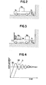
- Fig. 2 is a view illustrating a vibration system of the pulse motor excepting the damper 20.
- M1 denotes the mass of the movable member 1
- M2 is the mass of a load attached to the movable member 1
- K1 is a spring costant corresponding to the retaining force of the pulse motor
- C1 is a constant indicative of resistance such as friction to reduce the vibration of the movable member 1.
- a method is considered of providing on the movable member 1, a second vibration system having a resonance frequency being approximately f1 for thereby cancelling out the vibraiton of the movable member 1.
- Fig. 3 is a view illustrating the vibration system of the pulse motor wherein the damper 20 being the second vibration system is mounted on the movable member 1.
- M3 is the mass of the damper
- k2 is the spring constant of the damper
- C2 is a constant indicative of viscosity of the damper 20.
- the damper 20 is not subjected to the any force until the movable membner 1 is moved. For this, the dampere 20 is moved slightly delayed with respect to the movement of the movable member 1. Then the damper 20 does not stop owing to the inertia of itself although the movable member 1 reaches a prescribed position and stops, and tries to go forward in the moving direction of the movable member. Therefore, the damper 20 vibrates at its resonance frequency approximately equal to that of the pulse motor but in the opposite phase where the direction of the vibration there is reversed. This vibration is sustained for a period of time specified by the constant C2 of the resistance.
- Fig. 4 shows the situation described above.
- the numeral 30 is a curve showing the displacement of the movable member 1 of the pulse motor excepting the damper 20
- the numeral 31 is a curve showing the displacement of the damper 20
- the numeral 32 is a straight line disignating on the graph, a prescribed position of the movable member 1 to be stopped.
- the movable member 1 excepting the damper 20 and the damper 20 vibrate around the prescribed position 32 at the frequency substantially equal to each other in the opposite direction.
- the movable member 1 is cancelled out in its vibration in the vicinity of the prescribed position 32 owing to the vibration of the damper 20.
- the damper 20 is mounted on the fixed member 2 since when the pulse motor is employed for driving print heads of a printer and a typerwriter, etc., the movable member 1 is fixed on each of the bodies thereof.
- the damper 20 may not only be mounted on the movable member 1 along the moving direction thereof, but be mounted thereon in a direction perpendicular to the above moving direction.
- the damper 20 may not only be mounted on the movable member 1 or the fixed member 2, but may be mounted for example on a load attached to te movable member 1 or the fixed member 2.
- the fixed member was described as the primary member while the movable member as the secondary member, they are employed relatively, i.e., the fixed member and the movable member may be either of the primary and the secondary members.
- Fig. 5 (a) is a cross sectional view illustrating the arrangement of the first embodiment of the seocnd invention.
- a substantially disk-shaped back plate 13 having a mounting part 513b is fitted to the shaft 502 of a pulse motor, and fixedly mounted by means of a screw 514.
- An annular permanent magnet 510 is fixedly mounted on the vertical flat plate part 513a of the back plate 513, which magnet has two poles magnetized as shown in Fig. 5 (b).
- a spacer 515 made of a slidable material such as Teflon is attached to the other surface of the permanent magnet 510, and an inertia member 516 having the same shape as that of the permanent magnet 510 is disposed in contact with the other surface of the spacer 515.
- This inertia member 516 consists of an annual permanent magnet having two poles magnetized as shown in Fig. 5 (c) and a back plate 517 having the same shape as that of the permanent magnet 512 and bonded to the permanent magnet 512.
- FIG. 6 shows a relatioship between angles of relative rotaiton of the respective magnets 10, 12 from a normal opposing position of the permanent magnets 10, 12 (a position where the pole S of the permanent magnet 510 is opposed to the pole N of the permanent magnet 12) and torque T exerted between the above respective magnets 10, 12.
- the torgue T is O when the angle of rotation is ⁇ , i.e., the permanent magnets 510, 512 are located at the normal opposing position, and the torque T becomes maximum when the above angle ⁇ is 90oC.
- the inertia member 516 is left behind from the rotation of the shaft 502 owing to the inertia force thereof to cause a displacement between the permanent magnets 510 and 512, whereby the toreque T is response to the angle of rotation is produced between the magnets 510, 512 as shown in Fig. 6.
- This torque serves as centripetal force to return the magnet 512 to the normal oppositing position.
- the operation of the magnet 512 is as follows:
- a rotor of the pulse motor excepting the inertia member 516 also has a natural frequency established with quite the same relation as the above equation, i.e., a natural frequency f2 determined by the torque constant of the same motor and the inertia of the rotor, and vibrates at the frequency f2. Therefore, provided the natural frequency f2 of the rotor is made eaul to that f1 of the inertia member 16, the vibration of the pulse motor can rapidly be damped.
- Fig. 7 shows this situation.
- the symbol l1 is a curve showing the rotor displacement of the pulse motor excepting the inertia member 16
- l2 is a curve showing the displacement of the inertia member 16
- l3 is a straight line showing the stoppage position of the rotor.
- the rotor of the pulse motor excepting the inertia member 516 and the inetia member 516 vibrate around the stoppage position 3 at the respective natural frequencies f2 and f1 substantially equal to each other but in the opposite phase.
- the vibration of the rotor of the same motor is cancelled out owing to the vibration of the inertia member 16 to cause the rapid stoppage of the rotor.
- each of the permanent magnet 510 on the driving side and the permanent magnet 512 on the inertia member side was adapted to be two magnetized poles, but they may be adapted to be multiple poles magnetized as shown in Figs. 8(a) and (b).
- the spring constant of the inertia member can be improved.
- outer oppossing circumferential parts of the respecitve magnets 510, 512 may be circular arc-shaped as showin in Fig. 9.
- the movement of the inertia member can further be smoothed.
- the spacer 15 is not necessarily needed, but lack of spacer of this type causes too strong magnetic attraction between the permanent magnets 10 and 12.
- the spacer is preferably provided.
- Figs. 10 and 11 are respectively a perspecitve view illustrating the arrangement of a vibration damping apparatus 630 accoridng to the second embodiment of the second invention and a side elevational view illustrating the same apparatus 630.
- the numeral 632 designates a mounting plate, to the lowe surface of which a permanent magnet 633 is bonded.
- the numeral 634 is a damping member having the same shape as that of the permanent magnet 633, which consists of the permanent magnet 635 and a back plate 636 bonded to the magnet 635.
- the damping member 634 and a slider 638 excepting the damping member 634 being preeviously set to be equal in their natural frequencies
- the damping member 634 is joinned with the permanent magnet 633 with the aid of the magnetic attraction. Accordingly, provided acceleration of the slider 638 is low, the permanent magnets 633 ands 634 are integrally coupled. In such a manner, the mounting plate 632, permanent magnet 633, ands damping member 634 described above construct the damping apparatus 630.
- a damper constructed at least in part with a viscoelastic member is mounted at least one of the fixed member and the movable member, the natural frequency of which damper is in turn substantially equal to the natural frequency of the damper.
- a vibratrion damping apparatus was adapted to have the first permanent magnet fixedly mounted on the movable member of a linear pulse motor and the second permanent magnet provided in opposition to the first permanent magnet.
- the natual frequency of the second permanent maganet was made equal to that of the movable member of the pulse motor excepting the second permanent magnet.
Landscapes
- Engineering & Computer Science (AREA)
- Power Engineering (AREA)
- Linear Motors (AREA)
- Connection Of Motors, Electrical Generators, Mechanical Devices, And The Like (AREA)
- Vibration Prevention Devices (AREA)
Applications Claiming Priority (4)
| Application Number | Priority Date | Filing Date | Title |
|---|---|---|---|
| JP61002833A JPS62163557A (ja) | 1986-01-09 | 1986-01-09 | リニアパルスモ−タ−の振動抑制機構 |
| JP2833/86 | 1986-01-09 | ||
| JP37306/86 | 1986-03-14 | ||
| JP3730686U JPH0235083Y2 (de) | 1986-03-14 | 1986-03-14 |
Publications (2)
| Publication Number | Publication Date |
|---|---|
| EP0229013A2 true EP0229013A2 (de) | 1987-07-15 |
| EP0229013A3 EP0229013A3 (de) | 1989-05-10 |
Family
ID=26336301
Family Applications (1)
| Application Number | Title | Priority Date | Filing Date |
|---|---|---|---|
| EP87100059A Withdrawn EP0229013A3 (de) | 1986-01-09 | 1987-01-05 | Vorrichtung zur Schwingungsdämpfung für einen Schrittmotor |
Country Status (3)
| Country | Link |
|---|---|
| US (1) | US4938325A (de) |
| EP (1) | EP0229013A3 (de) |
| KR (1) | KR920010955B1 (de) |
Cited By (2)
| Publication number | Priority date | Publication date | Assignee | Title |
|---|---|---|---|---|
| US10659885B2 (en) | 2014-09-24 | 2020-05-19 | Taction Technology, Inc. | Systems and methods for generating damped electromagnetically actuated planar motion for audio-frequency vibrations |
| US11263879B2 (en) | 2015-09-16 | 2022-03-01 | Taction Technology, Inc. | Tactile transducer with digital signal processing for improved fidelity |
Families Citing this family (6)
| Publication number | Priority date | Publication date | Assignee | Title |
|---|---|---|---|---|
| JPH02240440A (ja) | 1989-03-14 | 1990-09-25 | Shiigeru:Kk | 慣性ダンパ |
| EP0748027B1 (de) * | 1995-06-07 | 2006-09-06 | General Electric Company | Dynamoelektrische Maschine und deren Rotorkonstruktion |
| US6191510B1 (en) | 1997-12-19 | 2001-02-20 | 3M Innovative Properties Company | Internally damped stator, rotor, and transformer and a method of making |
| US5924312A (en) * | 1997-12-23 | 1999-07-20 | Maytag Corporation | Multiple direction vibration absorber |
| WO2001065555A1 (en) * | 2000-02-29 | 2001-09-07 | Koninklijke Philips Electronics N.V. | Recording and/or reproducing apparatus having means for damping vibrations of a component part which cooperates with a record carrier in the form of a tape |
| DE102006042301B4 (de) * | 2006-09-08 | 2018-02-22 | Ellergon Antriebstechnik Gmbh | Membranausgleichskupplung und Lochlaibungsverbindung |
Family Cites Families (11)
| Publication number | Priority date | Publication date | Assignee | Title |
|---|---|---|---|---|
| DE2123654B2 (de) * | 1971-05-13 | 1973-11-22 | Maschinenfabrik Augsburg-Nuernberg Ag, 8000 Muenchen | Dampfungsvorrichtung fur einen schnell umlaufenden Rotationskörper |
| US3790831A (en) * | 1972-06-09 | 1974-02-05 | Computer Devices | Apparatus for damping oscillations in a stepping motor |
| AU504982B2 (en) * | 1975-06-18 | 1979-11-01 | Vdo Adolf Schindling Aktiengesellschaft | Damping device for a stepping motor |
| DE2603689C3 (de) * | 1976-01-31 | 1979-02-22 | Ibm Deutschland Gmbh, 7000 Stuttgart | Anordnung zum Schwingungsausgleich |
| US4200003A (en) * | 1976-03-29 | 1980-04-29 | Facet Enterprises, Inc. | Magnetic viscous damper |
| DD132515B1 (de) * | 1977-07-04 | 1979-11-28 | Horst Buge | Antrieb fuer maschinen mit periodisch veraenderlicher belastung,insbesondere fuer tagebaugrossgeraete |
| JPS57137737A (en) * | 1981-02-17 | 1982-08-25 | Toshiba Corp | Vibration-damping device for column |
| JPS57137738A (en) * | 1981-02-18 | 1982-08-25 | Toshiba Corp | Vibration-damping device for column |
| US4406642A (en) * | 1981-04-13 | 1983-09-27 | Dresser Industries, Inc. | Shaft dampening apparatus |
| US4598328A (en) * | 1983-05-09 | 1986-07-01 | Xerox Corporation | Mechanical damper for disk drives having band drive actuators |
| GB2192041B (en) * | 1986-06-24 | 1990-10-10 | Fokker Bv | Vibration absorber with controllable resonance frequency |
-
1987
- 1987-01-05 EP EP87100059A patent/EP0229013A3/de not_active Withdrawn
- 1987-01-08 KR KR1019870000069A patent/KR920010955B1/ko not_active Expired
-
1988
- 1988-09-20 US US07/247,067 patent/US4938325A/en not_active Expired - Fee Related
Cited By (4)
| Publication number | Priority date | Publication date | Assignee | Title |
|---|---|---|---|---|
| US10659885B2 (en) | 2014-09-24 | 2020-05-19 | Taction Technology, Inc. | Systems and methods for generating damped electromagnetically actuated planar motion for audio-frequency vibrations |
| US10812913B2 (en) | 2014-09-24 | 2020-10-20 | Taction Technology, Inc. | Systems and methods for generating damped electromagnetically actuated planar motion for audio-frequency vibrations |
| US10820117B2 (en) | 2014-09-24 | 2020-10-27 | Taction Technology, Inc. | Systems and methods for generating damped electromagnetically actuated planar motion for audio-frequency vibrations |
| US11263879B2 (en) | 2015-09-16 | 2022-03-01 | Taction Technology, Inc. | Tactile transducer with digital signal processing for improved fidelity |
Also Published As
| Publication number | Publication date |
|---|---|
| US4938325A (en) | 1990-07-03 |
| KR870007595A (ko) | 1987-08-20 |
| KR920010955B1 (ko) | 1992-12-24 |
| EP0229013A3 (de) | 1989-05-10 |
Similar Documents
| Publication | Publication Date | Title |
|---|---|---|
| JPS61154487A (ja) | リニア振動波モ−タ | |
| WO1996037347A1 (en) | Vibratory linear actuator and method of driving the same | |
| JP2007506539A (ja) | 振動変位を発生させるための電気モータを有する小型電気器具 | |
| JPS625069B2 (de) | ||
| EP0229013A2 (de) | Vorrichtung zur Schwingungsdämpfung für einen Schrittmotor | |
| US3790831A (en) | Apparatus for damping oscillations in a stepping motor | |
| JPS60207440A (ja) | 振動モータ | |
| JP2752248B2 (ja) | リニアモータ装置 | |
| EP0967022B1 (de) | Vorrichtung zur Erzeugung von Vibrationen | |
| EP0442443B1 (de) | Betätigungsvorrichtung für optische Einheit für ein Gerät zur Aufzeichnung/Wiedergabe | |
| GB2086003A (en) | Vibratory Feeder | |
| US3644764A (en) | Harmonic drive for digital step motor | |
| EP0353074B1 (de) | Linearantrieb | |
| JPH07265560A (ja) | 往復式電気かみそり | |
| JP3029697B2 (ja) | 並進形磁気ダンパ装置 | |
| JPH0235083Y2 (de) | ||
| US5191258A (en) | Electric current generator including torque reducing countermagnetic field | |
| JPS62163557A (ja) | リニアパルスモ−タ−の振動抑制機構 | |
| JP2651732B2 (ja) | 直線駆動装置 | |
| US4516062A (en) | Actuator | |
| JP3796634B2 (ja) | 平面リニアパルスモータの制振制御方法および制振制御装置 | |
| JPS59156149A (ja) | リニヤモ−タ | |
| JPH0429554A (ja) | ステッピングモータ | |
| JPH0670530A (ja) | 回転型アクチュエータ | |
| JP3427565B2 (ja) | 往復式電気かみそり |
Legal Events
| Date | Code | Title | Description |
|---|---|---|---|
| PUAI | Public reference made under article 153(3) epc to a published international application that has entered the european phase |
Free format text: ORIGINAL CODE: 0009012 |
|
| AK | Designated contracting states |
Kind code of ref document: A2 Designated state(s): DE FR GB |
|
| 17P | Request for examination filed |
Effective date: 19880121 |
|
| PUAL | Search report despatched |
Free format text: ORIGINAL CODE: 0009013 |
|
| AK | Designated contracting states |
Kind code of ref document: A3 Designated state(s): DE FR GB |
|
| 17Q | First examination report despatched |
Effective date: 19911015 |
|
| STAA | Information on the status of an ep patent application or granted ep patent |
Free format text: STATUS: THE APPLICATION IS DEEMED TO BE WITHDRAWN |
|
| 18D | Application deemed to be withdrawn |
Effective date: 19941109 |
|
| RIN1 | Information on inventor provided before grant (corrected) |
Inventor name: NAKAGAWA, HIROSHI |