EP0229059B1 - Incinerateur - Google Patents
Incinerateur Download PDFInfo
- Publication number
- EP0229059B1 EP0229059B1 EP85903894A EP85903894A EP0229059B1 EP 0229059 B1 EP0229059 B1 EP 0229059B1 EP 85903894 A EP85903894 A EP 85903894A EP 85903894 A EP85903894 A EP 85903894A EP 0229059 B1 EP0229059 B1 EP 0229059B1
- Authority
- EP
- European Patent Office
- Prior art keywords
- passageway
- grate
- feed
- screw
- fuel
- Prior art date
- Legal status (The legal status is an assumption and is not a legal conclusion. Google has not performed a legal analysis and makes no representation as to the accuracy of the status listed.)
- Expired
Links
- 239000000446 fuel Substances 0.000 claims abstract description 14
- 238000004140 cleaning Methods 0.000 claims description 3
- 239000002826 coolant Substances 0.000 claims 2
- 238000001816 cooling Methods 0.000 description 7
- 239000002893 slag Substances 0.000 description 6
- XLYOFNOQVPJJNP-UHFFFAOYSA-N water Substances O XLYOFNOQVPJJNP-UHFFFAOYSA-N 0.000 description 5
- 238000010304 firing Methods 0.000 description 2
- 239000000463 material Substances 0.000 description 2
- 239000011449 brick Substances 0.000 description 1
- 230000001419 dependent effect Effects 0.000 description 1
- 230000000694 effects Effects 0.000 description 1
- 238000004519 manufacturing process Methods 0.000 description 1
- 239000002184 metal Substances 0.000 description 1
- 230000001681 protective effect Effects 0.000 description 1
- 238000007789 sealing Methods 0.000 description 1
- 239000004449 solid propellant Substances 0.000 description 1
Images

Classifications
-
- F—MECHANICAL ENGINEERING; LIGHTING; HEATING; WEAPONS; BLASTING
- F23—COMBUSTION APPARATUS; COMBUSTION PROCESSES
- F23K—FEEDING FUEL TO COMBUSTION APPARATUS
- F23K3/00—Feeding or distributing of lump or pulverulent fuel to combustion apparatus
- F23K3/10—Under-feed arrangements
- F23K3/14—Under-feed arrangements feeding by screw
-
- F—MECHANICAL ENGINEERING; LIGHTING; HEATING; WEAPONS; BLASTING
- F23—COMBUSTION APPARATUS; COMBUSTION PROCESSES
- F23G—CREMATION FURNACES; CONSUMING WASTE PRODUCTS BY COMBUSTION
- F23G5/00—Incineration of waste; Incinerator constructions; Details, accessories or control therefor
- F23G5/32—Incineration of waste; Incinerator constructions; Details, accessories or control therefor the waste being subjected to a whirling movement, e.g. cyclonic incinerators
-
- F—MECHANICAL ENGINEERING; LIGHTING; HEATING; WEAPONS; BLASTING
- F23—COMBUSTION APPARATUS; COMBUSTION PROCESSES
- F23G—CREMATION FURNACES; CONSUMING WASTE PRODUCTS BY COMBUSTION
- F23G2205/00—Waste feed arrangements
- F23G2205/12—Waste feed arrangements using conveyors
- F23G2205/121—Screw conveyor
Definitions
- This invention relates to a device at incinerators and, more precisely, to a feed-in device for fuel into such incinerator comprising a fire-place with plane grate.
- the device is particularly suitable for use at incinerators of cyclone type where fuel is fed-in through an opening in the grate.
- the fuel is supplied from below through an angularly bent supply passageway and centrally in through the grate.
- Solid fuel for example bark, shivers and chips, is hereby compressed which causes the fuel to get stuck.
- the conventional devices moreover, yield an unfavourable fuel distribution on the grate and require much energy. It is also a problem with prior known devices to clean the feed-in pipe.
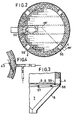
- Fig. 1 is a cross-section of an incinerator with feed-in device
- Fig. 2 is a view from above of the grate arrangement
- Fig. 3 shows a detail of the slag outlet
- Fig. 4 shows a device for secondary air supply.
- FIG. 1 an incinerator 1 with a hearth jacket 2 and embedded protective bricks 3 is shown.
- the incinerator is provided with a plane grate 5, which is supported on beams 6.
- the ash space 7 is enclosed by a sheet metal casing 8 and directed downward to a trough 9 located beneath the incinerator.
- the trough is filled with water, and the downward extension from the ash space terminates below the water surface in such a way as to act as a water seal.
- a conveyor screw or scraper (not shown) is mounted for ash removal.
- the fuel which consists of bark or chips, is supplied by means of a screw 33 and through a slide 23 to the feed-in device positioned according to the invention.
- nozzles 42, 43 from a distribution chamber are located, through which secondary air is supplied for combusting the material gasified on the grates of the fire-place.
- the nozzles are directed tangentially for bringing about a cyclone effect.
- a movable portion 34 is provided, which is detachable from the rigidly mounted portion and mounted on a bottom plate 19 at the foundation 20.
- the fuel is charged into the incinerator by means of a screw 11, the thread pitch of which increases successively toward the inlet in the incinerator.
- the screw is supported in two positions 25 outside the feed-in pipe and, together with the movable portion 34 of the pipe, can be pulled out for cleaning and reconditioning.
- On said plate 19 also a hydraulic motor 26 for operating the screw is mounted.
- the movable portion 34 is provided with a cleaning door 27.
- the grate plates as shown in Fig. 2, to the greatest extent shall be square and of equal dimensions, in order to be easily exchangeable wherever in the grate surface they are located, and in order to reduce the manufacturing costs and to have to store in the spare parts stock only a small number of types.
- the area closest to the inlet of the feed-in pipe in the grate surface is covered by grate plates without holes.
- the opening between grate plates and the feed-in pipe is covered by a loosely mounted ring, which is cooled by air from the feed-in pipe, which is provided with a cooling jacket.
- guide bars are inserted to counteract the cooling air and prevent it from "going the shortest way" upward beneath the grates and, respectively, between the feed-in pipe and the loosely mounted sealing ring.
- Cooling of the feed-in pipe counteracts deformation by heat, which can occur in the case of fire beneath the grates (when fine-grained material has fallen down beneath the grates and been ignited), as well as in the case of down-firing for slagging when fuel can remain in the uppermost part of the feed-in pipe and glow.
- the grate plates closest to the feed-in pipe have no holes.
- Openings 56 for slag removal are located at the lower edge of the lead-in 4 in the incinerator wall for slag doors. These openings are covered by doors, which are lifted out at slagging or can be provided with damper blades of various design.
- the ash space is formed so that the slag from the aforesaid openings is directed downward to a water-filled trough 9, which can be provided with a scraper conveyor for removing the slag to the container or the like.
- the connection between the "ash bin" and trough must be formed as a water seal, because the primary air beneath the grates produces over-pressure in the ash space.
- the fuel feed-in pipe is assembled of two parts.
- the bolt connections 17 and 18 are loosened, and the bottom plate 19 is loosened from the foundation 20.
- the screw is swung to the side of the slide 23 and can then be lifted away together with what else is attached to the bottom plate 19.
Landscapes
- Engineering & Computer Science (AREA)
- Mechanical Engineering (AREA)
- General Engineering & Computer Science (AREA)
- Chemical & Material Sciences (AREA)
- Combustion & Propulsion (AREA)
- Solid-Fuel Combustion (AREA)
- Incineration Of Waste (AREA)
Abstract
Claims (8)
Priority Applications (1)
| Application Number | Priority Date | Filing Date | Title |
|---|---|---|---|
| AT85903894T ATE51439T1 (de) | 1984-09-17 | 1985-07-31 | Verbrennungsvorrichtung. |
Applications Claiming Priority (2)
| Application Number | Priority Date | Filing Date | Title |
|---|---|---|---|
| SE8404656A SE449253B (sv) | 1984-09-17 | 1984-09-17 | Inmatningsanordning for brensle |
| SE8404656 | 1984-09-17 |
Publications (2)
| Publication Number | Publication Date |
|---|---|
| EP0229059A1 EP0229059A1 (fr) | 1987-07-22 |
| EP0229059B1 true EP0229059B1 (fr) | 1990-03-28 |
Family
ID=20357040
Family Applications (1)
| Application Number | Title | Priority Date | Filing Date |
|---|---|---|---|
| EP85903894A Expired EP0229059B1 (fr) | 1984-09-17 | 1985-07-31 | Incinerateur |
Country Status (9)
| Country | Link |
|---|---|
| US (1) | US4667606A (fr) |
| EP (1) | EP0229059B1 (fr) |
| JP (1) | JPS61501585A (fr) |
| CA (1) | CA1263823A (fr) |
| DE (1) | DE3576847D1 (fr) |
| DK (1) | DK167079B1 (fr) |
| FI (1) | FI871154A7 (fr) |
| SE (1) | SE449253B (fr) |
| WO (1) | WO1986001877A1 (fr) |
Families Citing this family (4)
| Publication number | Priority date | Publication date | Assignee | Title |
|---|---|---|---|---|
| US5680821A (en) * | 1994-02-04 | 1997-10-28 | Advanced Envirotech Systems, Inc. | Solid waste handling and conveying apparatus |
| US5730072A (en) * | 1995-10-17 | 1998-03-24 | Advanced Envirotech Systems, Inc. | Method and system for continuous rapid incineration of solid waste in an oxygen-rich environment |
| IT201700004910A1 (it) * | 2017-01-18 | 2018-07-18 | Dielle S R L | Sistema di caricamento per caricare combustibile in un braciere di un sistema a biomassa, in particolare pellet in un braciere di una stufa a pellet. |
| US11125432B2 (en) * | 2018-05-31 | 2021-09-21 | Edward Norbert Endebrock | Solid particle fuel burner |
Family Cites Families (11)
| Publication number | Priority date | Publication date | Assignee | Title |
|---|---|---|---|---|
| DE160759C (fr) * | ||||
| DE125590C (fr) * | 1900-03-23 | |||
| US691328A (en) * | 1901-02-21 | 1902-01-14 | Isaac D Smead | Combined crematory and heating system. |
| US737306A (en) * | 1902-09-27 | 1903-08-25 | Harry L Wilson | Automatic stoker. |
| US1711466A (en) * | 1926-04-28 | 1929-04-30 | Standard Stoker Co Inc | Locomotive stoker |
| US2228947A (en) * | 1937-08-24 | 1941-01-14 | James A Casey | Automatic stoker |
| US2365679A (en) * | 1941-11-25 | 1944-12-26 | James A Casey | Underfed stoker |
| JPS4938482A (fr) * | 1972-08-15 | 1974-04-10 | ||
| SE400627B (sv) * | 1976-07-19 | 1978-04-03 | Nyholm Erik August | Sekerhetsanordning vid flisugn |
| US4384534A (en) * | 1980-10-27 | 1983-05-24 | Enterprises International, Inc. | Ash removal system and heating mechanism for wood waste burners |
| JPS5852424B2 (ja) * | 1982-05-27 | 1983-11-22 | 松下電工株式会社 | コイル筒の製法 |
-
1984
- 1984-09-17 SE SE8404656A patent/SE449253B/sv not_active IP Right Cessation
-
1985
- 1985-07-31 US US06/862,218 patent/US4667606A/en not_active Expired - Fee Related
- 1985-07-31 EP EP85903894A patent/EP0229059B1/fr not_active Expired
- 1985-07-31 DE DE8585903894T patent/DE3576847D1/de not_active Expired - Fee Related
- 1985-07-31 WO PCT/SE1985/000297 patent/WO1986001877A1/fr not_active Ceased
- 1985-07-31 JP JP60503467A patent/JPS61501585A/ja active Pending
- 1985-07-31 FI FI871154A patent/FI871154A7/fi not_active Application Discontinuation
- 1985-09-16 CA CA000490776A patent/CA1263823A/fr not_active Expired
-
1986
- 1986-04-23 DK DK185886A patent/DK167079B1/da active
Also Published As
| Publication number | Publication date |
|---|---|
| FI871154L (fi) | 1987-03-17 |
| SE449253B (sv) | 1987-04-13 |
| FI871154A0 (fi) | 1987-03-17 |
| JPS61501585A (ja) | 1986-07-31 |
| DE3576847D1 (de) | 1990-05-03 |
| DK185886D0 (da) | 1986-04-23 |
| CA1263823A (fr) | 1989-12-12 |
| DK185886A (da) | 1986-04-23 |
| FI871154A7 (fi) | 1987-03-17 |
| SE8404656D0 (sv) | 1984-09-17 |
| SE8404656L (sv) | 1986-03-18 |
| US4667606A (en) | 1987-05-26 |
| DK167079B1 (da) | 1993-08-23 |
| EP0229059A1 (fr) | 1987-07-22 |
| WO1986001877A1 (fr) | 1986-03-27 |
Similar Documents
| Publication | Publication Date | Title |
|---|---|---|
| US3592151A (en) | Method and apparatus for refuse incineration | |
| EP1384032B1 (fr) | Dispositif de combustion | |
| US4836115A (en) | Vertical furnace | |
| EP2400217B1 (fr) | Brûleur fermé pour brûler du combustible granulaire | |
| US4672899A (en) | Preburning plant for burning solid fuel materials having a high ash contents | |
| EP0128162A1 (fr) | Chargeur automatique de combustible solide | |
| EP0229059B1 (fr) | Incinerateur | |
| US5273209A (en) | Heat exchange and fuel feed apparatus for vertical furnace | |
| RU2125584C1 (ru) | Топочная камера для твердого материала | |
| US8261677B2 (en) | Gasification boiler for solid fuels, in particular for bales of straw, with optimised exhaust gas values | |
| JPS625242B2 (fr) | ||
| US6024028A (en) | Protection of the air ports of a recovery boiler | |
| WO1981002057A1 (fr) | Chambres de combustion a lit gicle et fluidise | |
| WO2009061272A1 (fr) | Brûleur pour la combustion de combustible solide granulaire | |
| EP1387984A1 (fr) | Procede permettant de bruler des combustibles solides dans un bruleur et dispositif permettant de mettre en oeuvre ce procede | |
| JP3140180B2 (ja) | ボイラ | |
| CN213334344U (zh) | 一种一体式生物质燃烧机 | |
| US4726765A (en) | Combustor drum hole shields | |
| CN2316561Y (zh) | 一种通用垃圾连续焚烧炉 | |
| RU2335697C2 (ru) | Сопло решетки реактора с псевдоожиженным слоем | |
| CN224135868U (zh) | 一种循环流化床焚烧炉布风装置 | |
| JPS59158909A (ja) | 産業廃棄物溶融炉 | |
| CN213746699U (zh) | 一种节能环保型生物质颗粒炉 | |
| EP2944680B1 (fr) | Réacteur de gazéification | |
| CN219934022U (zh) | 一种化工用节能型锅炉 |
Legal Events
| Date | Code | Title | Description |
|---|---|---|---|
| PUAI | Public reference made under article 153(3) epc to a published international application that has entered the european phase |
Free format text: ORIGINAL CODE: 0009012 |
|
| 17P | Request for examination filed |
Effective date: 19870226 |
|
| AK | Designated contracting states |
Kind code of ref document: A1 Designated state(s): AT CH DE FR GB LI SE |
|
| 17Q | First examination report despatched |
Effective date: 19880613 |
|
| GRAA | (expected) grant |
Free format text: ORIGINAL CODE: 0009210 |
|
| AK | Designated contracting states |
Kind code of ref document: B1 Designated state(s): AT CH DE FR GB LI SE |
|
| REF | Corresponds to: |
Ref document number: 51439 Country of ref document: AT Date of ref document: 19900415 Kind code of ref document: T |
|
| REF | Corresponds to: |
Ref document number: 3576847 Country of ref document: DE Date of ref document: 19900503 |
|
| ET | Fr: translation filed | ||
| PLBE | No opposition filed within time limit |
Free format text: ORIGINAL CODE: 0009261 |
|
| STAA | Information on the status of an ep patent application or granted ep patent |
Free format text: STATUS: NO OPPOSITION FILED WITHIN TIME LIMIT |
|
| 26N | No opposition filed | ||
| PGFP | Annual fee paid to national office [announced via postgrant information from national office to epo] |
Ref country code: GB Payment date: 19930723 Year of fee payment: 9 |
|
| PGFP | Annual fee paid to national office [announced via postgrant information from national office to epo] |
Ref country code: AT Payment date: 19930729 Year of fee payment: 9 |
|
| PGFP | Annual fee paid to national office [announced via postgrant information from national office to epo] |
Ref country code: CH Payment date: 19930805 Year of fee payment: 9 |
|
| PG25 | Lapsed in a contracting state [announced via postgrant information from national office to epo] |
Ref country code: LI Effective date: 19940731 Ref country code: GB Effective date: 19940731 Ref country code: CH Effective date: 19940731 Ref country code: AT Effective date: 19940731 |
|
| PGFP | Annual fee paid to national office [announced via postgrant information from national office to epo] |
Ref country code: SE Payment date: 19940825 Year of fee payment: 10 |
|
| PGFP | Annual fee paid to national office [announced via postgrant information from national office to epo] |
Ref country code: FR Payment date: 19950124 Year of fee payment: 10 |
|
| EAL | Se: european patent in force in sweden |
Ref document number: 85903894.5 |
|
| PGFP | Annual fee paid to national office [announced via postgrant information from national office to epo] |
Ref country code: DE Payment date: 19950202 Year of fee payment: 10 |
|
| GBPC | Gb: european patent ceased through non-payment of renewal fee |
Effective date: 19940731 |
|
| REG | Reference to a national code |
Ref country code: CH Ref legal event code: PL |
|
| PG25 | Lapsed in a contracting state [announced via postgrant information from national office to epo] |
Ref country code: SE Effective date: 19950801 |
|
| PG25 | Lapsed in a contracting state [announced via postgrant information from national office to epo] |
Ref country code: DE Effective date: 19960402 |
|
| PG25 | Lapsed in a contracting state [announced via postgrant information from national office to epo] |
Ref country code: FR Effective date: 19960430 |
|
| REG | Reference to a national code |
Ref country code: FR Ref legal event code: ST |
|
| EUG | Se: european patent has lapsed |
Ref document number: 85903894.5 |
|
| REG | Reference to a national code |
Ref country code: FR Ref legal event code: ST |
|
| REG | Reference to a national code |
Ref country code: FR Ref legal event code: ST |