EP0229093B1 - Verfahren zum dampfkracken von kohlenwasserstoffen - Google Patents
Verfahren zum dampfkracken von kohlenwasserstoffen Download PDFInfo
- Publication number
- EP0229093B1 EP0229093B1 EP86903438A EP86903438A EP0229093B1 EP 0229093 B1 EP0229093 B1 EP 0229093B1 EP 86903438 A EP86903438 A EP 86903438A EP 86903438 A EP86903438 A EP 86903438A EP 0229093 B1 EP0229093 B1 EP 0229093B1
- Authority
- EP
- European Patent Office
- Prior art keywords
- zone
- channels
- section
- pyrolysis
- mixture
- Prior art date
- Legal status (The legal status is an assumption and is not a legal conclusion. Google has not performed a legal analysis and makes no representation as to the accuracy of the status listed.)
- Expired
Links
Images
Classifications
-
- C—CHEMISTRY; METALLURGY
- C10—PETROLEUM, GAS OR COKE INDUSTRIES; TECHNICAL GASES CONTAINING CARBON MONOXIDE; FUELS; LUBRICANTS; PEAT
- C10G—CRACKING HYDROCARBON OILS; PRODUCTION OF LIQUID HYDROCARBON MIXTURES, e.g. BY DESTRUCTIVE HYDROGENATION, OLIGOMERISATION, POLYMERISATION; RECOVERY OF HYDROCARBON OILS FROM OIL-SHALE, OIL-SAND, OR GASES; REFINING MIXTURES MAINLY CONSISTING OF HYDROCARBONS; REFORMING OF NAPHTHA; MINERAL WAXES
- C10G9/00—Thermal non-catalytic cracking, in the absence of hydrogen, of hydrocarbon oils
-
- B—PERFORMING OPERATIONS; TRANSPORTING
- B01—PHYSICAL OR CHEMICAL PROCESSES OR APPARATUS IN GENERAL
- B01J—CHEMICAL OR PHYSICAL PROCESSES, e.g. CATALYSIS OR COLLOID CHEMISTRY; THEIR RELEVANT APPARATUS
- B01J19/00—Chemical, physical or physico-chemical processes in general; Their relevant apparatus
- B01J19/24—Stationary reactors without moving elements inside
- B01J19/2415—Tubular reactors
- B01J19/2425—Tubular reactors in parallel
-
- B—PERFORMING OPERATIONS; TRANSPORTING
- B01—PHYSICAL OR CHEMICAL PROCESSES OR APPARATUS IN GENERAL
- B01J—CHEMICAL OR PHYSICAL PROCESSES, e.g. CATALYSIS OR COLLOID CHEMISTRY; THEIR RELEVANT APPARATUS
- B01J19/00—Chemical, physical or physico-chemical processes in general; Their relevant apparatus
- B01J19/24—Stationary reactors without moving elements inside
- B01J19/248—Reactors comprising multiple separated flow channels
- B01J19/2485—Monolithic reactors
-
- C—CHEMISTRY; METALLURGY
- C10—PETROLEUM, GAS OR COKE INDUSTRIES; TECHNICAL GASES CONTAINING CARBON MONOXIDE; FUELS; LUBRICANTS; PEAT
- C10G—CRACKING HYDROCARBON OILS; PRODUCTION OF LIQUID HYDROCARBON MIXTURES, e.g. BY DESTRUCTIVE HYDROGENATION, OLIGOMERISATION, POLYMERISATION; RECOVERY OF HYDROCARBON OILS FROM OIL-SHALE, OIL-SAND, OR GASES; REFINING MIXTURES MAINLY CONSISTING OF HYDROCARBONS; REFORMING OF NAPHTHA; MINERAL WAXES
- C10G9/00—Thermal non-catalytic cracking, in the absence of hydrogen, of hydrocarbon oils
- C10G9/14—Thermal non-catalytic cracking, in the absence of hydrogen, of hydrocarbon oils in pipes or coils with or without auxiliary means, e.g. digesters, soaking drums, expansion means
- C10G9/18—Apparatus
- C10G9/20—Tube furnaces
-
- F—MECHANICAL ENGINEERING; LIGHTING; HEATING; WEAPONS; BLASTING
- F28—HEAT EXCHANGE IN GENERAL
- F28F—DETAILS OF HEAT-EXCHANGE AND HEAT-TRANSFER APPARATUS, OF GENERAL APPLICATION
- F28F7/00—Elements not covered by group F28F1/00, F28F3/00 or F28F5/00
- F28F7/02—Blocks traversed by passages for heat-exchange media
-
- B—PERFORMING OPERATIONS; TRANSPORTING
- B01—PHYSICAL OR CHEMICAL PROCESSES OR APPARATUS IN GENERAL
- B01J—CHEMICAL OR PHYSICAL PROCESSES, e.g. CATALYSIS OR COLLOID CHEMISTRY; THEIR RELEVANT APPARATUS
- B01J2219/00—Chemical, physical or physico-chemical processes in general; Their relevant apparatus
- B01J2219/00049—Controlling or regulating processes
- B01J2219/00051—Controlling the temperature
- B01J2219/00074—Controlling the temperature by indirect heating or cooling employing heat exchange fluids
- B01J2219/00076—Controlling the temperature by indirect heating or cooling employing heat exchange fluids with heat exchange elements inside the reactor
- B01J2219/00085—Plates; Jackets; Cylinders
-
- B—PERFORMING OPERATIONS; TRANSPORTING
- B01—PHYSICAL OR CHEMICAL PROCESSES OR APPARATUS IN GENERAL
- B01J—CHEMICAL OR PHYSICAL PROCESSES, e.g. CATALYSIS OR COLLOID CHEMISTRY; THEIR RELEVANT APPARATUS
- B01J2219/00—Chemical, physical or physico-chemical processes in general; Their relevant apparatus
- B01J2219/00049—Controlling or regulating processes
- B01J2219/00051—Controlling the temperature
- B01J2219/00159—Controlling the temperature controlling multiple zones along the direction of flow, e.g. pre-heating and after-cooling
Definitions
- the invention relates to an improved process for steam cracking of hydrocarbons intended to produce light olefins, and more particularly ethylene and propylene.
- coke is due to side reactions such as the formation of condensed polycyclic aromatic hydrocarbons, as well as to the polymerization of the olefins formed.
- This latter reaction stems from the tendency of olefins to polymerize when the temperature is around 500 to 600 ° C; also to reduce the importance of this secondary reaction, it is necessary to carry out a rapid cooling (often called “quenching") of the reaction effluents so as to bring them quickly from the temperature where the pyrolysis takes place to a temperature below 500 ° C, generally thanks to an indirect heat exchanger.
- the evolution of the technology has mainly focused on the pyrolysis (b) and quenching (c) phases, in an attempt to satisfy the requirements mentioned above and the diversity of the charges to be treated, which extend to current time from ethane to vacuum diesel.
- the increase in this last factor can be essentially obtained by increasing the skin temperature of the tubular reactors and / or by reducing the diameter of the tubes (which makes it possible to increase the s / v ratio, s being the exchange surface and v the reaction volume).
- the technique has also evolved towards the use of smaller diameter tubes, placed in parallel in order to maintain a satisfactory capacity, and to remain in a suitable pressure drop range.
- the residence time of the charges is, in this type of oven, of the order of 0.07 s; the pressure drop observed is of the order of 0.9 to 1.8 bar, and the calculation of the ratio of the exchange surface s to the reaction volume v leads to values of the order of 120 m ⁇ 1 .
- exchangers The purpose of these exchangers is to carry out the abrupt reduction of the effluent gases from the pyrolysis reactors as quickly as possible to temperatures at which side reactions of the olefin polymerization type do not occur.
- the temperature to which the effluent is brought to the outlet of the quench exchanger varies as a function of the steam-cracked charge.
- TX "TLX" type exchangers have endeavored to reduce the dead volume existing between the outlets of the tubular reactors and the inlets of the effluents into the quenching exchanger, which is generally formed of two or three concentric tubes in order to increase the exchange surfaces.
- US Pat. No. 4,457,364 describes an exchanger of the TLX type which comprises a connector for distributing the effluent gases in which a reactor tube corresponds to two tubes of the exchange reactor; however, this connector does not entirely eliminate the problems of dead volume between reactor and quench exchanger.
- TLX type heat exchanger systems have two major drawbacks; they have a non-negligible dead volume, which is detrimental to rapid quenching, and they are constructed of refractory steels, containing nickel, which is, as already mentioned, a catalyst for the polymerization of olefins.
- the object of the present invention is to provide a process which overcomes these various drawbacks and allows the steam cracking of a hydrocarbon - or a mixture of hydrocarbons - comprising at least two carbon atoms, leading to improved yields of ethylene. and propylene compared to existing processes.
- the method of the invention is characterized in that a mixture of said hydrocarbon and water vapor is circulated in a continuous zone consisting of a plurality of channels of ceramic material forming two groups, each channel of the first group being in heat exchange relation with at least one channel of the second group, the channels of the first group extending over the entire length of said continuous zone and being traversed by said mixture, the channels of the second group being divided into two successive sections not -communicating by an intermediate partitioning and being supplied by a heating fluid in their first section (supply side of the mixture) and by a cooling fluid in their second section (outlet side of the mixture), said first and second section constituting respectively a pyrolysis zone and a quenching zone, the supply and withdrawal of the fluid heating effected perpendicular to the axis of the channels of the first section, said supply being effected at an intermediate point of the first section at a distance from the start of said first section (supply side of the mixture) representing 5 to 50% of the total length of the first section, and said drawing off
- the channels are preferably rectilinear and parallel to each other, and to each channel of the pyrolysis zone corresponds a channel of the quenching zone.
- each channel of a group is surrounded by channels of the other group on all of its faces.
- the channels of each group are arranged in rows, the channels being of any section but advantageously polygonal and preferably square or rectangular, the arrangement being designed so that the rows of order channels. .n - 2, n, n + 2, n + 4, ... are traversed by the load to be treated and that the other rows of channels of order ... n - 1, n + 1, n + 3, ... are traversed by heat transfer fluids over a first part of their length and by refrigerants over a subsequent part of their length, n being any number.
- the rows of channels traversed by the load are continuous over the total length of the system.
- the other rows of channels are divided into two successive parts by a partitioning at an intermediate point of their length, so as to define two zones, the channels of the first zone (in the direction of flow of the load to be treated) being traversed by a heat transfer fluid, thus determining a pyrolysis zone or reaction zone, the channels of the second zone being traversed by a cooling fluid thus determining a cooling zone, or quench zone.
- the system thus obtained therefore constitutes a continuous assembly of pyrolysis reactor and quench exchanger.
- the arrival of the heat transfer fluid in the rows of channels intended to convey it takes place substantially perpendicular to the axis of these rows of channels, by means of one or more openings made in the outer wall of the channels concerned situated at the periphery, and the channels of the same row are placed in communication at the level of the arrival of the heat-transfer fluid by openings made in their side walls, so that all of the channels intended for this purpose is traversed by the heat transfer fluid.
- the arrival of the heat transfer fluid in the pyrolysis zone takes place at an intermediate point of this zone, located at a distance from the start of this zone (the start being determined by the place of introduction of the charge) representing 5 to 50% of the total length of this zone, and more preferably 20 to 40% of the total length of this zone; in this way, the maximum heat input can be transmitted to the channels through which the charge passes where the endothermic cracking and dehydrogenation reactions take place.
- the heat transfer fluid is withdrawn both at the top and at the bottom of the pyrolysis zone. It is advantageous that 5 to 40% (preferably 20 to 35%) of the heating fluid is withdrawn at the head and the complement to 100% is withdrawn at the tail.
- the total number of rows of channels is not critical to the process; it is obviously a function of the size of the pyrolysis reactor-quench exchanger assembly and of the dimensions of a unitary channel.
- the two rows of external channels are, in the context of the invention, preferably traversed by heat transfer fluids or refrigerants.
- the number of unit channels per row is also not decisive and is a function of the overall dimension of the assembly and of the dimension of a unit channel.
- a unitary channel has a cross section advantageously between 9 and 900 mm 2 and preferably between 25 and 100 mm 2 ; the length of a unitary channel can be variable depending on the loads to be treated, the process temperature, the desired contact time and the temperature at which quenching is carried out.
- the total length of a unitary channel - comprising pyrolysis zone and quenching zone - is generally between 2 and 15 m and, preferably, between 5 and 10 m.
- each unit channel can be subdivided into a plurality of smaller elementary channels.
- the continuous pyrolysis reactor - quench exchanger assembly either in the form of a monobloc, or else by contiguous juxtaposition of unitary elements, of identical shape, which are assembled together by any suitable means, such as using clamps.
- the charges to be treated have a residence time in the reaction zone of between 5 and 200 milliseconds, and more advantageously between 30 and 50 milliseconds; the temperature of the walls in the reaction zone can be brought to a maximum value of the order of 1500 ° C.
- any refractory ceramic resistant to temperatures above 1150 ° C. can be used in the context of the invention; silicon carbide, which has good thermal conductivity and which is easily used by extrusion, is the ceramic preferentially used.
- Other ceramics are for example mullite, alumina and cordierite.
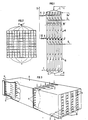
- FIG 1 there is shown a multi-channel assembly comprising a pyrolysis zone (A) and a quenching zone (B).
- the mixture constituted by the hydrocarbon feedstock to be treated and by steam is preheated, preferably by convection, in a conventional preheating zone not shown in the figure.
- the mixture On leaving this preheating zone, the mixture enters via the line (1) into the pyrolysis zone (A) where it is distributed by means of the distributor (C) in the plurality of reaction channels (D).
- the dotted line (M) is half the length of the pyrolysis zone (A); the heat transfer fluid inlet line (2) in zone (A) is located between (M) and (C) at a distance from the start of the pyrolysis zone (A) representing 5 to 50% of the total length of this zone; this heat transfer fluid is preferably constituted by combustion fumes coming for example from a burner not shown in the figure.
- the smoke outlet lines (3) and (4) include flow control systems (9 and 10), such as, for example, butterfly valves, making it possible to adjust the respective smoke flow rates between the outlets (3) and ( 4).
- flow control systems (9 and 10) such as, for example, butterfly valves, making it possible to adjust the respective smoke flow rates between the outlets (3) and ( 4).
- the sealing of the channels (F) by sealed sealing devices (J) makes it possible to delimit the pyrolysis (A) and quenching (B) zones.
- the coolant preferentially enters the quenching zone (B) through the line (6) located at the very beginning of the exchanger, and circulates in the channels (F ') parallel to the channels (D), co-current of the reaction effluents, and leaves the exchanger via line (7). It is possible, if necessary, to reverse the direction of circulation of the cooling fluid which, in this case, enters the exchange zone (B) by the line (7) and, after having cooled the reaction effluents against the current. , exits from (B) by line (6).
- reaction effluents thus cooled are collected in zone (E) and collected by line (8).
- these effluents can, if necessary, undergo a second quenching by direct addition of cold fluid, according to a known process.
- the subsequent effluent treatments are part of the prior art and are outside the scope of the present invention.
- FIG. 2 represents a section of a reactor element of rectangular section comprising square unit channels.
- reaction channels traversed by the charge to be treated are represented by the rows of channels (D) as described in FIG. 1.
- the channels traversed by the heat transfer fluid are represented by the hatched rows of channels (F) as described in FIG. 1.
- FIG. 3 represents an exploded perspective view of a module of the pyrolysis zone part (A) of the pyrolysis zone - quenching zone assembly.
- the charge distributor (C) described in Figure 1 is not shown.
- the designations used for the various elements are those in Figure 1.
- the path of the load to be treated is represented by the arrows (1); the charge enters the pyrolysis zone (A), is distributed in the plurality of unit channels (D), and passes longitudinally through the pyrolysis zone (A) in these multichannels (D) to exit the zone (A) by these same multichannel in (11); these multichannel D continue in the quenching zone not shown in the figure, which is immediately adjacent to the zone (A).
- the path followed by the heat transfer fluid is represented by the arrows located opposite the orifices (2); the heat transfer fluid enters (A) through the orifices (2) located in the first half of the zone (A); it is distributed in the plurality of unit channels (F), part of this fluid travels through these channels against the current of the charge flowing in the channels (D) and leaves (A) through the orifices (3); the other part of this fluid circulates in the channels (F) co-current with the load and leaves (A) through the orifices (4).
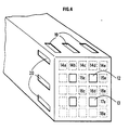
- FIG. 4 illustrates the case of channels such as 12 and 13, intended for the passage of the reactants and in contact on their 4 faces with channels for the heating fluid or the quenching fluid, such as 14a ... 14e, 15c, 15th, 16c, 16d, and 16th.
- the heating (or quenching) fluid is introduced laterally, preferably on two sides, for example through openings such as 19 and 20. Opposite these openings, free communication is established between the channels.
- the channels 14e, 15e, 16e, 17e and 18e communicate together while facing the opening 20, the channels 14a, 14b, 14c, 14d and 14e communicate together.
- heating or quenching fluid only on one face, for example the upper face, while maintaining internal communications between the channels indicated above. In this case there are no side openings such as 20.
- This charge is preheated to 550 ° C. after having been mixed with steam in a steam / charge weight ratio equal to 1.
- This charge is cracked in three installations, one known as “conventional” (A ) composed of cylindrical steel tubes in pins with an inside diameter of 60 mm and a length of 50 m; the second installation uses an “improved” process (B) using straight cylindrical steel tubes 30 mm inside diameter and 10 m long; the third installation (C) is in accordance with the invention and comprises a multichannel pyrolysis zone, made of silicon carbide, each channel having a square section of 10 mm in side and 3 m in length. These three installations operate so as to have an effluent temperature at the end of pyrolysis of 850 ° C.
- the heating fluid is introduced at 30% of the length of the pyrolysis zone; 25% of this fluid is withdrawn at the head and 75% at the tail.
- the products, pyrolysis effluents are cooled in the case of installations (A) and (B) using quenching exchangers made of metallic material, and the quenching exchanger (C) is in accordance with the invention, in silicon carbide, of the same structure and dimension as the multichannel pyrolysis zone and joined contiguously thereto by means of a flange.
- head and tail corresponds to a supply and a lateral racking, at points close to the ends of each structure, but not to the ends themselves where only the feeding and racking of reactive.
- Example 1 is repeated in the case where the pyrolysis zone is not contiguous to the quenching zone: a common channel 10 cm in length joins them, this channel having the same external dimensions as each of the two structures that it joins but being internally deprived of channels.
- Example 1 is repeated in the case where 100% of the heating fluid is introduced at the head and 100% is drawn off at the tail, all other things being equal.
- the charge is preheated to 600 ° C. after having been mixed with steam in a steam / charge weight ratio equal to 0.5.
- the process of the invention therefore makes it possible to obtain the ethylene-propylene assembly with an improved yield of 33% compared to the conventional process.
- the filler used in this example is ethane which is treated in the steam crackers (A) and (C) as defined in the previous examples.
- the wall temperature of the tubes of the steam cracker (A) is brought to 1100 ° C. and that of the steam cracker (C) of the invention to 1280 ° C. Under these conditions, a weight yield of ethylene of 48.0% is obtained using the steam cracker (A) and 72.5% using the process of the invention.
Landscapes
- Chemical & Material Sciences (AREA)
- Organic Chemistry (AREA)
- Chemical Kinetics & Catalysis (AREA)
- Engineering & Computer Science (AREA)
- Oil, Petroleum & Natural Gas (AREA)
- Physics & Mathematics (AREA)
- Thermal Sciences (AREA)
- General Chemical & Material Sciences (AREA)
- Mechanical Engineering (AREA)
- General Engineering & Computer Science (AREA)
- Production Of Liquid Hydrocarbon Mixture For Refining Petroleum (AREA)
Claims (10)
Applications Claiming Priority (2)
| Application Number | Priority Date | Filing Date | Title |
|---|---|---|---|
| FR8510853 | 1985-07-12 | ||
| FR8510853A FR2584733B1 (fr) | 1985-07-12 | 1985-07-12 | Procede ameliore de vapocraquage d'hydrocarbures |
Publications (2)
| Publication Number | Publication Date |
|---|---|
| EP0229093A1 EP0229093A1 (de) | 1987-07-22 |
| EP0229093B1 true EP0229093B1 (de) | 1989-10-04 |
Family
ID=9321328
Family Applications (1)
| Application Number | Title | Priority Date | Filing Date |
|---|---|---|---|
| EP86903438A Expired EP0229093B1 (de) | 1985-07-12 | 1986-06-20 | Verfahren zum dampfkracken von kohlenwasserstoffen |
Country Status (6)
| Country | Link |
|---|---|
| US (1) | US4780196A (de) |
| EP (1) | EP0229093B1 (de) |
| JP (1) | JPH075892B2 (de) |
| DE (1) | DE3666047D1 (de) |
| FR (1) | FR2584733B1 (de) |
| WO (1) | WO1987000546A1 (de) |
Families Citing this family (41)
| Publication number | Priority date | Publication date | Assignee | Title |
|---|---|---|---|---|
| FR2614615B1 (fr) * | 1987-04-28 | 1989-08-04 | Inst Francais Du Petrole | Procede de conversion thermique du methane en hydrocarbures de poids moleculaires plus eleves, reacteur pour la mise en oeuvre du procede et procede de realisation du reacteur |
| JPH0819420B2 (ja) * | 1988-09-05 | 1996-02-28 | 三井石油化学工業株式会社 | 低品位原料の分解処理方法 |
| FR2648145B1 (fr) * | 1989-06-08 | 1991-10-04 | Inst Francais Du Petrole | Utilisation d'alliages a base de nickel dans un procede de craquage thermique d'une charge petroliere et reacteur pour la mise en oeuvre du procede |
| FR2648471B1 (fr) * | 1989-06-19 | 1991-10-04 | Inst Francais Du Petrole | Reacteur multicanaux en matiere ceramique comportant des moyens de turbulence du fluide en contact avec ceux-ci |
| WO1992010284A2 (en) * | 1990-12-07 | 1992-06-25 | Cnc Development, Inc. | Catalytic chemical reactor |
| FR2675399B1 (fr) * | 1991-04-17 | 1993-07-16 | Inst Francais Du Petrole | Reacteur-echangeur de chaleur sous pression comportant des moyens de combustion controlee. |
| FR2675499B1 (fr) * | 1991-04-17 | 1995-01-27 | Inst Francais Du Petrole | Procede et dispositif de vapocraquage d'une charge hydrocarbonee comportant un generateur a gaz et un reacteur echangeur de chaleur. |
| FR2675498B1 (fr) * | 1991-04-17 | 1993-07-16 | Inst Francais Du Petrole | Procede et dispositif de vapocraquage d'une charge hydrocarbonee comportant une phase de chauffage dans un reacteur echangeur de chaleur. |
| FR2679244B1 (fr) * | 1991-07-18 | 1993-10-08 | Institut Francais Petrole | Procede de production d'hydrocarbures aromatiques dans une zone comportant un reacteur-echangeur de chaleur. |
| FR2679243B1 (fr) * | 1991-07-18 | 1993-10-08 | Institut Francais Petrole | Dispositif de conversion d'hydrocarbures comportant un generateur a gaz et un reacteur-echangeur de chaleur a tubes remplis d'un catalyseur. |
| US5208069A (en) * | 1991-10-28 | 1993-05-04 | Istituto Guido Donegani S.P.A. | Method for passivating the inner surface by deposition of a ceramic coating of an apparatus subject to coking, apparatus prepared thereby, and method of utilizing apparatus prepared thereby |
| FR2683542B1 (fr) * | 1991-11-08 | 1994-02-11 | Institut Francais Petrole | Procede de pyrolyse thermique d'hydrocarbures par un generateur a gaz et par une combustion externe d'un combustible avec de l'air comprime. |
| US5254318A (en) * | 1992-07-20 | 1993-10-19 | Stone & Webster Engineering Corporation | Lined reformer tubes for high pressure reformer reactors |
| FR2743007B1 (fr) * | 1995-12-27 | 1998-01-30 | Inst Francais Du Petrole | Procede de pyrolyse et de decokage en continu applicable notamment a la production d'acetylene |
| US6552240B1 (en) | 1997-07-03 | 2003-04-22 | Exxonmobil Chemical Patents Inc. | Method for converting oxygenates to olefins |
| US6383455B1 (en) * | 1997-09-19 | 2002-05-07 | Stone & Webster Engineering Corp. | Ceramic slot reactor for ethylene production |
| US6312652B1 (en) * | 1997-09-19 | 2001-11-06 | Stone & Webster Engineering Corp. | Ceramic dip pipe and tube reactor for ethylene production |
| US20060127287A1 (en) * | 1998-02-12 | 2006-06-15 | Hartmut Hibst | Combinatorial preparation and testing of heterogeneous catalysts |
| US6111156A (en) * | 1998-11-10 | 2000-08-29 | Nova Chemicals (International) S.A. | Integrated high temperature high conversion olefin/polyolefin process |
| US6318468B1 (en) * | 1999-12-16 | 2001-11-20 | Consolidated Seven Rocks Mining, Ltd. | Recovery and reforming of crudes at the heads of multifunctional wells and oil mining system with flue gas stimulation |
| US6743747B1 (en) | 2000-02-24 | 2004-06-01 | Exxonmobil Chemical Patents Inc. | Catalyst pretreatment in an oxgenate to olefins reaction system |
| US6441262B1 (en) | 2001-02-16 | 2002-08-27 | Exxonmobil Chemical Patents, Inc. | Method for converting an oxygenate feed to an olefin product |
| US6518475B2 (en) | 2001-02-16 | 2003-02-11 | Exxonmobil Chemical Patents Inc. | Process for making ethylene and propylene |
| US7235172B2 (en) * | 2004-02-25 | 2007-06-26 | Conocophillips Company | Olefin production from steam cracking using process water as steam |
| US7199277B2 (en) | 2004-07-01 | 2007-04-03 | Exxonmobil Chemical Patents Inc. | Pretreating a catalyst containing molecular sieve and active metal oxide |
| DE102005005044A1 (de) * | 2005-02-03 | 2006-08-10 | Consortium für elektrochemische Industrie GmbH | Verfahren zur Herstellung von Trichlorsilan mittels thermischer Hydrierung von Siliciumtetrachlorid |
| US8129576B2 (en) * | 2005-06-30 | 2012-03-06 | Uop Llc | Protection of solid acid catalysts from damage by volatile species |
| DE102006029790A1 (de) * | 2006-06-27 | 2008-01-03 | Basf Ag | Verfahren der kontinuierlichen heterogen katalysierten partiellen Dehydrierung wenigstens eines zu dehydrierenden Kohlenwasserstoffs |
| EP2082010A4 (de) * | 2006-09-28 | 2014-12-03 | Uop Llc | Verfahren zur herstellung verstärkter olefine |
| US20090022635A1 (en) * | 2007-07-20 | 2009-01-22 | Selas Fluid Processing Corporation | High-performance cracker |
| US8394900B2 (en) * | 2010-03-18 | 2013-03-12 | Syntroleum Corporation | Profitable method for carbon capture and storage |
| EP2917305B1 (de) * | 2012-11-08 | 2016-09-07 | Linde Aktiengesellschaft | Verfahren zur herstellung olefinhaltiger produkte durch thermisches dampfspalten |
| WO2019136434A1 (en) | 2018-01-08 | 2019-07-11 | Swift Fuels, Llc | Processes for an improvement to gasoline octane for long-chain paraffin feed streams |
| US10941357B2 (en) | 2018-04-16 | 2021-03-09 | Swift Fuels, Llc | Process for converting C2—C5 hydrocarbons to gasoline and diesel fuel blendstocks |
| US20230072169A1 (en) * | 2020-02-06 | 2023-03-09 | Sabic Global Technologies B.V. | Systems and methods for steam cracking hydrocarbons |
| WO2021202814A1 (en) | 2020-03-31 | 2021-10-07 | Dacosta Chris | Process for converting c2-c5 hydrocarbons to gasoline and diesel fuel blendstocks |
| CN115216329A (zh) * | 2021-04-21 | 2022-10-21 | 中国石油大学(北京) | 一种利用电供能的蒸汽裂解方法 |
| US12637399B2 (en) | 2022-07-05 | 2026-05-26 | Chevron Phillips Chemical Company Lp | Flexible production of benzene and derivatives thereof via oligomerization of ethylene |
| US12435016B2 (en) | 2022-07-28 | 2025-10-07 | Chevron Phillips Chemical Company Lp | Flexible benzene production via selective-higher-olefin oligomerization of ethylene |
| WO2025122148A1 (en) | 2023-12-06 | 2025-06-12 | Chevron Phillips Chemical Company Lp | Flexible production of benzene and derivatives thereof via oligomerization of ethylene |
| US20250296899A1 (en) | 2024-03-22 | 2025-09-25 | Basell Poliolefine Italia S.R.L. | Process to upgrade aromatic waste streams |
Family Cites Families (21)
| Publication number | Priority date | Publication date | Assignee | Title |
|---|---|---|---|---|
| US2372186A (en) * | 1941-07-05 | 1945-03-27 | United Gas Improvement Co | Pyrolyzing method and apparatus |
| US2758061A (en) * | 1949-10-31 | 1956-08-07 | Ruetgerswerke Ag | Vaporization and cracking of liquids or mixtures of liquids, more particularly of hydrocarbons |
| US3572999A (en) * | 1967-04-24 | 1971-03-30 | Mitsubishi Petrochemical Co | Apparatus for cracking hydrocarbons |
| US3579601A (en) * | 1968-06-10 | 1971-05-18 | Exxon Research Engineering Co | Pyrolysis of hydrocarbons |
| US3593968A (en) * | 1968-09-26 | 1971-07-20 | Stone & Webster Eng Corp | Rapid cooling for high-temperature gas streams |
| US3671198A (en) * | 1970-06-15 | 1972-06-20 | Pullman Inc | Cracking furnace having thin straight single pass reaction tubes |
| US3964873A (en) * | 1971-12-07 | 1976-06-22 | Mitsubishi Jukogyo Kabushiki Kaisha | Heating device having dumbbell-shaped reaction tubes therein |
| US4150716A (en) * | 1975-02-07 | 1979-04-24 | Chiyoda Chemical Eng. & Constr. Co. Ltd. | Method of heat recovery from thermally decomposed high temperature hydrocarbon gas |
| US4044068A (en) * | 1975-10-14 | 1977-08-23 | Allied Chemical Corporation | Process and apparatus for autothermic cracking of ethane to ethylene |
| US4097544A (en) * | 1977-04-25 | 1978-06-27 | Standard Oil Company | System for steam-cracking hydrocarbons and transfer-line exchanger therefor |
| FR2436958A2 (fr) * | 1978-09-22 | 1980-04-18 | Ceraver | Procede de fabrication d'un element d'echange indirect de chaleur en matiere ceramique, et element obtenu par ce procede |
| NL7901692A (nl) * | 1979-03-02 | 1980-09-04 | Schelde Nv | Pijp voor een kraakinstallatie. |
| US4248834A (en) * | 1979-05-07 | 1981-02-03 | Idemitsu Petrochemical Co. Ltd. | Apparatus for quenching pyrolysis gas |
| DE2923596A1 (de) * | 1979-06-11 | 1980-12-18 | Selas Kirchner Gmbh | Prozessofen zur thermischen umwandlung von gasgemischen, insbesondere kohlenwasserstoffen |
| JPS56133598A (en) * | 1980-03-24 | 1981-10-19 | Ngk Insulators Ltd | Heat transfer type ceramic heat exchanger and its manufacture |
| DE3173374D1 (en) * | 1981-09-08 | 1986-02-13 | Dow Chemical Nederland | Process and apparatus for cracking hydrocarbon; mixing device; apparatus and process for producing superheated steam; radiation block structure |
| US4457364A (en) * | 1982-03-18 | 1984-07-03 | Exxon Research & Engineering Co. | Close-coupled transfer line heat exchanger unit |
| JPS59186621A (ja) * | 1983-04-05 | 1984-10-23 | Ngk Insulators Ltd | 多孔体 |
| DE3469680D1 (en) * | 1983-09-06 | 1988-04-14 | Gutehoffnungshuette Man | Standing reactor for the production of methanol |
| GB2159431B (en) * | 1984-05-29 | 1988-04-27 | Shell Int Research | Reactor for non-isothermic reactions and process for the preparation of hydrocarbons using such a reactor |
| US4599480A (en) * | 1985-07-12 | 1986-07-08 | Shell Oil Company | Sequential cracking of hydrocarbons |
-
1985
- 1985-07-12 FR FR8510853A patent/FR2584733B1/fr not_active Expired
-
1986
- 1986-06-20 DE DE8686903438T patent/DE3666047D1/de not_active Expired
- 1986-06-20 JP JP61503497A patent/JPH075892B2/ja not_active Expired - Lifetime
- 1986-06-20 WO PCT/FR1986/000215 patent/WO1987000546A1/fr not_active Ceased
- 1986-06-20 US US07/037,353 patent/US4780196A/en not_active Expired - Lifetime
- 1986-06-20 EP EP86903438A patent/EP0229093B1/de not_active Expired
Also Published As
| Publication number | Publication date |
|---|---|
| JPS63500386A (ja) | 1988-02-12 |
| FR2584733B1 (fr) | 1987-11-13 |
| WO1987000546A1 (fr) | 1987-01-29 |
| DE3666047D1 (en) | 1989-11-09 |
| JPH075892B2 (ja) | 1995-01-25 |
| US4780196A (en) | 1988-10-25 |
| EP0229093A1 (de) | 1987-07-22 |
| FR2584733A1 (fr) | 1987-01-16 |
Similar Documents
| Publication | Publication Date | Title |
|---|---|---|
| EP0229093A1 (de) | Verfahren zum dampfkracken von kohlenwasserstoffen. | |
| EP0226487B1 (de) | Verfahren zur thermischen Umsetzung von Methan in Kohlenwasserstoffe mit höheren Molekulargewichten | |
| EP0542597B1 (de) | Verfahren zur thermischen Pyrolyse von Kohlenwasserstoffen mit Elektroofen | |
| EP0806467B1 (de) | Verfahren und Einrichtung zur thermischen Umsetzung von Kohlenwasserstoffen zu ungesättigten aliphatischen Kohlenwasserstoffen durch Kombination einer Dampfkrackung und einer Pyrolysestufe | |
| EP0252356B1 (de) | Verfahren und Ofen für das Dampfkracken von Kohlenwasserstoffen für die Zubereitung von Olefinen und Diolefinen | |
| FR2715583A1 (fr) | Dispositif pour la mise en Óoeuvre de réactions chimiques nécessitant au moins au démarrage un apport de calories. | |
| CA1337477C (fr) | Procede et dispositif de vapocraquage d'hydrocarbures en phase fluidisee | |
| EP0781828B1 (de) | Kontinuierliches Pyrolyse- und Entkohlungsverfahren, insbesonders zur Anwendung in der Herstellung von Acetylen | |
| EP0476027A1 (de) | Anwendung von nickellegierungen in einem krackverfahren von petroleumfraktionen und reaktor für dieses verfahren. | |
| EP0252355B1 (de) | Verfahren und Ofen für das Dampfkracken von Kohlenwasserstoffen für die Zubereitung von Olefinen und Diolefinen | |
| CA2360896C (fr) | Procede de conversion endothermique d'hydrocarbures, ses utilisations et installation pour la mise en oeuvre de ce procede | |
| FR2641543A1 (fr) | Procede et dispositif de vapocraquage d'un hydrocarbure a deux atomes de carbone au moins dans une zone reactionnelle tubulaire chauffee par convection | |
| EP0323287B1 (de) | Verfahren zur thermischen Umsetzung von Methan in Kohlenwasserstoffe mit höherem Molekulargewicht, sowie dabei zu verwendender Reaktor | |
| EP0289391B1 (de) | Thermisches Verfahren zur Umsetzung von Methan zu Kohlenwasserstoffen mit höherem Molekulargewicht, dabei zu verwendende Reaktoren und Verfahren zur Realisierung des Reaktors | |
| FR2589859A1 (fr) | Procede de conversion thermique du methane en hydrocarbures de poids moleculaires plus eleves | |
| FR2732014A1 (fr) | Procede de conversion thermique d'hydrocarbures aliphatiques satures ou insatures en hydrocarbures acetyleniques | |
| EP1041060B1 (de) | Verfahren zur Herstellung von Methylacetylen und Propadien | |
| FR2703141A1 (fr) | Dispositif pour la réalisation de réactions endothermiques et ses applications. | |
| FR2600666A1 (fr) | Procede et four de vapocraquage d'hydrocarbures liquides destines a la fabrication d'olefines et de diolefines | |
| WO1991003527A1 (fr) | Procede et dispositif de vapocraquage d'hydrocarbures en phase fluidisee | |
| FR2651004A1 (fr) | Procede et dispositif de vapocraquage comportant un etage de pyrolyse par un effluent de torche a plasma | |
| FR2600642A1 (fr) | Procede et four de vapocraquage d'hydrocarbures gazeux pour la fabrication d'olefines et de diolefines |
Legal Events
| Date | Code | Title | Description |
|---|---|---|---|
| PUAI | Public reference made under article 153(3) epc to a published international application that has entered the european phase |
Free format text: ORIGINAL CODE: 0009012 |
|
| 17P | Request for examination filed |
Effective date: 19870318 |
|
| AK | Designated contracting states |
Kind code of ref document: A1 Designated state(s): BE DE GB IT NL |
|
| 17Q | First examination report despatched |
Effective date: 19880624 |
|
| ITF | It: translation for a ep patent filed | ||
| GRAA | (expected) grant |
Free format text: ORIGINAL CODE: 0009210 |
|
| AK | Designated contracting states |
Kind code of ref document: B1 Designated state(s): BE DE GB IT NL |
|
| GBT | Gb: translation of ep patent filed (gb section 77(6)(a)/1977) | ||
| REF | Corresponds to: |
Ref document number: 3666047 Country of ref document: DE Date of ref document: 19891109 |
|
| PLBE | No opposition filed within time limit |
Free format text: ORIGINAL CODE: 0009261 |
|
| STAA | Information on the status of an ep patent application or granted ep patent |
Free format text: STATUS: NO OPPOSITION FILED WITHIN TIME LIMIT |
|
| 26N | No opposition filed | ||
| ITTA | It: last paid annual fee | ||
| PGFP | Annual fee paid to national office [announced via postgrant information from national office to epo] |
Ref country code: GB Payment date: 19990525 Year of fee payment: 14 |
|
| PGFP | Annual fee paid to national office [announced via postgrant information from national office to epo] |
Ref country code: BE Payment date: 19990624 Year of fee payment: 14 |
|
| PGFP | Annual fee paid to national office [announced via postgrant information from national office to epo] |
Ref country code: NL Payment date: 19990630 Year of fee payment: 14 |
|
| PGFP | Annual fee paid to national office [announced via postgrant information from national office to epo] |
Ref country code: DE Payment date: 19990706 Year of fee payment: 14 |
|
| PG25 | Lapsed in a contracting state [announced via postgrant information from national office to epo] |
Ref country code: GB Free format text: LAPSE BECAUSE OF NON-PAYMENT OF DUE FEES Effective date: 20000620 |
|
| PG25 | Lapsed in a contracting state [announced via postgrant information from national office to epo] |
Ref country code: BE Free format text: LAPSE BECAUSE OF NON-PAYMENT OF DUE FEES Effective date: 20000630 |
|
| BERE | Be: lapsed |
Owner name: INSTITUT FRANCAIS DU PETROLE Effective date: 20000630 |
|
| PG25 | Lapsed in a contracting state [announced via postgrant information from national office to epo] |
Ref country code: NL Free format text: LAPSE BECAUSE OF NON-PAYMENT OF DUE FEES Effective date: 20010101 |
|
| GBPC | Gb: european patent ceased through non-payment of renewal fee |
Effective date: 20000620 |
|
| NLV4 | Nl: lapsed or anulled due to non-payment of the annual fee |
Effective date: 20010101 |
|
| PG25 | Lapsed in a contracting state [announced via postgrant information from national office to epo] |
Ref country code: DE Free format text: LAPSE BECAUSE OF NON-PAYMENT OF DUE FEES Effective date: 20010501 |
|
| PG25 | Lapsed in a contracting state [announced via postgrant information from national office to epo] |
Ref country code: IT Free format text: LAPSE BECAUSE OF NON-PAYMENT OF DUE FEES;WARNING: LAPSES OF ITALIAN PATENTS WITH EFFECTIVE DATE BEFORE 2007 MAY HAVE OCCURRED AT ANY TIME BEFORE 2007. THE CORRECT EFFECTIVE DATE MAY BE DIFFERENT FROM THE ONE RECORDED. Effective date: 20050620 |