EP0229302B1 - Poids d'inertie pour fusée de base d'un projectile stabilisé par rotation - Google Patents
Poids d'inertie pour fusée de base d'un projectile stabilisé par rotation Download PDFInfo
- Publication number
- EP0229302B1 EP0229302B1 EP86117026A EP86117026A EP0229302B1 EP 0229302 B1 EP0229302 B1 EP 0229302B1 EP 86117026 A EP86117026 A EP 86117026A EP 86117026 A EP86117026 A EP 86117026A EP 0229302 B1 EP0229302 B1 EP 0229302B1
- Authority
- EP
- European Patent Office
- Prior art keywords
- inertia body
- projectile
- bore
- cylindrical part
- diameter
- Prior art date
- Legal status (The legal status is an assumption and is not a legal conclusion. Google has not performed a legal analysis and makes no representation as to the accuracy of the status listed.)
- Expired
Links
- 238000010304 firing Methods 0.000 claims description 15
- 230000000694 effects Effects 0.000 claims description 4
- 230000004043 responsiveness Effects 0.000 claims description 3
- 230000000284 resting effect Effects 0.000 claims 1
- 230000035945 sensitivity Effects 0.000 description 3
- 238000006073 displacement reaction Methods 0.000 description 2
- 239000002689 soil Substances 0.000 description 2
- 210000002023 somite Anatomy 0.000 description 2
- 241001295925 Gegenes Species 0.000 description 1
- 239000002775 capsule Substances 0.000 description 1
- 230000000979 retarding effect Effects 0.000 description 1
Images


Classifications
-
- F—MECHANICAL ENGINEERING; LIGHTING; HEATING; WEAPONS; BLASTING
- F42—AMMUNITION; BLASTING
- F42C—AMMUNITION FUZES; ARMING OR SAFETY MEANS THEREFOR
- F42C1/00—Impact fuzes, i.e. fuzes actuated only by ammunition impact
- F42C1/02—Impact fuzes, i.e. fuzes actuated only by ammunition impact with firing-pin structurally combined with fuze
- F42C1/04—Impact fuzes, i.e. fuzes actuated only by ammunition impact with firing-pin structurally combined with fuze operating by inertia of members on impact
- F42C1/06—Impact fuzes, i.e. fuzes actuated only by ammunition impact with firing-pin structurally combined with fuze operating by inertia of members on impact for any direction of impact
-
- F—MECHANICAL ENGINEERING; LIGHTING; HEATING; WEAPONS; BLASTING
- F42—AMMUNITION; BLASTING
- F42C—AMMUNITION FUZES; ARMING OR SAFETY MEANS THEREFOR
- F42C1/00—Impact fuzes, i.e. fuzes actuated only by ammunition impact
- F42C1/02—Impact fuzes, i.e. fuzes actuated only by ammunition impact with firing-pin structurally combined with fuze
- F42C1/04—Impact fuzes, i.e. fuzes actuated only by ammunition impact with firing-pin structurally combined with fuze operating by inertia of members on impact
Definitions
- inertial body which is supported directly on the hammer sleeve when the projectile hits.
- This inertial body has two cylindrical parts of different diameters, which are connected to one another by a conical surface that widens in the direction of flight of the projectile.
- the inertial body is located in a bore in the igniter housing, which has two cylindrical parts of different diameters, which are connected to one another by a conical surface that widens in the direction of flight of the projectile.
- This known ground igniter has a disassembly spring, which causes the projectile to disassemble itself if the target is missed.
- the hammer sleeve with the firing pin is made as light as possible so that no large mass has to be accelerated during the self-disassembly in order to pierce the primer.
- the inertial body is designed to be as heavy as possible so that when the target hits the firing pin with the hammer sleeve through the inertia as quickly as possible against the primer.
- the conical surface on the inertial body or on the housing bore increases the sensitivity of the detonator when it hits the target at a very oblique angle.
- a disadvantage of this known ground igniter is that the required sensitivity is only guaranteed if the piercing of the squib is supported by the self-disassembly spring by the firing pin.
- the object which is to be achieved with the present invention is to create a floor igniter in which the required responsiveness is ensured even without a self-disassembling spring, in particular also when the projectile reaches the target with a flat impact angle.
- this object is achieved in that the inertial body is subdivided into a number of sector-shaped parts which move apart in the radial direction under the action of the swirl and are supported on one of the aforementioned conical surfaces, as a result of which the inertial body under the action of the swirl in in the axial direction against the hammer sleeve.
- the inertial body is preferably composed of four 90 ° sectors and has a cylindrical part at its rear end, and the bore has a cylindrical portion at its rear end, the diameter of which is the same size as the diameter of the cylindrical part on the inertial body.
- the inertial body can have a second cylindrical part at its front end and the bore can have a second cylindrical section, the diameter of which is the same size as the diameter of the second cylindrical part of the inertial body, the diameter of the first cylindrical part being smaller than that Diameter of the second cylindrical part.
- This design of the ground igniter has the advantage that the forces acting on the inertial body due to the swirl are able to improve the responsiveness.
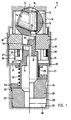
- FIG. 1 shows all parts of the detonator in their safety position and the right half of FIG. 1 shows these parts of the detonator at the moment a primer is pierced by an ignition pin.
- the igniter 9 has a front housing part 10 and a rear housing part 11, which are however only indicated incompletely and which are connected to one another in a manner not shown.
- the front housing part 10 has a cylindrical bore 12 in which there is a spherical or disk-shaped rotor 13.
- This rotor 13 contains a squib 14 which can be pierced by a firing pin 15.
- This ignition pin 15 is slidably guided in a bore 16 of a disc 17.
- the disc 17 is clamped between a shoulder 19 in the front housing part 10 and a sleeve 18 which is supported on a shoulder 20 in the rear housing part 11.
- the firing pin 15 is fastened to a hammer sleeve 21 which has a shoulder 22 in its central part and has a guide disk 23 at its rear end.
- the mentioned bushing 18, which is rigidly anchored in the rear housing part 11, has a bottom 24.
- a retaining spring 25 is supported on the one hand on the floor 24 and on the other hand on the guide disk 23 of the hammer sleeve 21 and strives to push the hammer sleeve 21 backwards, ie to push the firing pin 15 away from the squib 14.
- Inside the sleeve 18 there are a number of locking bodies 26 which, as shown in the left half of FIG.
- the soil igniter according to the invention shown in FIG. 3 differs from the soil igniter just described with reference to FIG. 1 by another inertial body 35.
- This inertial body 35 consists of a front cylindrical part 36, a central frustoconical part 37 and a rear cylindrical part 38 and is divided into four 90 ° sectors 35a, 35b, 35c, and 35d according to FIG.
- Fig. 3 four different positions of the inertial body 35 are shown. It is in its rearmost position on the left side of FIG. 3 and the inertial body 35 is in its foremost position on the right side of FIG. 3.
- two intermediate positions are indicated on the right side of FIG. 3, which are designated by 35-1 and 35-11.
- This inertial body 35 is located in a bore 30 of the igniter housing 10, 11, which is bounded by a rear, cylindrical section 32 of smaller diameter and a front, cylindrical section 33 of larger diameter, which are connected to one another via a conical surface 39. Furthermore, the bore 30 has a tapered shoulder 40 on which the inertial body 35 is supported with its frustoconical part 37 under the action of the swirl.
- the floor igniter according to the invention shown in FIG. 4 differs from the floor igniter described in FIG. 1 by another inertial body 135.
- This inertial body 135 consists of a front, slightly conical part 136, a central, frustoconical part 137, a third, slightly conical part 138 and a rear, frustoconical part 141 and is divided into four 90 ° sectors 35a, 35b, 35c and 35d according to FIG. 4 shows four different positions of the inertial body 135. It is in its rearmost position on the left side of FIG. 4 and in its foremost position on the right side of FIG. 3. In addition, two intermediate positions are indicated on the right side of FIG. 4, which are designated 135-1 and 135-11.
- This inertial body 135 is located in a bore 130 of the igniter housing 10, 11, which is delimited by a rear, slightly conical section 132 of smaller diameter and a front, slightly conical section 133 of larger diameter, which are connected to one another via a conical surface 139 . Furthermore, the bore 130 has a conical shoulder 140, on which the inertial body 135 is supported with its frustoconical part 137 under the action of the swirl.
Landscapes
- Engineering & Computer Science (AREA)
- General Engineering & Computer Science (AREA)
- Toys (AREA)
- Automotive Seat Belt Assembly (AREA)
- Air Bags (AREA)
- Coating By Spraying Or Casting (AREA)
Claims (5)
Applications Claiming Priority (4)
| Application Number | Priority Date | Filing Date | Title |
|---|---|---|---|
| CH111/86 | 1986-01-14 | ||
| CH11186 | 1986-01-14 | ||
| CH3060/86 | 1986-07-30 | ||
| CH306086 | 1986-07-30 |
Publications (2)
| Publication Number | Publication Date |
|---|---|
| EP0229302A1 EP0229302A1 (fr) | 1987-07-22 |
| EP0229302B1 true EP0229302B1 (fr) | 1989-04-19 |
Family
ID=25683547
Family Applications (1)
| Application Number | Title | Priority Date | Filing Date |
|---|---|---|---|
| EP86117026A Expired EP0229302B1 (fr) | 1986-01-14 | 1986-12-08 | Poids d'inertie pour fusée de base d'un projectile stabilisé par rotation |
Country Status (6)
| Country | Link |
|---|---|
| US (1) | US4723490A (fr) |
| EP (1) | EP0229302B1 (fr) |
| CA (1) | CA1269276A (fr) |
| DE (1) | DE3662946D1 (fr) |
| IL (1) | IL81185A (fr) |
| NO (1) | NO162314C (fr) |
Families Citing this family (2)
| Publication number | Priority date | Publication date | Assignee | Title |
|---|---|---|---|---|
| DE3827785A1 (de) * | 1988-08-16 | 1990-02-22 | Nico Pyrotechnik | Abstandszuender mit vorrohrsicherheit |
| DE19848356C2 (de) * | 1998-10-21 | 2001-09-13 | Rheinmetall W & M Gmbh | Zündnadel für Geschoßzünder mit einer mechanischen Übersetzung |
Family Cites Families (6)
| Publication number | Priority date | Publication date | Assignee | Title |
|---|---|---|---|---|
| NL238502A (fr) * | 1958-04-25 | |||
| CH585891A5 (fr) * | 1974-11-20 | 1977-03-15 | Oerlikon Buehrle Ag | |
| NO153441C (no) * | 1980-12-11 | 1986-03-19 | Junghans Gmbh Geb | Prosjektilsikring for roterende prosjektiler. |
| DE3049082C2 (de) * | 1980-12-24 | 1984-08-23 | Diehl GmbH & Co, 8500 Nürnberg | Sicherungseinrichtung für einen Zünder |
| DE3262029D1 (en) * | 1981-06-30 | 1985-03-07 | Oerlikon Buehrle Ag | Safety means for a fuze of a spin-stabilised projectile |
| NO148792C (no) * | 1981-09-21 | 1983-12-14 | Raufoss Ammunisjonsfabrikker | Sikringsanordning for rotasjonsprosjektil |
-
1986
- 1986-12-08 EP EP86117026A patent/EP0229302B1/fr not_active Expired
- 1986-12-08 DE DE8686117026T patent/DE3662946D1/de not_active Expired
- 1986-12-12 NO NO865033A patent/NO162314C/no unknown
- 1986-12-29 US US06/946,958 patent/US4723490A/en not_active Expired - Fee Related
-
1987
- 1987-01-02 CA CA000526611A patent/CA1269276A/fr not_active Expired - Lifetime
- 1987-01-07 IL IL81185A patent/IL81185A/xx not_active IP Right Cessation
Also Published As
| Publication number | Publication date |
|---|---|
| NO162314B (no) | 1989-08-28 |
| NO865033L (no) | 1987-07-15 |
| NO162314C (no) | 1989-12-06 |
| US4723490A (en) | 1988-02-09 |
| IL81185A0 (en) | 1987-08-31 |
| CA1269276A (fr) | 1990-05-22 |
| EP0229302A1 (fr) | 1987-07-22 |
| IL81185A (en) | 1991-11-21 |
| NO865033D0 (no) | 1986-12-12 |
| DE3662946D1 (en) | 1989-05-24 |
Similar Documents
| Publication | Publication Date | Title |
|---|---|---|
| DE2134945C3 (de) | Raketengeschoß mit Sekundärgeschossen | |
| DE2907308C2 (de) | Geschoß mit mindestens einem ausstoßbaren Tochtergeschoß | |
| DE1907315A1 (de) | Geschoss mit Hohlsprengladung | |
| DE2550093C3 (de) | Beharrungszünder für Drallgeschosse mit Selbstzerlegereinrichtung | |
| DE3737232A1 (de) | Uebungsgeschoss mit verkuerzter reichweite | |
| EP0068534A2 (fr) | Dispositif de sécurité pour la fusée d'un projectile stabilisé par rotation | |
| DE3149346C2 (fr) | ||
| DE1703501A1 (de) | Aufschlagzuender mit kippbarem Rotor fuer Drallgeschosse | |
| DE3119369C2 (de) | Beharrungszünder für Drallgeschosse mit Selbstzerlegereinrichtung | |
| DE642579C (de) | Mechanischer Zuender fuer Drallgeschosse mit kombinierter Aufschlag- und Zeitzerlegereinrichtung | |
| DE450061C (de) | Zuender mit Vorrichtung zum Verhindern des Rueckschlagens des Zuendstrahls | |
| DE720097C (de) | Aufschlagzuender | |
| EP0042957A2 (fr) | Fusée pour projectiles à rotation | |
| EP0229302A1 (fr) | Poids d'inertie pour fusée de base d'un projectile stabilisé par rotation | |
| DE562367C (de) | Zuender fuer Drallgeschosse | |
| DE2527339C3 (de) | Aufschlagzünder mit einer mittig in einem Schlagkörper eingesetzten Zündpille | |
| DE2842882C3 (de) | Aufschlagzünder mit einer Zündkapsel | |
| DE2008157C3 (de) | Hohlladung | |
| DE2149117A1 (de) | Geschosszuender | |
| DE1206761B (de) | Aufschlagzuender, insbesondere Bodenzuender, fuer explosive Drallgeschosse mit mechanischer Selbstzerlegervorrichtung | |
| DE2336880C2 (de) | Drallgeschoßzünder mit einer Selbstzerlegervorrichtung | |
| EP0139160B1 (fr) | Fusée à percussion pour missiles rotatifs | |
| EP0111198B1 (fr) | Fusée à percussion | |
| CH667527A5 (en) | Spin operated fuse for explosive shell - has auxiliary pin preventing return to safe position after operation of centrifugal elements | |
| DE4141082C2 (de) | Drallstabilisiertes Übungsgeschoß mit verkürzter Reichweite |
Legal Events
| Date | Code | Title | Description |
|---|---|---|---|
| PUAI | Public reference made under article 153(3) epc to a published international application that has entered the european phase |
Free format text: ORIGINAL CODE: 0009012 |
|
| AK | Designated contracting states |
Kind code of ref document: A1 Designated state(s): BE CH DE FR GB IT LI NL SE |
|
| 17P | Request for examination filed |
Effective date: 19870805 |
|
| 17Q | First examination report despatched |
Effective date: 19881004 |
|
| GRAA | (expected) grant |
Free format text: ORIGINAL CODE: 0009210 |
|
| AK | Designated contracting states |
Kind code of ref document: B1 Designated state(s): BE CH DE FR GB IT LI NL SE |
|
| GBT | Gb: translation of ep patent filed (gb section 77(6)(a)/1977) | ||
| REF | Corresponds to: |
Ref document number: 3662946 Country of ref document: DE Date of ref document: 19890524 |
|
| ET | Fr: translation filed | ||
| ITF | It: translation for a ep patent filed | ||
| PLBE | No opposition filed within time limit |
Free format text: ORIGINAL CODE: 0009261 |
|
| STAA | Information on the status of an ep patent application or granted ep patent |
Free format text: STATUS: NO OPPOSITION FILED WITHIN TIME LIMIT |
|
| 26N | No opposition filed | ||
| ITTA | It: last paid annual fee | ||
| PGFP | Annual fee paid to national office [announced via postgrant information from national office to epo] |
Ref country code: FR Payment date: 19921111 Year of fee payment: 7 |
|
| PGFP | Annual fee paid to national office [announced via postgrant information from national office to epo] |
Ref country code: CH Payment date: 19921116 Year of fee payment: 7 |
|
| PGFP | Annual fee paid to national office [announced via postgrant information from national office to epo] |
Ref country code: SE Payment date: 19921118 Year of fee payment: 7 |
|
| PGFP | Annual fee paid to national office [announced via postgrant information from national office to epo] |
Ref country code: GB Payment date: 19921119 Year of fee payment: 7 |
|
| PGFP | Annual fee paid to national office [announced via postgrant information from national office to epo] |
Ref country code: DE Payment date: 19921125 Year of fee payment: 7 |
|
| PGFP | Annual fee paid to national office [announced via postgrant information from national office to epo] |
Ref country code: BE Payment date: 19921126 Year of fee payment: 7 |
|
| PGFP | Annual fee paid to national office [announced via postgrant information from national office to epo] |
Ref country code: NL Payment date: 19921231 Year of fee payment: 7 |
|
| PG25 | Lapsed in a contracting state [announced via postgrant information from national office to epo] |
Ref country code: GB Effective date: 19931208 |
|
| PG25 | Lapsed in a contracting state [announced via postgrant information from national office to epo] |
Ref country code: SE Effective date: 19931209 |
|
| PG25 | Lapsed in a contracting state [announced via postgrant information from national office to epo] |
Ref country code: LI Effective date: 19931231 Ref country code: CH Effective date: 19931231 Ref country code: BE Effective date: 19931231 |
|
| BERE | Be: lapsed |
Owner name: WERKZEUGMASCHINENEFABRIK OERLIKON-BUHRLE A.G. Effective date: 19931231 |
|
| PG25 | Lapsed in a contracting state [announced via postgrant information from national office to epo] |
Ref country code: NL Effective date: 19940701 |
|
| GBPC | Gb: european patent ceased through non-payment of renewal fee |
Effective date: 19931208 |
|
| NLV4 | Nl: lapsed or anulled due to non-payment of the annual fee | ||
| PG25 | Lapsed in a contracting state [announced via postgrant information from national office to epo] |
Ref country code: FR Effective date: 19940831 |
|
| REG | Reference to a national code |
Ref country code: CH Ref legal event code: PL |
|
| PG25 | Lapsed in a contracting state [announced via postgrant information from national office to epo] |
Ref country code: DE Effective date: 19940901 |
|
| REG | Reference to a national code |
Ref country code: FR Ref legal event code: ST |
|
| EUG | Se: european patent has lapsed |
Ref document number: 86117026.4 Effective date: 19940710 |
|
| PG25 | Lapsed in a contracting state [announced via postgrant information from national office to epo] |
Ref country code: IT Free format text: LAPSE BECAUSE OF NON-PAYMENT OF DUE FEES;WARNING: LAPSES OF ITALIAN PATENTS WITH EFFECTIVE DATE BEFORE 2007 MAY HAVE OCCURRED AT ANY TIME BEFORE 2007. THE CORRECT EFFECTIVE DATE MAY BE DIFFERENT FROM THE ONE RECORDED. Effective date: 20051208 |