EP0229355A2 - Vorrichtung und Verfahren zur Durchführung von photometrischen Untersuchungen - Google Patents
Vorrichtung und Verfahren zur Durchführung von photometrischen Untersuchungen Download PDFInfo
- Publication number
- EP0229355A2 EP0229355A2 EP86117641A EP86117641A EP0229355A2 EP 0229355 A2 EP0229355 A2 EP 0229355A2 EP 86117641 A EP86117641 A EP 86117641A EP 86117641 A EP86117641 A EP 86117641A EP 0229355 A2 EP0229355 A2 EP 0229355A2
- Authority
- EP
- European Patent Office
- Prior art keywords
- light
- change
- changes
- intensity
- light detector
- Prior art date
- Legal status (The legal status is an assumption and is not a legal conclusion. Google has not performed a legal analysis and makes no representation as to the accuracy of the status listed.)
- Withdrawn
Links
Images

Classifications
-
- G—PHYSICS
- G01—MEASURING; TESTING
- G01N—INVESTIGATING OR ANALYSING MATERIALS BY DETERMINING THEIR CHEMICAL OR PHYSICAL PROPERTIES
- G01N21/00—Investigating or analysing materials by the use of optical means, i.e. using sub-millimetre waves, infrared, visible or ultraviolet light
- G01N21/75—Systems in which material is subjected to a chemical reaction, the progress or the result of the reaction being investigated
- G01N21/77—Systems in which material is subjected to a chemical reaction, the progress or the result of the reaction being investigated by observing the effect on a chemical indicator
- G01N21/82—Systems in which material is subjected to a chemical reaction, the progress or the result of the reaction being investigated by observing the effect on a chemical indicator producing a precipitate or turbidity
-
- G—PHYSICS
- G01—MEASURING; TESTING
- G01N—INVESTIGATING OR ANALYSING MATERIALS BY DETERMINING THEIR CHEMICAL OR PHYSICAL PROPERTIES
- G01N21/00—Investigating or analysing materials by the use of optical means, i.e. using sub-millimetre waves, infrared, visible or ultraviolet light
- G01N21/17—Systems in which incident light is modified in accordance with the properties of the material investigated
- G01N21/59—Transmissivity
-
- G—PHYSICS
- G01—MEASURING; TESTING
- G01N—INVESTIGATING OR ANALYSING MATERIALS BY DETERMINING THEIR CHEMICAL OR PHYSICAL PROPERTIES
- G01N2201/00—Features of devices classified in G01N21/00
- G01N2201/06—Illumination; Optics
- G01N2201/061—Sources
- G01N2201/0616—Ambient light is used
Definitions
- the invention consists of an apparatus which can be used for carrying out tests in which the result is expressed as changes in the phototransmittance of a solution to be analyzed.
- the apparatus can be used for qualitative, semi-quantitative or quantitative analyses in the liquid phase and according to the type of test the assay can be carried out either directly on top of the apparatus, on a separate test plate or well plate or in a cuvette or some similar vessel.
- the conditions and the sample concentration are usually chosen so that the changes occurring in light intensity correspond to those changes occurring in the concentrations of the reaction components as a function of time or alternatively the sample concentrations are chosen to lie between those of certain measurable standard solutions.
- the chosen system fulfills these conditions, it is said to obey the Lambert-Beer law, according to which the change in intensity of light passing through a solution is proportional to the concentration of absorbing units in the solution.
- Absorbance may alternatively be referred to as optical density (OD), or in some cases the transmittance of a liquid, i.e. the direct ratio between penetrating and non-penetrating light (I/I O ), may be used instead of absorbance.
- absorption is usually measured in the ultra-violet range (UV, 200 nm-400 nm), the visible range (400 nm-700 nm) or in the near infrared range (IR, 700 nm-900 nm).
- the light beam used in the measurement is usually arranged to be as nearly monochromatic as possible, using light-absorbing filters, slits or prisms if the ultimate source of light emits a polychromatic beam.
- the source of light may also be eg. light-emitting diodes or light produced be laser technology. In this case the light is sufficiently monochromatic without further treatment.
- the conditions and the sample concentration are usually chosen so that the changes in light intensity correspond to those changes which occur in the concentrations of the components of the reaction being measured, or in the size or number of aggregates, as a function of time or are concentration changes or changes in the number or size of aggregates between different liquids.
- Methods based on scattering are usually employed to measure the disintegration of macromolecules, aggregates, emulsions or suspensions or alternatively the formation of aggregates; eg. the agglutination reaction between the two components of an immunological pair, one of which may be attached to a carrier and the other in free solution in the liquid under examination.
- the Rayleigh scattering law is valid only when the particle size is smaller than the wavelength of the light. Under these conditions the scattering pattern is symmetrical. In the case of larger particles the scattering becomes asymmetrical and is referred to as Mie-scattering.
- the primary component of the apparatus is a light detector, on the top of which a chemical or immunochemical analysis is carried out.
- the solution to be assayed may be placed as such on the light detector or it may be placed on a separate test plate or measuring well plate or added to a cuvette.
- the apparatus may include the necessary analyzing units for carrying out the simultaneous measurement of several samples.
- One such unit is composed of at least one light detector, on the top of which the actual measurement is carried out.
- the unit may also contain a light detector on the top of which a control measurement is carried out.
- the unit may also include a light detector which monitors the light characteristics in the surrounding space.
- the apparatus may operate so that the same light detector may function in two or more modes at different times. Thus the same light detector may carry out several different measurements.
- the apparatus may be used to carry out kinetic measurements.
- the apparatus may carry out an initial zero measurement to compensate for the ambient light intensity.
- the apparatus uses external light as its source of light, so that the wavelength utilized is determined by that of the external light souce.
- the wavelength range may be defined by using eg. filters passing only monochromatic light of a certain fixed wavelength.
- the apparatus also includes the necessary controls and a suitable display showing either absorbance or concentration, either in relative units or numerically.
- the apparatus also includes a power souce, which may be eg. a solar cell, a battery or accumulator, an A/D converter or a comparator, a processing unit and a timer.
- Figure 1 presents the principle governing the measurement of light passing through a drop of sample liquid
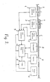
- Figure 2 presents a flow diagram of the apparatus carrying out the method as described in this invention.
- the measurement of light passing through a sample drop is presented as a cross-sectional diagram in Figure 1.
- the sample drop 1 is pipetted onto the top surface of a polymer sheet 2.
- the lower surface of the polymer sheet 2 is coated with a non-transmitting film 3 in which there is a hole 4 for the purpose of the measurement.
- the size of the hole 4 is dependent on the size and shape of the drop 1 and on the size of the light detector 5.
- the drop 1 must however completely cover the hole 4.
- a light detector 5 In line with the hole 4, below the covering sheets 2 and 3, is a light detector 5, which measures the amount of light passing through the hole 4 in the film 3.
- the light detector may be eg. a light resistor, a photodiode or a phototransistor.
- the light entering the light detector 5 may be filtered with the filter 6.
- the amount 0 ⁇ I of light entering the light detector 5 is proportional to the difference between the amount 0 ⁇ I of light entering the sample drop 1 from the environment and the amount 0 ⁇ S of light leaving the drop to the environment or surrounding matrix due to scattering, absorption, reflection and refraction.
- the light detector can be used to detect changes in the size and number of particles in the sample drop or altered light intensity due to absorption.
- the signal processing circuits 7 of the light detector 5 are protected by a plastic film 8.
- the apparatus may include three light detectors with different functions.
- the light detector 1 measures light passing throug the sample drop 2.
- the sample drop 2 contains a reagent and the sample.
- the light detector 3 measures light passing through the reference drop 4 which may contain eg. a negative control reagent.
- the light detector 5 measures the illumination of the surrounding environment directly.
- the electrical energy required for operation of the apparatus may also be obtained from an internal source such as a battery or accumulator. Operational readiness is indicated on the display 7. This indication is at the same time an indication of the sufficiency of illumination and of the state of charge of the possible battery or accumulator.
- the measurement is started by pressing the zero calibration button 8, after which the display 7 is zeroed and the signal entering the apparatus from each light detector is converted to digital form in the A/D-converter 9 and transferred to the memory in the processing unit 10. Simultaneously, the timer 11 is started. When the timer 11 has measured a time T, the signals transmitted by the light detectors are again transferred to the processing unit 10. On the basis of the two measurement results given by the light detector 5 the change d0 ⁇ T in ambient illumination during the time T is calculated. Similarly, the signals transmitted by the light detectors 1 and 3 are used to calculate the changes d0 ⁇ N and d0 ⁇ R occurring in the light passing through the sample drop 2 and the reference drop 4 over the same time period T.
- the signal corresponding to the change d0 ⁇ N in the light passing through the sample drop 2 is first corrected for the change d0 ⁇ T occurring in the ambient illumination and the change d0 ⁇ R occurring in the reference drop 4, and then scaled and taken to the display 7. If it is only required to indicate whether the change in the sample drop 2 exceeds a certain threshold value, the A/D converter is a comparator, i.e. a single-bit A/D-conversion is carried out.
- the test is carried out on a table, above which is a 40 W fluorescent strip lamp at a distance of 60 cm from the photodiodes functioning as detector.
- a table above which is a 40 W fluorescent strip lamp at a distance of 60 cm from the photodiodes functioning as detector.
- To the cylindrical glass-bottomed vessel on top of the photodiode are added different concentrations of solutions of the reaction products of o-phenylenediamine and peroxidase enzyme in a 2 mm layer.
Landscapes
- Physics & Mathematics (AREA)
- Chemical & Material Sciences (AREA)
- Biochemistry (AREA)
- General Health & Medical Sciences (AREA)
- Plasma & Fusion (AREA)
- Health & Medical Sciences (AREA)
- Life Sciences & Earth Sciences (AREA)
- Analytical Chemistry (AREA)
- Engineering & Computer Science (AREA)
- Chemical Kinetics & Catalysis (AREA)
- General Physics & Mathematics (AREA)
- Immunology (AREA)
- Pathology (AREA)
- Investigating Or Analysing Materials By Optical Means (AREA)
- Investigating Or Analysing Materials By The Use Of Chemical Reactions (AREA)
- Photometry And Measurement Of Optical Pulse Characteristics (AREA)
Applications Claiming Priority (2)
| Application Number | Priority Date | Filing Date | Title |
|---|---|---|---|
| FI860042A FI860042L (fi) | 1985-10-01 | 1986-01-06 | Anordning och foerfarande foer genomfoerande av fotometrisk analys. |
| FI860042 | 1986-01-06 |
Publications (2)
| Publication Number | Publication Date |
|---|---|
| EP0229355A2 true EP0229355A2 (de) | 1987-07-22 |
| EP0229355A3 EP0229355A3 (de) | 1988-01-07 |
Family
ID=8521916
Family Applications (1)
| Application Number | Title | Priority Date | Filing Date |
|---|---|---|---|
| EP86117641A Withdrawn EP0229355A3 (de) | 1986-01-06 | 1986-12-18 | Vorrichtung und Verfahren zur Durchführung von photometrischen Untersuchungen |
Country Status (2)
| Country | Link |
|---|---|
| EP (1) | EP0229355A3 (de) |
| JP (1) | JPS62289751A (de) |
Family Cites Families (7)
| Publication number | Priority date | Publication date | Assignee | Title |
|---|---|---|---|---|
| US4135818A (en) * | 1975-01-22 | 1979-01-23 | Bio/Data Corporation | Platelet aggregation monitoring device |
| DE7534573U (de) * | 1975-10-31 | 1977-10-06 | Merck Patent Gmbh, 6100 Darmstadt | Vorrichtung zur analytischen bestimmung von substanzen in loesung |
| FI56905C (fi) * | 1978-02-28 | 1980-04-10 | Osmo A Suovaniemi | Foerfarande och anordning foer automatisk maetning av agglutinationsprov t ex i spektrofotometer adsoptionsfotometer fluorometer eller nefelometer |
| JPS57110197A (en) * | 1980-12-29 | 1982-07-08 | Fuji Photo Film Co Ltd | Determination of hydrogen peroxide |
| JPS5895248A (ja) * | 1981-11-02 | 1983-06-06 | Olympus Optical Co Ltd | 粒子凝集判定用容器およびこの容器を用いる粒子凝集判定方法 |
| JPS61501162A (ja) * | 1983-11-21 | 1986-06-12 | ラブシステムズ オイ | 凝集反応結果の決定方法 |
| FI853783L (fi) * | 1985-10-01 | 1987-04-02 | Orion Yhtymae Oy | Anordning och foerfarande foer laesning av agglutinationstestresultat. |
-
1986
- 1986-12-18 EP EP86117641A patent/EP0229355A3/de not_active Withdrawn
-
1987
- 1987-01-06 JP JP24687A patent/JPS62289751A/ja active Pending
Also Published As
| Publication number | Publication date |
|---|---|
| JPS62289751A (ja) | 1987-12-16 |
| EP0229355A3 (de) | 1988-01-07 |
Similar Documents
| Publication | Publication Date | Title |
|---|---|---|
| US4125372A (en) | Method and device for testing liquids | |
| CN1961205B (zh) | 具有用于对多个分析物进行化学分析的可置换元件的手持式装置 | |
| US6195158B1 (en) | Apparatus and method for rapid spectrophotometric pre-test screen of specimen for a blood analyzer | |
| JP2916637B2 (ja) | 拡散分光反射率の測定装置 | |
| NO750639L (de) | ||
| JPS5925460B2 (ja) | ネフェロメトリック・イムノアッセイ法及び装置 | |
| US4988630A (en) | Multiple beam laser instrument for measuring agglutination reactions | |
| WO1983000931A1 (en) | Method and apparatus for detecting sample fluid | |
| US4659229A (en) | Readhead with reduced height sensitivity | |
| EP0223427B1 (de) | Verfahren und Apparat zur Bestimmung des Antikörperinhalts von Blut | |
| EP0229355A2 (de) | Vorrichtung und Verfahren zur Durchführung von photometrischen Untersuchungen | |
| EP0110262A2 (de) | Optischer Lesekopf | |
| CN214408685U (zh) | 一种基于全反射折光法的食品分析仪 | |
| JPH0843390A (ja) | 免疫測定方法及びその装置 | |
| EP0433629B1 (de) | Verfahren zur quantitativen und qualitativen Bestimmung von Antikörpern gegen bakterielle Antigene mittels photometrischer Messung der Agglutination | |
| JPH07113635B2 (ja) | 免疫反応におけるプロゾ−ン判定方法 | |
| JPS6128866A (ja) | 光強度ゆらぎを用いる免疫反応の測定方法および装置 | |
| Akhila et al. | A Review Article on Nepheloturbidometry | |
| JPS61173138A (ja) | 光強度ゆらぎによる免疫反応測定方法 | |
| JPS6052761A (ja) | 電解質測定方法 | |
| CN102539327A (zh) | 一种用于干式化学检测的积分球装置 | |
| Shishkin et al. | A portable reflectometric photometer for quantitative enzyme immunoassay | |
| RU2188403C1 (ru) | Мини-рефлектометр-колориметр для анализа жидких и газообразных сред реагентными индикаторными бумажными тестами | |
| JPS60125541A (ja) | 検液の濁り度検出方法 | |
| JPS61173139A (ja) | 光強度ゆらぎによる免疫反応測定方法 |
Legal Events
| Date | Code | Title | Description |
|---|---|---|---|
| PUAI | Public reference made under article 153(3) epc to a published international application that has entered the european phase |
Free format text: ORIGINAL CODE: 0009012 |
|
| AK | Designated contracting states |
Kind code of ref document: A2 Designated state(s): AT BE CH DE ES FR GB GR IT LI NL SE |
|
| PUAL | Search report despatched |
Free format text: ORIGINAL CODE: 0009013 |
|
| AK | Designated contracting states |
Kind code of ref document: A3 Designated state(s): AT BE CH DE ES FR GB GR IT LI NL SE |
|
| RHK1 | Main classification (correction) |
Ipc: G01N 21/82 |
|
| STAA | Information on the status of an ep patent application or granted ep patent |
Free format text: STATUS: THE APPLICATION IS DEEMED TO BE WITHDRAWN |
|
| 18D | Application deemed to be withdrawn |
Effective date: 19880708 |
|
| RIN1 | Information on inventor provided before grant (corrected) |
Inventor name: PORAMO, RISTO A.A. Inventor name: KAHMA, KAUKO ILMARI Inventor name: NISKANEN, AIMO JUHANI Inventor name: VAINIO, ATTE OLAVI Inventor name: LEKKALA, JUKKA OLAVI, Inventor name: JOKI, HARRI KALEVI |