EP0229418A2 - Speiseeisbereiter mit einem die Eismasse aufnehmenden topfförmigen Behälter - Google Patents
Speiseeisbereiter mit einem die Eismasse aufnehmenden topfförmigen Behälter Download PDFInfo
- Publication number
- EP0229418A2 EP0229418A2 EP86202225A EP86202225A EP0229418A2 EP 0229418 A2 EP0229418 A2 EP 0229418A2 EP 86202225 A EP86202225 A EP 86202225A EP 86202225 A EP86202225 A EP 86202225A EP 0229418 A2 EP0229418 A2 EP 0229418A2
- Authority
- EP
- European Patent Office
- Prior art keywords
- ice
- scraping
- cold
- pot
- ice cream
- Prior art date
- Legal status (The legal status is an assumption and is not a legal conclusion. Google has not performed a legal analysis and makes no representation as to the accuracy of the status listed.)
- Granted
Links
Images
Classifications
-
- A—HUMAN NECESSITIES
- A23—FOODS OR FOODSTUFFS; TREATMENT THEREOF, NOT COVERED BY OTHER CLASSES
- A23G—COCOA; COCOA PRODUCTS, e.g. CHOCOLATE; SUBSTITUTES FOR COCOA OR COCOA PRODUCTS; CONFECTIONERY; CHEWING GUM; ICE-CREAM; PREPARATION THEREOF
- A23G9/00—Frozen sweets, e.g. ice confectionery, ice-cream; Mixtures therefor
- A23G9/04—Production of frozen sweets, e.g. ice-cream
- A23G9/08—Batch production
- A23G9/12—Batch production using means for stirring the contents in a non-moving container
Definitions
- the invention relates to an ice cream maker with a pot-shaped container receiving an ice mass, of which at least part of the wall surface is thermally conductive with a medium that supplies the cold required for ice formation, in particular a cold-storing medium, and in which one of an electric motor a reduction gear driven scraping and stirring tool moves.
- an ice cream machine which is provided with a pot-shaped container for receiving the ice cream.
- a cold cartridge can be inserted into the container.
- a scraper and agitator is provided which is set in rotation by means of an electric motor and a gear and scrapes over the top of the cold cartridge and at the same time stirs the ice mass in the container.
- Ice mass which is cooled from the cold cartridge, freeze on the surface of the cold cartridge.
- the object is achieved in that the scraping and stirring speed is set by means of the reduction gear to a speed range between 18 and 30 U / min and that the heat transport is adjusted so that the thickness of the ice layer formed between two scraping cycles is not greater than Is 2 mm.
- the cold-storing medium is housed in a cold cartridge for easier handling and to increase mobility.
- the speed is preferably set to 20 to 26 rpm. With such a circulating speed of the scraping and stirring tool, the ice cream mass has enough time to freeze on the cold-emitting surface in the container, and the freezing is still so limited that the scraping and stirring tool can still scrape off the frozen ice cream. With such a suitable coordination, good ice cream quality results within a short time. Such an ice thickness can just perfectly be removed from the scraping and stirring tool.
- the output power of the drive motor is designed to be less than 10 W, preferably 5 W, for a pot or tool diameter of approximately 16 to 20 cm.
- the previously specified condition of freezing on the cold-emitting surface makes it possible to reduce the drive power of the drive motor.
- the use of a two-pole single-phase synchronous motor as the drive motor is then suitable for such outputs.
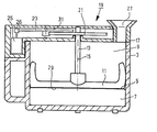
- the ice cream maker shown has a pot-shaped, thermally insulated container 3.
- the bottom 5 of the container 3 serves as a thermal transition surface for thermal energy.
- Below the base 5 there is, for example, a latent heat storage medium 7 in a cold cartridge 6, which is accommodated, for example, in a cold cartridge.
- the pot bottom 5 can also be cooled in a different way.
- a scraping and stirring tool 11 is arranged in the ice-making chamber 9 within the pot-shaped container 3. This scraping and stirring tool 11 is rotatable by means of a shaft 13.
- the shaft axis is denoted by 15.
- a lid 19, in which the shaft 13 is mounted, can be placed on the top 17 of the pot-shaped container 3.
- the shaft 13 also carries a gear 21 which meshes with an intermediate gear 23 which is driven by a single-phase synchronous motor 25 via a pinion 26.
- a filling funnel 27 is provided on the lid 19, through which a liquid ice cream mass can be filled into the container interior 9.
- the scraping and stirring tool 11 scrapes with its scraping surface 29 over the container bottom 5.
- ice mass which freezes to the bottom surface is scraped off and stirred into the remaining ice mass inside the container interior 9.
- scraping and stirring it is important not to scrape off the ice that is setting up too quickly, so that the ice build-up is given a certain calm.
- the ice deposit must not become too thick, so that the motor is then overloaded as a result of excessive resistance.
- scraping off too quickly generates too much thermal energy, which has to be compensated for again by removing heat from the cooling medium.
- the transmission ratio between the rotational movement of the motor shaft 31 and the tool shaft 13 is therefore chosen such that the scraping and diverter tool rotates in a speed range between 18 and 35 rpm. Speeds between 20 and 26 rpm are preferred.
- the heat transport through the container base 5 is adjusted so that the thickness of the ice layer that forms is kept less than about 2 mm between two scraping cycles.
- the output power of the drive motor can be designed for a pot or tool diameter of approximately 16 to 20 cm to be less than 10 W, preferably 5 W. This makes it possible, for example, to use a low-loss two-pole single-phase synchronous motor as the drive motor, which itself generates only little heat and which therefore does not hinder the production of ice by heat transport.
Landscapes
- Engineering & Computer Science (AREA)
- Manufacturing & Machinery (AREA)
- Life Sciences & Earth Sciences (AREA)
- Chemical & Material Sciences (AREA)
- Food Science & Technology (AREA)
- Polymers & Plastics (AREA)
- Confectionery (AREA)
- Food-Manufacturing Devices (AREA)
Abstract
Description
- Die Erfindung bezieht sich auf einen Speiseeisbereiter mit einem eine Eismasse aufnehmenden topfförmigen Behälter, von dem wenigstens ein Teil der Wandoberfläche wärmeleitend ist mit einem Medium, das die zur Eisbildung benötigte Kälte liefert, insbesondere ein kältespeicherndes Medium, und in dem sich ein von einem Elektromotor über ein Untersetzungsgeetriebe angetriebenes Schab- und Rührwerkzeug bewegt.
- Aus der DE-OS 28 31 592 ist eine Speiseeismaschine bekannt, die mit einem topfförmigen Behälter zur Aufnahme der Eismasse versehen ist. In den Behälter ist eine Kältepatrone einlegbar. Es ist ein Schab- und Rührwerk vorgesehen, das mittels eines Elektromotors und eines Getriebes in Drehung versetzt wird und dabei über die Oberseite der Kältepatrone hinwegschabt und gleichzeitig die Eismasse im Behälter rührt.
- Für eine gute und zügige Speiseeisbereitung ist ein genügendes Anfrieren der Eismasse an der kälteabgebenden Fläche zwischen zwei Abschabezyklen wichtig. Ist die Umlaufgeschwindigkeit zu groß, dann ist eine verstärkte Kältezufuhr erforderlich, um die Eismasse, die aus der Kältepatrone gekühlt wird, an der Oberfläche der Kältepatrone zum Anfrieren zu bringen.
- Aus der US-PS 22 84 907 ist ein Gerät bekannt, das mit Eisbrocken gekühlt wird und bei dem der Schaber mit 25 U/min umläuft. Die Eisbrocken bewirken nur eine mäßige Wärmezufuhr zum Eisbereitungsbehälter, weshalb in diesem Fall die Drehgeschwindigkeit unkritisch ist.
- Eismasse, die aus der Kältepatrone gekühlt wird, an der Oberfläche der Kältepatrone zum Anfrieren zu bringen.
- Es ist Aufgabe der Erfindung, einen Speiseeisbereiter zu schaffen, der in einem für die Eisbereitung günstigen Verhältnis von Anfrierdicke des Speiseeises und Abschabgeschwindigkeit arbeitet.
- Die gestellte Aufgabe ist erfindungsgemäß dadurch gelöst, daß die Schab- und Rührgeschwindigkeit mittels des Untersetzungsgetriebes eingestellt ist auf einen Drehzahlbereich zwischen 18 und 30 U/min und daß der Wärmetransport darauf abgestimmt ist, daß die Dicke der sich bildenden Eisschicht zwischen zwei Abschabezyklen nicht größer als 2 mm ist. Das kältespeichernde Medium ist dabei zur erleichterten Handhabung und zur Vergrößerung der ' Mobilität in einer Kältepatrone untergebracht. Vorzugsweise ist die Drehzahl eingestellt auf 20 bis 26 U/min. Bei einer derartigen Umlaufgeschwindigkeit des Schab- und Rührwerkzeuges hat die Speiseeismasse genügend Zeit, an der kälteabgebenden Fläche im Behälter anzufrieren, und das Anfrieren ist dennoch so begrenzt, daß das Schab- und Rührwerkzeug die angefrorene Eismasse noch einwandfrei abschaben kann. Bei derartig passender Abstimmung ergibt sich innerhalb kurzer Zeit eine gute Speiseeisqualität. Eine solche Eisdicke kann gerade noch von dem Schab- und Rührwerkzeug einwandfrei abgezogen werden.
- Nach einer weiteren Ausgestaltung der Erfindung ist vorgesehen, daß die abgegebene Leistung des Antriebsmotors bei einem Topf- bzw. Werkzeugdurchmesser von ca. 16 bis 20 cm kleiner als 10 W, vorzugsweise 5 W, ausgelegt ist. Die zuvor angegebene Bedingung des Anfrierens an der kälteabgebenden Fläche ermöglicht es, die Antriebsleistung des Antriebsmotors herabzusetzen. Für solche Leistungen eignet sich dann der Einsatz eines zweipoligen Einphasensynchronmotors als Antriebsmotor.
- Die Erfindung wird anhand des in der Zeichnung dargestellten Ausführungsbeispieles näher erläutert.
- Der dargestellte Speiseeisbereiter weist einen topfförmigen, thermisch isolierten Behälter 3 auf. Der Boden 5 des Behälters 3 dient als thermische Übergangsfläche für Wärmeenergie. Unterhalb des Bodens 5 befindet sich beispielsweise in einer Kältepatrone 6 ein Latent-Wärmespeichermedium 7, das beispielsweise in einer Kältepatrone untergebracht ist. Der Topfboden 5 kann aber auch auf andere Art und Weise gekühlt werden.
- Im Eisbereitungsraum 9 innerhalb des topfförmigen Behälters 3 ist ein Schab- und Ruhrwerkzeug 11 angeordnet. Dieses Schab- und Rührwerkzeug 11 ist mittels einer Welle 13 drehbar. Die Wellenachse ist mit 15 bezeichnet.
- Auf die Oberseite 17 des topfförmigen Behälters 3 ist ein Deckel 19 aufsetzbar, in dem die Welle 13 gelagert ist. Die Welle 13 trägt auch ein Zahnrad 21, das mit einem Zwichenzahnrad 23 kämmt, das von einem Einphasensynchronmotor 25 über ein Ritzel 26 angetrieben wird. Am Deckel 19 ist ein Einfülltrichter 27 vorgesehen, durch den eine flüssige Speiseeismasse in das Behälterinnere 9 einfüllbar ist.
- Das Schab- und Rührwerkzeug 11 schabt mit seiner Schabefläche 29 über den Behälterboden 5 hinweg. Bei dem Entlangschaben über die Bodenfläche 5 wird Eismasse, die an der Bodenfläche anfriert, abgeschabt und in die übrige Eismasse innerhalb des Behälterinnenraumes 9 hineingerührt. Es kommt bei dem Abschaben und Umrühren darauf an, das sich ansetzende Eis nicht zu rasch abzuschaben, damit dem Eisansatz eine gewisse Ruhe vergönnt ist.
- Andererseits darf der Eisansatz nicht zu dick werden, so daß der Motor dann infolge zu hohen Widerstandes überlastet wird. Insbesondere ein zu rasches Abschaben erzeugt zu viel Wärmeenergie, die erst wieder durch Wärmeentzug aus dem Kältemedium ausgeglichen werden muß. Das Übersetzungsverhältnis zwischen der Umlaufbewegung der Motorwelle 31 und der Werkzeugwelle 13 ist deshalb so gewählt, daß das Schab- und Ruhrwerkzeug in einem Drehzahlbereich zwischen 18 und 35 U/min umläuft. Bevorzugt sind dabei Drehzahlen zwischen 20 und 26 U/min. In diesem Fall ist der Wärmetransport durch den Behälterboden 5 so abgestimmt, daß die Dicke der sich bildenden Eisschicht zwischen zwei Abschabzyklen kleiner als etwa 2 mm gehalten wird. In einem solchen Fall kann die abgegebene Leistung des Antriebsmotors bei einem Topf- bzw. Werkzeugdurchmesser von ca. 16 bis 20 cm auf kleiner als 10 W, vorzugsweise auf 5 W, ausgelegt sein. Hierdurch wird es möglich, als Antriebsmotor beispielsweise einen verlustarmen zweipoligen Einphasensynchronmotor einzusetzen, der selbst nur wenig Wärme entwickelt und der deshalb die Eisbereitung wärmetransportmäßig nicht behindert.
Claims (5)
Applications Claiming Priority (2)
| Application Number | Priority Date | Filing Date | Title |
|---|---|---|---|
| DE3544671 | 1985-12-18 | ||
| DE3544671A DE3544671C1 (de) | 1985-12-18 | 1985-12-18 | Speiseeisbereiter mit einem die Eismasse aufnehmenden topffoermigen Behaelter |
Publications (3)
| Publication Number | Publication Date |
|---|---|
| EP0229418A2 true EP0229418A2 (de) | 1987-07-22 |
| EP0229418A3 EP0229418A3 (en) | 1988-05-04 |
| EP0229418B1 EP0229418B1 (de) | 1992-03-18 |
Family
ID=6288687
Family Applications (1)
| Application Number | Title | Priority Date | Filing Date |
|---|---|---|---|
| EP86202225A Expired - Lifetime EP0229418B1 (de) | 1985-12-18 | 1986-12-10 | Speiseeisbereiter mit einem die Eismasse aufnehmenden topfförmigen Behälter |
Country Status (3)
| Country | Link |
|---|---|
| EP (1) | EP0229418B1 (de) |
| DE (2) | DE3544671C1 (de) |
| ES (1) | ES2030660T3 (de) |
Cited By (1)
| Publication number | Priority date | Publication date | Assignee | Title |
|---|---|---|---|---|
| EP0423898A3 (en) * | 1989-10-20 | 1991-07-17 | Bravo S.P.A. | Programmable electronic control system for machines for the production of pasty foodstuffs, especially machines for making ice-cream |
Families Citing this family (4)
| Publication number | Priority date | Publication date | Assignee | Title |
|---|---|---|---|---|
| DE3544671C1 (de) * | 1985-12-18 | 1986-11-13 | Philips Patentverwaltung Gmbh, 2000 Hamburg | Speiseeisbereiter mit einem die Eismasse aufnehmenden topffoermigen Behaelter |
| AT386321B (de) * | 1986-01-16 | 1988-08-10 | Philips Nv | Mischwerkzeug fuer eine speiseeismaschine |
| DE4239252A1 (de) * | 1992-11-21 | 1994-02-10 | Braun Ag | Haushaltsgerät zum Herstellen von Speiseeis |
| JPH09507126A (ja) * | 1994-10-12 | 1997-07-22 | フィリップス エレクトロニクス ネムローゼ フェンノートシャップ | アイスクリーム製造装置 |
Family Cites Families (8)
| Publication number | Priority date | Publication date | Assignee | Title |
|---|---|---|---|---|
| FR1252191A (fr) * | 1959-11-17 | 1961-01-27 | Agitateur électrique pour casserole agitant les aliments en cours de cuisson | |
| US3985347A (en) * | 1974-07-26 | 1976-10-12 | Doyel John S | Ice cream machine |
| CH624278A5 (de) * | 1977-09-26 | 1981-07-31 | M & F Engineering Ag | |
| US4417506A (en) * | 1981-09-23 | 1983-11-29 | Housewares Research Associates | Home cooking appliance |
| GB2144208B (en) * | 1983-06-14 | 1987-07-22 | Nippon Light Metal Co | Device for making frozen confections |
| IT8323448V0 (it) * | 1983-11-03 | 1983-11-03 | Bravo Spa | Macchina polivalente per laproduzione di gelato e di granita. |
| DK351684A (da) * | 1984-02-29 | 1985-08-30 | Baek Holding Aps P E | Termofrysebeholder, navnlig til en maskine til fremstilling af frosne desserter |
| DE3544671C1 (de) * | 1985-12-18 | 1986-11-13 | Philips Patentverwaltung Gmbh, 2000 Hamburg | Speiseeisbereiter mit einem die Eismasse aufnehmenden topffoermigen Behaelter |
-
1985
- 1985-12-18 DE DE3544671A patent/DE3544671C1/de not_active Expired
-
1986
- 1986-12-10 DE DE8686202225T patent/DE3684441D1/de not_active Expired - Lifetime
- 1986-12-10 ES ES198686202225T patent/ES2030660T3/es not_active Expired - Lifetime
- 1986-12-10 EP EP86202225A patent/EP0229418B1/de not_active Expired - Lifetime
Cited By (1)
| Publication number | Priority date | Publication date | Assignee | Title |
|---|---|---|---|---|
| EP0423898A3 (en) * | 1989-10-20 | 1991-07-17 | Bravo S.P.A. | Programmable electronic control system for machines for the production of pasty foodstuffs, especially machines for making ice-cream |
Also Published As
| Publication number | Publication date |
|---|---|
| EP0229418B1 (de) | 1992-03-18 |
| DE3544671C1 (de) | 1986-11-13 |
| DE3684441D1 (de) | 1992-04-23 |
| ES2030660T3 (es) | 1992-11-16 |
| EP0229418A3 (en) | 1988-05-04 |
Similar Documents
| Publication | Publication Date | Title |
|---|---|---|
| DE3119971C2 (de) | ||
| DE212022000435U1 (de) | Mikropüriermaschine mit feststehenden Motoren | |
| CA1283654C (en) | Mixer tool for an ice-cream maker | |
| US4696166A (en) | Ice-cream maker | |
| EP0351917A1 (de) | Kleines elektrisches Haushaltsgerät zur Herstellung von Speisen durch rührendes Mischen | |
| DE3486374T2 (de) | Eiserzeugungsmaschine. | |
| EP2179232A2 (de) | Vorrichtung zum erzeugen von eiswürfeln, kälteapparat mit dieser art vorrichtung und verfahren zum erzeugen von eiswürfeln | |
| EP0229418A2 (de) | Speiseeisbereiter mit einem die Eismasse aufnehmenden topfförmigen Behälter | |
| DE202008014427U1 (de) | Vorrichtung zum Herstellen von Eisstücken und Eisstückespender | |
| DE69808693T2 (de) | Maschine zum Herstellen von gefrorenen Getränken, insbesondere Brucheis oder Sorbets | |
| EP0031134A2 (de) | Vorrichtung zur kontinuierlichen Kristallisation | |
| JPS6222553A (ja) | アイシング製造方法 | |
| CN209997513U (zh) | 一种耐火材料生产用原料搅拌机 | |
| DE2225460B2 (de) | Vorrichtung zur bereitung und ausgabe von gefrorenen, erfrischungsprodukten und gekuehlten getraenken | |
| DE10048535A1 (de) | Küchenmaschine mit einem Rührgefäß sowie Verfahren zur Herstellung von Speiseeis | |
| DE2916310A1 (de) | Einrichtung zur kuehlung von fluessigkeiten, insbesondere auf temperaturen unterhalb deren erstarrungspunktes | |
| EP0006219A1 (de) | Verfahren und Vorrichtung zur Speicherung von Wärmeenergie | |
| JPH0655050A (ja) | 複軸混和装置 | |
| DE102020117190A1 (de) | Eisbereitungsvorrichtung für ein Haushalts-Kühlgerät sowie Wechseleinheit hierfür | |
| DE844748C (de) | Speiseeisbereiter | |
| DE2654674C3 (de) | Eismaschine'insbesondere für den Hausgebrauch | |
| CN214106563U (zh) | 一种农用化肥混合装置 | |
| DE1501195C (de) | Verfahren und Vorrichtung zur Her stellung von Brei halbgefrorener Kon sistenz | |
| DE7233649U (de) | Eismaschine | |
| CN110657613A (zh) | 一种低温-40—-50℃以下的化工流体冰制冰机 |
Legal Events
| Date | Code | Title | Description |
|---|---|---|---|
| PUAI | Public reference made under article 153(3) epc to a published international application that has entered the european phase |
Free format text: ORIGINAL CODE: 0009012 |
|
| AK | Designated contracting states |
Kind code of ref document: A2 Designated state(s): DE ES FR GB IT NL |
|
| RAP1 | Party data changed (applicant data changed or rights of an application transferred) |
Owner name: N.V. PHILIPS' GLOEILAMPENFABRIEKEN Owner name: PHILIPS PATENTVERWALTUNG GMBH |
|
| ITCL | It: translation for ep claims filed |
Representative=s name: ING. A. GIAMBROCONO & C. S.R.L. |
|
| PUAL | Search report despatched |
Free format text: ORIGINAL CODE: 0009013 |
|
| AK | Designated contracting states |
Kind code of ref document: A3 Designated state(s): DE ES FR GB IT NL |
|
| 17P | Request for examination filed |
Effective date: 19881021 |
|
| 17Q | First examination report despatched |
Effective date: 19900322 |
|
| GRAA | (expected) grant |
Free format text: ORIGINAL CODE: 0009210 |
|
| AK | Designated contracting states |
Kind code of ref document: B1 Designated state(s): DE ES FR GB IT NL |
|
| PG25 | Lapsed in a contracting state [announced via postgrant information from national office to epo] |
Ref country code: NL Effective date: 19920318 |
|
| REF | Corresponds to: |
Ref document number: 3684441 Country of ref document: DE Date of ref document: 19920423 |
|
| ITF | It: translation for a ep patent filed | ||
| GBT | Gb: translation of ep patent filed (gb section 77(6)(a)/1977) | ||
| ET | Fr: translation filed | ||
| NLV1 | Nl: lapsed or annulled due to failure to fulfill the requirements of art. 29p and 29m of the patents act | ||
| PLBE | No opposition filed within time limit |
Free format text: ORIGINAL CODE: 0009261 |
|
| STAA | Information on the status of an ep patent application or granted ep patent |
Free format text: STATUS: NO OPPOSITION FILED WITHIN TIME LIMIT |
|
| 26N | No opposition filed | ||
| ITTA | It: last paid annual fee | ||
| ITPR | It: changes in ownership of a european patent |
Owner name: CAMBIO RAGIONE SOCIALE;PHILIPS ELECTRONICS N.V. |
|
| REG | Reference to a national code |
Ref country code: FR Ref legal event code: CD |
|
| REG | Reference to a national code |
Ref country code: ES Ref legal event code: PC2A Owner name: PHILIPS ELECTRONICS N.V. |
|
| REG | Reference to a national code |
Ref country code: FR Ref legal event code: CD |
|
| REG | Reference to a national code |
Ref country code: ES Ref legal event code: PC2A |
|
| PGFP | Annual fee paid to national office [announced via postgrant information from national office to epo] |
Ref country code: ES Payment date: 20001219 Year of fee payment: 15 |
|
| PGFP | Annual fee paid to national office [announced via postgrant information from national office to epo] |
Ref country code: GB Payment date: 20001220 Year of fee payment: 15 |
|
| PGFP | Annual fee paid to national office [announced via postgrant information from national office to epo] |
Ref country code: FR Payment date: 20001226 Year of fee payment: 15 |
|
| PGFP | Annual fee paid to national office [announced via postgrant information from national office to epo] |
Ref country code: DE Payment date: 20010214 Year of fee payment: 15 |
|
| PG25 | Lapsed in a contracting state [announced via postgrant information from national office to epo] |
Ref country code: GB Free format text: LAPSE BECAUSE OF NON-PAYMENT OF DUE FEES Effective date: 20011210 |
|
| REG | Reference to a national code |
Ref country code: GB Ref legal event code: IF02 |
|
| PG25 | Lapsed in a contracting state [announced via postgrant information from national office to epo] |
Ref country code: DE Free format text: LAPSE BECAUSE OF NON-PAYMENT OF DUE FEES Effective date: 20020702 |
|
| GBPC | Gb: european patent ceased through non-payment of renewal fee |
Effective date: 20011210 |
|
| PG25 | Lapsed in a contracting state [announced via postgrant information from national office to epo] |
Ref country code: FR Free format text: LAPSE BECAUSE OF NON-PAYMENT OF DUE FEES Effective date: 20020830 |
|
| REG | Reference to a national code |
Ref country code: FR Ref legal event code: ST |
|
| PG25 | Lapsed in a contracting state [announced via postgrant information from national office to epo] |
Ref country code: ES Free format text: LAPSE BECAUSE OF NON-PAYMENT OF DUE FEES Effective date: 20021211 |
|
| REG | Reference to a national code |
Ref country code: ES Ref legal event code: FD2A Effective date: 20030113 |
|
| PG25 | Lapsed in a contracting state [announced via postgrant information from national office to epo] |
Ref country code: IT Free format text: LAPSE BECAUSE OF NON-PAYMENT OF DUE FEES;WARNING: LAPSES OF ITALIAN PATENTS WITH EFFECTIVE DATE BEFORE 2007 MAY HAVE OCCURRED AT ANY TIME BEFORE 2007. THE CORRECT EFFECTIVE DATE MAY BE DIFFERENT FROM THE ONE RECORDED. Effective date: 20051210 |