EP0229573A2 - Verfahren und Vorrichtung zur Untersuchung der korrodierenden Wirkung des Bodens und dessen Umgebung auf eine metallische eingegrabene Struktur und Anwendung zur Lokalisierung dieser Wirkung - Google Patents
Verfahren und Vorrichtung zur Untersuchung der korrodierenden Wirkung des Bodens und dessen Umgebung auf eine metallische eingegrabene Struktur und Anwendung zur Lokalisierung dieser Wirkung Download PDFInfo
- Publication number
- EP0229573A2 EP0229573A2 EP86402960A EP86402960A EP0229573A2 EP 0229573 A2 EP0229573 A2 EP 0229573A2 EP 86402960 A EP86402960 A EP 86402960A EP 86402960 A EP86402960 A EP 86402960A EP 0229573 A2 EP0229573 A2 EP 0229573A2
- Authority
- EP
- European Patent Office
- Prior art keywords
- electrode
- cuso4
- ground
- potential
- buried
- Prior art date
- Legal status (The legal status is an assumption and is not a legal conclusion. Google has not performed a legal analysis and makes no representation as to the accuracy of the status listed.)
- Granted
Links
- 239000002689 soil Substances 0.000 title claims abstract description 30
- 230000000694 effects Effects 0.000 title claims abstract description 21
- 238000000034 method Methods 0.000 title claims description 26
- ARUVKPQLZAKDPS-UHFFFAOYSA-L copper(II) sulfate Chemical compound [Cu+2].[O-][S+2]([O-])([O-])[O-] ARUVKPQLZAKDPS-UHFFFAOYSA-L 0.000 claims abstract description 55
- 229910000366 copper(II) sulfate Inorganic materials 0.000 claims abstract description 50
- 238000012545 processing Methods 0.000 claims abstract description 12
- XEEYBQQBJWHFJM-UHFFFAOYSA-N Iron Chemical compound [Fe] XEEYBQQBJWHFJM-UHFFFAOYSA-N 0.000 claims abstract description 6
- 238000004458 analytical method Methods 0.000 claims abstract description 6
- 229910052742 iron Inorganic materials 0.000 claims abstract description 3
- 239000010949 copper Substances 0.000 claims description 55
- 239000002184 metal Substances 0.000 claims description 31
- 229910052751 metal Inorganic materials 0.000 claims description 31
- 238000005259 measurement Methods 0.000 claims description 20
- 230000007797 corrosion Effects 0.000 claims description 17
- 238000005260 corrosion Methods 0.000 claims description 17
- 238000011161 development Methods 0.000 claims description 15
- RYGMFSIKBFXOCR-UHFFFAOYSA-N Copper Chemical compound [Cu] RYGMFSIKBFXOCR-UHFFFAOYSA-N 0.000 claims description 11
- 229910052802 copper Inorganic materials 0.000 claims description 11
- 239000011148 porous material Substances 0.000 claims description 9
- 239000000463 material Substances 0.000 claims description 8
- 229910001209 Low-carbon steel Inorganic materials 0.000 claims description 7
- 238000012800 visualization Methods 0.000 claims description 7
- 239000012047 saturated solution Substances 0.000 claims description 6
- 239000002023 wood Substances 0.000 claims description 6
- 239000007799 cork Substances 0.000 claims description 4
- 230000002349 favourable effect Effects 0.000 claims description 4
- 239000003792 electrolyte Substances 0.000 claims description 2
- 230000000284 resting effect Effects 0.000 claims description 2
- 230000004807 localization Effects 0.000 claims 1
- 238000003745 diagnosis Methods 0.000 description 5
- 238000004210 cathodic protection Methods 0.000 description 3
- 238000010586 diagram Methods 0.000 description 3
- 239000012530 fluid Substances 0.000 description 3
- 229920003319 Araldite® Polymers 0.000 description 2
- 229910000831 Steel Inorganic materials 0.000 description 2
- 239000004958 Technyl Substances 0.000 description 2
- 229920006096 Technyl® Polymers 0.000 description 2
- 239000000203 mixture Substances 0.000 description 2
- 239000010959 steel Substances 0.000 description 2
- 239000002699 waste material Substances 0.000 description 2
- 239000004677 Nylon Substances 0.000 description 1
- 240000008042 Zea mays Species 0.000 description 1
- 239000006096 absorbing agent Substances 0.000 description 1
- 230000015572 biosynthetic process Effects 0.000 description 1
- 239000003086 colorant Substances 0.000 description 1
- 239000000295 fuel oil Substances 0.000 description 1
- 238000001033 granulometry Methods 0.000 description 1
- 239000003864 humus Substances 0.000 description 1
- 229910052500 inorganic mineral Inorganic materials 0.000 description 1
- 238000009434 installation Methods 0.000 description 1
- 239000007788 liquid Substances 0.000 description 1
- 239000011707 mineral Substances 0.000 description 1
- 238000010606 normalization Methods 0.000 description 1
- 229920001778 nylon Polymers 0.000 description 1
- 229920000915 polyvinyl chloride Polymers 0.000 description 1
- 239000004800 polyvinyl chloride Substances 0.000 description 1
- 238000005096 rolling process Methods 0.000 description 1
- 230000035939 shock Effects 0.000 description 1
- 239000000126 substance Substances 0.000 description 1
- 238000012876 topography Methods 0.000 description 1
Images




Classifications
-
- G—PHYSICS
- G01—MEASURING; TESTING
- G01N—INVESTIGATING OR ANALYSING MATERIALS BY DETERMINING THEIR CHEMICAL OR PHYSICAL PROPERTIES
- G01N17/00—Investigating resistance of materials to the weather, to corrosion, or to light
- G01N17/02—Electrochemical measuring systems for weathering, corrosion or corrosion-protection measurement
-
- G—PHYSICS
- G01—MEASURING; TESTING
- G01N—INVESTIGATING OR ANALYSING MATERIALS BY DETERMINING THEIR CHEMICAL OR PHYSICAL PROPERTIES
- G01N33/00—Investigating or analysing materials by specific methods not covered by groups G01N1/00 - G01N31/00
- G01N33/24—Earth materials
Definitions
- the present invention relates to a method for analyzing the corrosive effect of the soil and its environment on a buried metallic structure and its application to the location of this effect.
- the invention also relates to a device for implementing this method and this application.
- buried metallic structure means any buried metallic infrastructure of the service station pipes and tanks type, fuel oil tanks, storage tanks and all the networks for transporting or distributing organic and mineral fluids, in liquid or gaseous form.
- the metallic composition of the structure is controllable, since we generally know the material making up the structure before burying it, but the heterogeneity of the soil and the presence of stray currents are not. In particular, it is difficult to know, from the surface of the ground, the quality of the soil through which the structure passes, millimeter by millimeter. It is enough that a pebble, a block of wood or humus meets the surface of the structure, moreover already in contact with a material different by its nature, its acidity, its density, its granulometry or its humidity, for that a pile effect appears at the level of the hold, pebble or humic waste, the pile generally being created at the border of two different materials, on the surface of the structure.
- the object of the present invention is to have a reliable method of detecting corrosion, making it possible to locate with precision the areas corroded or favorable to corrosion and their extent on the buried structure, and to quantify the corrosive effect of the soil. or its environment vis-à-vis the structure.
- the known reference potential electrode preferably a Cu / CuSO4 electrode, vertical to the point concerned of said buried structure.
- the metal electrode bringing the potential of the structure on the ground to the electrode of known reference potential, for example Cu / CuSO4 and to place them on the ground at a distance d2 to the ground, from the vertical of the point concerned of said structure, d2 preferably being between 0 and 50 cm.
- This respective arrangement of the two electrodes has the advantage of eliminating or minimizing the effect linked to the electrical exchange between the ground and the structure.
- the Applicant proposes to generate at least one electric current between the reference potential electrode such as Cu / CuSO4 and the electrode constituted by the buried structure.
- the present invention also relates to a device for implementing the method, characterized in that it comprises: a measurement system consisting of a sensor comprising at least one Cu / CuSO4 electrode to which is attached a metal electrode containing iron, at least one voltmeter, and optionally at least one current generator, - at least one display and data acquisition system consisting of at least one amplifier, at least one analog-to-digital converter, at least one magnetic recorder and at least one display device for reading on site of this data, belonging to the group made up of digital displays and electromechanical recorders, - and a data processing system made up of computer calculation means.
- a measurement system consisting of a sensor comprising at least one Cu / CuSO4 electrode to which is attached a metal electrode containing iron, at least one voltmeter, and optionally at least one current generator
- - at least one display and data acquisition system consisting of at least one amplifier, at least one analog-to-digital converter, at least one magnetic recorder and at least one display device for reading on site of this data,
- Two embodiments of the sensors constituting a part of this measurement system are considered to be preferred. These are, on the one hand, the linear development sensors, in permanent contact with the ground, ensuring a continuous measurement of the potential differences V1, V2 and possibly at least V3, and on the other hand, the point development sensors, taken off the ground between each measurement and giving only discontinuous measurements of these potential differences.
- the linear development sensors according to the invention comprise at least two Cu / CuSO4 hollow wheel electrodes, X1 and X2, the periphery of which forms the sensitive part of the electrode and is made of at least one material chosen from the group consisting of cork, wood and more generally any porous material that is electrically inert.
- the disc-shaped side walls of this wheel are made of an electrically inert, non-porous material, which contains a copper disc of diameter less than that of said wheel, and a saturated solution of copper sulsulfate, CuSO4.
- the electrodes X1 and X2 are arranged in parallel and held integral with one another, X2 at a distance d2 from X1.
- the sensor may optionally also include at least a third Cu / CuSO4 electrode, X3, placed at a distance d3 from X1.
- the sensor finally comprises at least one metal electrode, preferably made of mild steel, composed of at least one metal disc, optionally attached to one of the Cu / CuSO4, X1, X2 or X3 electrodes.
- this type of linear development sensor can comprise more than three Cu / CuSO4 electrodes and more than one metal electrode, making it possible to measure other potential differences between the surface soil and structure.
- the point development sensors according to the invention may comprise, on the one hand, at least one Cu / CuSO4 electrode obtained from a cylinder made of an electrically inert, non-porous material, plugged at its base by a plug of porous material chosen from the group consisting of wood, cork or more generally any other electrically inert porous material, said cylinder containing a saturated solution of copper sulphate, CuSO4, in which a copper rod plunges ensuring the electrical connection of said electrode , and on the other hand, a metal electrode enveloping the Cu / CuSO4 electrode with a metal sheath, preferably made of mild steel.
- the point-developing sensor if it is unique, can be lifted to move it, this sensor then giving only discontinuous measurements.
- the display and data acquisition system is preferably chosen to be portable, to be transported to the site and to be permanently connected with the sensor, in order to follow the evolution of the potential differences V1, V2 and possibly at least V3.
- the computing means constituting the data processing unit can be transportable, like most microcomputers, or non-transportable, like certain central computers.
- the function of this data processing system is to re-read the data V1, V2 and, optionally, at least V3, recorded on the site by the data viewing and acquisition system, to normalize the values of V1 , V2 and, possibly, at least that of V3 as a function of the real potentials of the Cu / CuSO4 electrodes used which are known, and of calculating the difference (V1 - V2), possibly the difference (V1 - V3) , and all other differences in potential difference with respect to V1.
- the present invention also relates to the application of this method and of this device for analyzing the corrosive effect of the soil and its environment with respect to a metallic structure buried at the location on the site of the zones anodic favorable to corrosion, application characterized by the following operations: - move the sensor (s) of the measurement system continuously or discontinuously along the structure buried on the soil previously moistened to ensure sensor-soil contact, - read the values of V1 and V2 on the display of the measurement system, - locate and report the anode zones, when V1 is greater in absolute value than the absolute value of V2.
- the point development sensor 1 is positioned vertically underground metal pipe 2, on the ground 3.
- This sensor 1 consists of an electrode 4, Cu / CuSO4, of cylindrical shape, and of a metal electrode 5 of steel, which envelops the electrode 4 with a sheath of thickness equal to 4 mm, up to three-quarters of its height.
- the sensor 1 is connected via the contact 6 of the electrode 4 and the electrical connection 7 to the voltmeter 8, itself connected by the electrical connection 9 to the pipe 2 by means of a valve not shown in the figure, flush with the surface of the ground 3.
- the sensor 1 is also connected to the pipe 2 via the contact 10 of the electrode 5, connected to the switch 11 by the electrical connection 12, which joins the electrical connection 9 between the voltmeter 8 and the valve.
- the cylindrical wall 13 of the Cu / CuSO4 electrode is made of an electrically inert material, for example polyvinyl chloride. It is blocked at its upper end by an insulated plug 14, of a nature comparable to that of the cylindrical wall 13, and at its lower end, sensitive part of the electrode 4, by a wooden plug 14, slightly protruding from the cylinder 13
- This electrode also contains a saturated solution 15 of copper sulphate CuSO4, in which a copper rod 16 plunges, which passes through the plug 14 and constitutes at its upper end the contact 6 of the sensor 1.
- the metal envelope constituting the electrode 5 projects from the cylindrical wall 13 of the electrode 4 by the same height as the plug 14, the circular cavity 17 between the plug 14 and the electrode 5 being filled with an electrically inert substance , for example araldite.
- the sensor 1 For measurement V1 or V2, the sensor 1 is positioned above the pipe 2 on the humidified ground 3.
- the voltmeter 8 indicates the potential difference V1, when the switch 11 is in the "open” position (O), and the potential difference V2, when the switch 11 is in the "closed” position (F).
- sensor 1 To measure V3, sensor 1 is moved by a distance d3 on the ground, so that it is no longer vertical to the pipe 2, and the switch is open (O).
- the Cu / CuSO4 electrode, 21, is circular, in the form of a wheel with a diameter equal to 318 mm, and it is attached to a mild steel metal electrode 22, composed of a mild steel disc 23 of the same diameter as the wheel constituting the electrode 21 and of thickness equal to 5 mm, and of a flat ring 24 of the same outside diameter and the same thickness as the disc 23, the inside diameter of which is equal to 200 mm.
- a mild steel metal electrode 22 composed of a mild steel disc 23 of the same diameter as the wheel constituting the electrode 21 and of thickness equal to 5 mm, and of a flat ring 24 of the same outside diameter and the same thickness as the disc 23, the inside diameter of which is equal to 200 mm.
- Four steel bolts 251, 252, 253, 254 play the role of contact between the disc 23 and the ring 24.
- the Cu / CuSO4 electrode 21 has two parallel circular walls 261 and 262 with a diameter equal to 310 mm and a thickness equal to 3 mm in an electrically inert material, in this case TECHNYL (registered trademark). These walls 261 and 262 are held parallel by a layer of wood with a width equal to 25 mm and a thickness equal to 25 mm, disposed at the periphery of these walls, which constitutes the sensitive part 27 of the Cu / CuSO4 electrode, constantly in contact with the ground. This sensitive part 27 extends beyond a height equal to 4 mm from the walls 26 parois and 262.
- a copper disc 28 of diameter equal to the inside diameter of the ring 24, is placed in contact with the wall 262 and immersed in a saturated solution 29 of copper sulphate, CuSO4, which fills the wheel two-thirds full.
- the two electrodes are crossed in their center by an electrically isolated axis 30, for example in TECHNYL, of diameter equal to 20 mm and of length equal to 100 mm, this axis playing the role of axis of rotation of the sensor 20.
- the wall 262 is pierced with a hole with a diameter greater than the diameter of the axis 30, in order to allow passage to a copper cylinder 31, the internal diameter of which is equal to that of said axis 30 and which is connected to the disc 28, ensuring the electrical contact of the Cu / CuSO4 electrode 21 outside of the latter.
- the disc 23 of the electrode 22, attached to the wall 261 of the Cu / CuSO4 electrode 21, is pierced with a hole of the same diameter as that of the axis 30, like the wall 261. At this level, the electrical contact of the electrode 23 is ensured by a metal cylinder 32 connected to the disc 23, of internal diameter equal to the diameter of the isolated axis 30.
- the grooves 331 and 332 are filled with araldite.
- the sensor 20 is seen from the side of the wall 262 of the CuSO l'élect copper electrode 21.
- the ring 24 pierced with eight holes filled by four mild steel bolts 251, 252, 253, 254 and four nylon bolts, 341, 342, 343 and 344.
- the wall 261, drilled in the center of a hole allows the passage of the copper cylinder 31 in contact with the Cu / CuSO4 electrode 21 and the insulated pin 30.
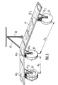
- the linear development sensor of FIG. 3 consists of three wheels 41, 42 and 43 corresponding respectively to the electrodes X1, X2 and X3, X2 comprising a metal electrode attached to the electrode Cu / CuSO4, is three electrodes being held parallel by through a frame 44, consisting of two wooden planks connected to the axes of the wheels by bars.
- d2 is equal to 30 cm and d3 is equal to 1 m.
- Double shock absorbers, 451, 452 and 453, are arranged at the level of the three wheels 41, 42 and 43, in order to absorb the small roughness of the ground.
- the sensor also comprises a handle 47, in the shape of a T, connected to the chassis, making it possible to direct said sensor. On this handle is welded a stand 48 to maintain the linear sensor in the rest position.
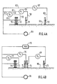
- the linear sensor of FIG. 4A consists only of three Cu / CuSO4 electrodes, 51, 52 and 53, and of a metal electrode 54 attached to the electrode 52, all of them placed on the ground 66. This sensor is connected to three voltmeters 55, 56 and 57, respectively via the electrical connections 58, 59 and 60 originating from the electrical contacts of the copper of the electrodes 51, 52 53.
- the second terminal of the voltmeters 55, 56, 57 is connected by the electrical connections 61, 62 and 63 to the buried conduit 64, disposed vertically under the electrode 51, via a valve touching the ground surface, not shown in the figure.
- the electrical connection 65 connecting the metal electrode 54 to the valve makes it possible to bring the potential of the conduit 64 to ground level, near the Cu / CuSO4 electrode 52.
- This sensor makes it possible to continuously measure the three potential differences, V1, between the conduit 64 and the electrode 52, V2, between the two electrodes 54 and 52, and V3, between the electrode 53 and the conduit 64.
- the linear sensor of FIG. 4B is made up of four Cu / CuSO4 electrodes, 71, 72, 73 and 74, and of a metal electrode 75 attached to the electrode 72, all arranged on the ground 80.
- V3 is measured by a voltmeter connected to the electrode 73 and to electrode 74 and placed at a distance equal to 600 mm from electrode 71.
- V1, V2 and V3 can be measured continuously when the sensor rolls on the ground above the buried pipe.
- the block 90 represents the measurement system constituted by the sensor 92 and at least the three voltmeters 93, 94 and 95. These three voltmeters are connected respectively to three amplifiers 96, 97 and 98 of the display system and d acquisition of data 91, themselves connected to analog-digital converters 99, 100, 101. These converters are connected to a display device 102, consisting of digital displays for reading on the site the values V1, V2, and V3, when the sensor is rolled or moved, and to a magnetic recorder 103, allowing the conservation of this data.
- the diagram in FIG. 6 illustrates the functions of the data processing system, namely the reading at 110 of the recorded data, the normalization at 111 of the values V1, V2, and V3, as a function of the values of the real potentials of the electrodes Cu / CuSO4 used, which are measured off site, and the calculation in 112 and 113 of the differences V1 - V2 and V3 - V1.
- the first diagnosis is a control diagnosis: it was made according to the procedure known to those skilled in the art, which consists in measuring: - the potential difference V between the ground and the structure, using a Cu / CuSO4 electrode, connected to a voltmeter, itself connected to the structure; - the resistivity ⁇ soil in the vicinity of the structure, using a Wenner bridge; - pH, using a pH meter, by coring the soil in the vicinity of the structure.
- V1 V2 and V3
- a linear development sensor with three Cu / CuSO4 electrodes was used as described in relation to FIGS. 3 and 4A.
- An intensity of the corrosive effect equal to 100% corresponds to corrosion causing the start of leakage of the fluid stored in the structure at the level of the anode zone. It can be seen that only one zone, zone 3, is very corroded, while zones 2 and 4 are moderately corroded and zones 1 and 5 are slightly corroded. It will therefore be possible, in the light of these results, to intervene at the level of corroded areas of the structures buried in the ground of the station.
- the corrosion diagnosis obtained according to the process of the invention makes it possible to locate the anodic zones with a precision of a few centimeters and to quantify the risks of corrosion and leakage of the product at their level.
Landscapes
- Life Sciences & Earth Sciences (AREA)
- General Health & Medical Sciences (AREA)
- Immunology (AREA)
- Environmental & Geological Engineering (AREA)
- Environmental Sciences (AREA)
- Physics & Mathematics (AREA)
- Health & Medical Sciences (AREA)
- Chemical & Material Sciences (AREA)
- Analytical Chemistry (AREA)
- Biochemistry (AREA)
- Biodiversity & Conservation Biology (AREA)
- Ecology (AREA)
- Pathology (AREA)
- General Physics & Mathematics (AREA)
- Testing Resistance To Weather, Investigating Materials By Mechanical Methods (AREA)
- Analysing Materials By The Use Of Radiation (AREA)
- Investigating Or Analyzing Materials By The Use Of Electric Means (AREA)
- Preventing Corrosion Or Incrustation Of Metals (AREA)
- Investigating And Analyzing Materials By Characteristic Methods (AREA)
- Geophysics And Detection Of Objects (AREA)
- Sampling And Sample Adjustment (AREA)
- Investigating Or Analyzing Non-Biological Materials By The Use Of Chemical Means (AREA)
Priority Applications (1)
| Application Number | Priority Date | Filing Date | Title |
|---|---|---|---|
| AT86402960T ATE91790T1 (de) | 1985-12-31 | 1986-12-30 | Verfahren und vorrichtung zur untersuchung der korrodierenden wirkung des bodens und dessen umgebung auf eine metallische eingegrabene struktur und anwendung zur lokalisierung dieser wirkung. |
Applications Claiming Priority (2)
| Application Number | Priority Date | Filing Date | Title |
|---|---|---|---|
| FR8519501 | 1985-12-31 | ||
| FR8519501A FR2592484B1 (fr) | 1985-12-31 | 1985-12-31 | Procede et dispositif d'analyse de l'effet corrosif du sol et de son environnement sur une structure metallique enterree et application a la localisation de cet effet. |
Publications (3)
| Publication Number | Publication Date |
|---|---|
| EP0229573A2 true EP0229573A2 (de) | 1987-07-22 |
| EP0229573A3 EP0229573A3 (en) | 1990-10-03 |
| EP0229573B1 EP0229573B1 (de) | 1993-07-21 |
Family
ID=9326373
Family Applications (1)
| Application Number | Title | Priority Date | Filing Date |
|---|---|---|---|
| EP86402960A Expired - Lifetime EP0229573B1 (de) | 1985-12-31 | 1986-12-30 | Verfahren und Vorrichtung zur Untersuchung der korrodierenden Wirkung des Bodens und dessen Umgebung auf eine metallische eingegrabene Struktur und Anwendung zur Lokalisierung dieser Wirkung |
Country Status (9)
| Country | Link |
|---|---|
| US (1) | US4806850A (de) |
| EP (1) | EP0229573B1 (de) |
| JP (1) | JPS62159039A (de) |
| AT (1) | ATE91790T1 (de) |
| AU (1) | AU591542B2 (de) |
| CA (1) | CA1300075C (de) |
| DE (1) | DE3688735T2 (de) |
| FR (1) | FR2592484B1 (de) |
| ZA (1) | ZA869533B (de) |
Cited By (3)
| Publication number | Priority date | Publication date | Assignee | Title |
|---|---|---|---|---|
| EP0353147A1 (de) * | 1988-07-26 | 1990-01-31 | Advanced Technologies Industry | Verfahren und Vorrichtung zur Bestimmung der Korrosionsgeschwindigkeit von einer vergrabenen oder versenkten ununterbrochenen metallischen Struktur |
| CH683719A5 (de) * | 1991-09-19 | 1994-04-29 | Proceq Ag | Gerät zur zerstörungsfreien Untersuchung von Stahlbetonbauwerken. |
| EP0693681A1 (de) * | 1994-07-22 | 1996-01-24 | CESCOR S.r.l. | Methode und Gerät zur Messung des ohmischen abfallfreien Potentials und zur Beschichtungsintegrität in Anwesenheit von Streuströmen |
Families Citing this family (22)
| Publication number | Priority date | Publication date | Assignee | Title |
|---|---|---|---|---|
| US4927503A (en) * | 1988-05-16 | 1990-05-22 | The United States Of America As Represented By The Secretary Of The Navy | Method for assessment of corrosion activity in reinforced concrete |
| US4940944A (en) * | 1989-02-16 | 1990-07-10 | Westinghouse Electric Corp. | Cathodic protection analyzer in which the fundamental and odd harmonics of a power line frequency are removed |
| FR2656426B1 (fr) * | 1989-12-27 | 1992-04-30 | Gaz De France | Procede et dispositif de determination des interactions dues a des courants continus sur des structures metalliques enterrees voisines. |
| US5144247A (en) * | 1991-02-14 | 1992-09-01 | Westinghouse Electric Corp. | Method and apparatus for reducing IR error in cathodic protection measurements |
| AT401579B (de) * | 1993-04-16 | 1996-10-25 | Tiefnig Eugen | Verfahren und vorrichtung zur ermittlung der korrosivität |
| US5854557A (en) * | 1993-04-16 | 1998-12-29 | Tiefnig; Eugen | Corrosion measurement system |
| US5596267A (en) * | 1994-12-22 | 1997-01-21 | Atlantic Richfield Company | Apparatus and method for measuring potentials through pavements for buried pipeline cathodic protection systems |
| US5795461A (en) * | 1996-03-26 | 1998-08-18 | Rising; Brandt A. | Electrode system for monitoring corrosion |
| US5897755A (en) * | 1997-01-31 | 1999-04-27 | Carsonite International Corporation | Cathodic protection test station |
| JP3058844B2 (ja) * | 1997-06-03 | 2000-07-04 | 東京瓦斯株式会社 | 鋼製プローブを用いたカソード防食状況の判定方法及びその装置 |
| US6356830B1 (en) * | 1998-08-11 | 2002-03-12 | Purdue Research Foundation | System and method for automated measurement of soil pH |
| US6220200B1 (en) | 1998-12-02 | 2001-04-24 | Carsonite International | Line marker with locking mechanism |
| US6801863B1 (en) * | 2003-03-10 | 2004-10-05 | Agilent Technologies, Inc. | Method for detecting the connectivity of electrical conductors during automated test using longitudinal balance measurements |
| US7459067B2 (en) * | 2003-04-28 | 2008-12-02 | Southwest Research Institute | Semi-permanent reference electrode |
| CN101865817B (zh) * | 2010-06-08 | 2011-12-14 | 天津大学 | 用于埋地金属腐蚀探测的传感器与探测方法 |
| US10247691B1 (en) | 2012-05-30 | 2019-04-02 | University Of South Florida | Systems and methods for contactless assessment of reinforced concrete |
| CN102998339B (zh) * | 2012-12-03 | 2014-10-22 | 太原理工大学 | 室内击实土腐蚀性评价装置及其使用方法 |
| CN104819997B (zh) * | 2015-05-19 | 2017-11-03 | 河海大学 | 用于盐冻环境混凝土性态的监测装置 |
| US10317358B1 (en) * | 2016-03-15 | 2019-06-11 | University Of South Florida | Systems and methods for contactless assessment of structures buried in soil |
| CN106501170A (zh) * | 2016-12-02 | 2017-03-15 | 天津哈德韦尔自控技术有限公司 | 智能便携式参比电极 |
| WO2019084694A1 (en) | 2017-11-06 | 2019-05-09 | Auscultech Inc. | System, electrode and method for evaluating a condition of steel reinforcements in concrete |
| CN113848373B (zh) * | 2021-10-27 | 2025-05-02 | 西安热工研究院有限公司 | 一种埋地管道附近土壤杂散电流测量装置及使用方法 |
Family Cites Families (18)
| Publication number | Priority date | Publication date | Assignee | Title |
|---|---|---|---|---|
| US2803797A (en) * | 1953-09-17 | 1957-08-20 | James R Cowles | Method and apparatus for indicating cathodic protection |
| US2862177A (en) * | 1955-02-28 | 1958-11-25 | Yale W Titterington | Apparatus for measuring the charge on buried conductors |
| US2974276A (en) * | 1957-08-16 | 1961-03-07 | Superior Oil Co | Method of and apparatus for use in measuring earth potentials |
| US3660249A (en) * | 1970-02-05 | 1972-05-02 | Magna Corp | Method and apparatus for determining both the average corrosion rate, and the pitting tendency, substantially independently of the resistance of the electrolyte |
| GB1342949A (en) * | 1971-12-07 | 1974-01-10 | Glazkov V I Kotik V G | Methods of measuring electrochemical potential difference |
| US3893026A (en) * | 1972-12-06 | 1975-07-01 | Vsevolod Ivanovich Glazkov | Method and apparatus for measuring electrochemical potential difference between a metallic structure and earth |
| US3999121A (en) * | 1975-08-11 | 1976-12-21 | Standard Oil Company (Indiana) | Well casing corrosion meter |
| US4051436A (en) * | 1976-04-14 | 1977-09-27 | Weir Jr Casper J | Apparatus for and method of measuring polarization potential of a metallic structure |
| DE2707265C2 (de) * | 1977-02-19 | 1982-10-14 | Ruhrgas Ag, 4300 Essen | Meßvorrichtung zur Ermittlung des Metall-/Boden-Potentials kathodisch geschützter Metallkörper |
| US4151458A (en) * | 1977-07-29 | 1979-04-24 | Harco Corporation | Closely spaced pipe-to-soil electrical survey method and apparatus |
| US4155814A (en) * | 1977-11-30 | 1979-05-22 | Csepel Muvek Femmuve | Method and apparatus for galvanostatic and potentiostatic electrochemical investigation of the rate of corrosion processes |
| JPS54149011A (en) * | 1978-05-12 | 1979-11-21 | Tokyo Gas Co Ltd | Buried metal pipe corrosion prevention method |
| US4322805A (en) * | 1979-03-05 | 1982-03-30 | Harco Corporation | Electrical survey method and apparatus |
| US4388594A (en) * | 1980-06-09 | 1983-06-14 | Harco Corporation | Semi-permeable electrolytic cell and method for surveying buried structures |
| NL8103088A (nl) * | 1981-06-26 | 1983-01-17 | Nederlandse Gasunie Nv | Inrichting voor het meten van de potentiaal ten opzichte van de bodem van een kathodisch beschermde metalen constructie. |
| CA1191899A (en) * | 1983-02-28 | 1985-08-13 | John P. Nicholson | Electrolyte potential measuring apparatus |
| US4611175A (en) * | 1984-03-22 | 1986-09-09 | The United States Of America As Represented By The Secretary Of The Army | Pipe corrosion monitor |
| US4584430A (en) * | 1985-04-08 | 1986-04-22 | Belknap Lewis J | Safety electrical receptacle cover plate |
-
1985
- 1985-12-31 FR FR8519501A patent/FR2592484B1/fr not_active Expired
-
1986
- 1986-12-18 ZA ZA869533A patent/ZA869533B/xx unknown
- 1986-12-30 AT AT86402960T patent/ATE91790T1/de active
- 1986-12-30 DE DE86402960T patent/DE3688735T2/de not_active Expired - Fee Related
- 1986-12-30 CA CA000526462A patent/CA1300075C/fr not_active Expired - Lifetime
- 1986-12-30 EP EP86402960A patent/EP0229573B1/de not_active Expired - Lifetime
- 1986-12-31 US US06/948,026 patent/US4806850A/en not_active Expired - Fee Related
- 1986-12-31 AU AU67080/86A patent/AU591542B2/en not_active Ceased
-
1987
- 1987-01-05 JP JP62000335A patent/JPS62159039A/ja active Pending
Cited By (4)
| Publication number | Priority date | Publication date | Assignee | Title |
|---|---|---|---|---|
| EP0353147A1 (de) * | 1988-07-26 | 1990-01-31 | Advanced Technologies Industry | Verfahren und Vorrichtung zur Bestimmung der Korrosionsgeschwindigkeit von einer vergrabenen oder versenkten ununterbrochenen metallischen Struktur |
| FR2634888A1 (fr) * | 1988-07-26 | 1990-02-02 | Advanced Technologies Internal | Procede et dispositif de determination de la vitesse de corrosion d'une structure metallique continue enterree ou immergee |
| CH683719A5 (de) * | 1991-09-19 | 1994-04-29 | Proceq Ag | Gerät zur zerstörungsfreien Untersuchung von Stahlbetonbauwerken. |
| EP0693681A1 (de) * | 1994-07-22 | 1996-01-24 | CESCOR S.r.l. | Methode und Gerät zur Messung des ohmischen abfallfreien Potentials und zur Beschichtungsintegrität in Anwesenheit von Streuströmen |
Also Published As
| Publication number | Publication date |
|---|---|
| JPS62159039A (ja) | 1987-07-15 |
| FR2592484B1 (fr) | 1988-04-01 |
| CA1300075C (fr) | 1992-05-05 |
| DE3688735T2 (de) | 1994-01-20 |
| AU6708086A (en) | 1987-07-02 |
| DE3688735D1 (de) | 1993-08-26 |
| EP0229573B1 (de) | 1993-07-21 |
| ATE91790T1 (de) | 1993-08-15 |
| US4806850A (en) | 1989-02-21 |
| ZA869533B (en) | 1987-08-26 |
| FR2592484A1 (fr) | 1987-07-03 |
| EP0229573A3 (en) | 1990-10-03 |
| AU591542B2 (en) | 1989-12-07 |
Similar Documents
| Publication | Publication Date | Title |
|---|---|---|
| EP0229573B1 (de) | Verfahren und Vorrichtung zur Untersuchung der korrodierenden Wirkung des Bodens und dessen Umgebung auf eine metallische eingegrabene Struktur und Anwendung zur Lokalisierung dieser Wirkung | |
| Ahuja et al. | Estimating soil water characteristics from simpler properties or limited data | |
| Vichabian et al. | Self potentials in cave detection | |
| EP1152235A1 (de) | Vorrichtung zur fortlaufend in Zeit und Raum Feststellung des Korrosionszustandes von vergrabenen metallischen Strukturen | |
| Bernalte et al. | The effect of slicer infill pattern on the electrochemical performance of additively manufactured electrodes | |
| Martínez-Pagán et al. | Self-potential monitoring of a salt plume | |
| EP0131517A2 (de) | Armmechanismus zur Unterstützung des Schuhes eines Bohrlochmessgeräts | |
| JP2010266342A (ja) | 金属の腐食診断方法 | |
| EP2959318B1 (de) | Verfahren und vorrichtung zur bestimmung der radiologischen aktivität auf einem meeresboden | |
| Payne et al. | Identifying nanoscale pinhole defects in nitroaryl layers with scanning electrochemical cell microscopy | |
| Dimech et al. | 3D time-lapse geoelectrical monitoring of moisture content in an experimental waste rock pile: Validation using hydrogeological data | |
| JP7007590B2 (ja) | 電極、腐食解析装置および腐食解析方法 | |
| JP2002062362A (ja) | 盛土土工部の検査方法 | |
| CN211668986U (zh) | 一种公路压实度试验检测设备 | |
| FR2610114A1 (fr) | Procede et appareillage de detection continue des variations du type ou de l'etat des roches avoisinant un tunnelier par une methode electrique | |
| CN112816162A (zh) | 一种垃圾填埋系统及垃圾渗漏监测方法 | |
| Niu et al. | Evaluation of the capacitively coupled resistivity (line antenna) method for the characterization of vadose zone dynamics | |
| Mudd | Control of Pipe-Line Corrosion—A Manual | |
| Moroizumi et al. | Estimating the nonaqueous‐phase liquid content in saturated sandy soil using amplitude domain reflectometry | |
| Kusuyama et al. | Effectiveness of resistivity monitoring for unsaturated water flow in landfill sites | |
| JP2001074850A (ja) | 無分極電極を用いる電気探査方法 | |
| CN213985593U (zh) | 一种垃圾填埋系统 | |
| JPS6234296Y2 (de) | ||
| Waters | Soil resistivity measurements for corrosion control | |
| YJ Tan et al. | A new approach to probing localized corrosion of pipelines |
Legal Events
| Date | Code | Title | Description |
|---|---|---|---|
| PUAI | Public reference made under article 153(3) epc to a published international application that has entered the european phase |
Free format text: ORIGINAL CODE: 0009012 |
|
| AK | Designated contracting states |
Kind code of ref document: A2 Designated state(s): AT BE DE GB IT NL |
|
| PUAL | Search report despatched |
Free format text: ORIGINAL CODE: 0009013 |
|
| AK | Designated contracting states |
Kind code of ref document: A3 Designated state(s): AT BE DE GB IT NL |
|
| 17P | Request for examination filed |
Effective date: 19901126 |
|
| 17Q | First examination report despatched |
Effective date: 19920504 |
|
| RAP1 | Party data changed (applicant data changed or rights of an application transferred) |
Owner name: TOTAL RAFFINAGE DISTRIBUTION S.A. |
|
| GRAA | (expected) grant |
Free format text: ORIGINAL CODE: 0009210 |
|
| ITF | It: translation for a ep patent filed | ||
| AK | Designated contracting states |
Kind code of ref document: B1 Designated state(s): AT BE DE GB IT NL |
|
| REF | Corresponds to: |
Ref document number: 91790 Country of ref document: AT Date of ref document: 19930815 Kind code of ref document: T |
|
| REF | Corresponds to: |
Ref document number: 3688735 Country of ref document: DE Date of ref document: 19930826 |
|
| GBT | Gb: translation of ep patent filed (gb section 77(6)(a)/1977) |
Effective date: 19931008 |
|
| PLBE | No opposition filed within time limit |
Free format text: ORIGINAL CODE: 0009261 |
|
| STAA | Information on the status of an ep patent application or granted ep patent |
Free format text: STATUS: NO OPPOSITION FILED WITHIN TIME LIMIT |
|
| 26N | No opposition filed | ||
| PGFP | Annual fee paid to national office [announced via postgrant information from national office to epo] |
Ref country code: GB Payment date: 19941125 Year of fee payment: 9 |
|
| PGFP | Annual fee paid to national office [announced via postgrant information from national office to epo] |
Ref country code: BE Payment date: 19941214 Year of fee payment: 9 |
|
| PGFP | Annual fee paid to national office [announced via postgrant information from national office to epo] |
Ref country code: AT Payment date: 19941220 Year of fee payment: 9 |
|
| PGFP | Annual fee paid to national office [announced via postgrant information from national office to epo] |
Ref country code: DE Payment date: 19941229 Year of fee payment: 9 |
|
| PGFP | Annual fee paid to national office [announced via postgrant information from national office to epo] |
Ref country code: NL Payment date: 19941231 Year of fee payment: 9 |
|
| PG25 | Lapsed in a contracting state [announced via postgrant information from national office to epo] |
Ref country code: GB Effective date: 19951230 Ref country code: AT Effective date: 19951230 |
|
| PG25 | Lapsed in a contracting state [announced via postgrant information from national office to epo] |
Ref country code: BE Effective date: 19951231 |
|
| BERE | Be: lapsed |
Owner name: S.A. TOTAL RAFFINAGE DISTRIBUTION Effective date: 19951231 |
|
| PG25 | Lapsed in a contracting state [announced via postgrant information from national office to epo] |
Ref country code: NL Effective date: 19960701 |
|
| GBPC | Gb: european patent ceased through non-payment of renewal fee |
Effective date: 19951230 |
|
| NLV4 | Nl: lapsed or anulled due to non-payment of the annual fee |
Effective date: 19960701 |
|
| PG25 | Lapsed in a contracting state [announced via postgrant information from national office to epo] |
Ref country code: DE Effective date: 19960903 |
|
| PG25 | Lapsed in a contracting state [announced via postgrant information from national office to epo] |
Ref country code: IT Free format text: LAPSE BECAUSE OF NON-PAYMENT OF DUE FEES;WARNING: LAPSES OF ITALIAN PATENTS WITH EFFECTIVE DATE BEFORE 2007 MAY HAVE OCCURRED AT ANY TIME BEFORE 2007. THE CORRECT EFFECTIVE DATE MAY BE DIFFERENT FROM THE ONE RECORDED. Effective date: 20051230 |