EP0229610B1 - Dispositif pour granuler des cordes en matière thermoplastique - Google Patents
Dispositif pour granuler des cordes en matière thermoplastique Download PDFInfo
- Publication number
- EP0229610B1 EP0229610B1 EP87100030A EP87100030A EP0229610B1 EP 0229610 B1 EP0229610 B1 EP 0229610B1 EP 87100030 A EP87100030 A EP 87100030A EP 87100030 A EP87100030 A EP 87100030A EP 0229610 B1 EP0229610 B1 EP 0229610B1
- Authority
- EP
- European Patent Office
- Prior art keywords
- cooling water
- cutting roller
- strands
- cooling
- support surface
- Prior art date
- Legal status (The legal status is an assumption and is not a legal conclusion. Google has not performed a legal analysis and makes no representation as to the accuracy of the status listed.)
- Expired - Lifetime
Links
Images
Classifications
-
- B—PERFORMING OPERATIONS; TRANSPORTING
- B29—WORKING OF PLASTICS; WORKING OF SUBSTANCES IN A PLASTIC STATE IN GENERAL
- B29B—PREPARATION OR PRETREATMENT OF THE MATERIAL TO BE SHAPED; MAKING GRANULES OR PREFORMS; RECOVERY OF PLASTICS OR OTHER CONSTITUENTS OF WASTE MATERIAL CONTAINING PLASTICS
- B29B7/00—Mixing; Kneading
-
- B—PERFORMING OPERATIONS; TRANSPORTING
- B29—WORKING OF PLASTICS; WORKING OF SUBSTANCES IN A PLASTIC STATE IN GENERAL
- B29B—PREPARATION OR PRETREATMENT OF THE MATERIAL TO BE SHAPED; MAKING GRANULES OR PREFORMS; RECOVERY OF PLASTICS OR OTHER CONSTITUENTS OF WASTE MATERIAL CONTAINING PLASTICS
- B29B9/00—Making granules
- B29B9/02—Making granules by dividing preformed material
- B29B9/06—Making granules by dividing preformed material in the form of filamentary material, e.g. combined with extrusion
- B29B9/065—Making granules by dividing preformed material in the form of filamentary material, e.g. combined with extrusion under-water, e.g. underwater pelletizers
-
- B—PERFORMING OPERATIONS; TRANSPORTING
- B29—WORKING OF PLASTICS; WORKING OF SUBSTANCES IN A PLASTIC STATE IN GENERAL
- B29B—PREPARATION OR PRETREATMENT OF THE MATERIAL TO BE SHAPED; MAKING GRANULES OR PREFORMS; RECOVERY OF PLASTICS OR OTHER CONSTITUENTS OF WASTE MATERIAL CONTAINING PLASTICS
- B29B9/00—Making granules
- B29B9/02—Making granules by dividing preformed material
- B29B9/06—Making granules by dividing preformed material in the form of filamentary material, e.g. combined with extrusion
-
- B—PERFORMING OPERATIONS; TRANSPORTING
- B29—WORKING OF PLASTICS; WORKING OF SUBSTANCES IN A PLASTIC STATE IN GENERAL
- B29C—SHAPING OR JOINING OF PLASTICS; SHAPING OF MATERIAL IN A PLASTIC STATE, NOT OTHERWISE PROVIDED FOR; AFTER-TREATMENT OF THE SHAPED PRODUCTS, e.g. REPAIRING
- B29C2793/00—Shaping techniques involving a cutting or machining operation
- B29C2793/009—Shaping techniques involving a cutting or machining operation after shaping
Definitions
- the invention relates to a device for granulating strands of thermoplastic materials which emerge from a plurality of nozzles arranged in a row next to one another in a molten state, with a cutting roller acting on a counter knife and a feed device which is arranged in front of the cutting roller and is supplied with cooling water.
- the feed device consists of a drainage channel, the upper end of which is provided with a cooling water inlet and the lower end of which ends before the feed nip of a pair of feed rollers, behind which the cutting roller with counter knife is arranged.
- the gutter can be sprayed with cooling water.
- thermoplastic materials can be granulated into cylinder granulate, the viscosity of which can take on extremely extreme values immediately behind the outlet from the nozzles. This universality is made possible by the drainage channel, with which the desired cooling can be achieved in a wide range.
- the mode of operation of this device is referred to as a cold granulation process, in which the process steps extrusion - cooling - cutting are connected in series in this order (see “Granulation of thermoplastics, page 139, VDI-Verlag GmbH).
- the so-called hot granulation process is also known, in which the individual process steps follow one another as follows: extrusion - cutting - cooling.
- a device operating according to this method is known from DE-PS 2 809 680.
- the typical feature of this procedure and, accordingly, of the device is that a knife rotor with its knives sweeps over the nozzle surface in contact with one another, the nozzles thus forming the counter knife for the knife rotor.
- the knife rotor is designed as a milling cutter with helically running cutting edges. Since this method cuts the respective knife in still molten plastic, this method can only be used with a few plastics, e.g. B. polystyrene. In this method, the expense of a special cooling section between the extrusion and the cutting is avoided, but the effect of the nozzles as a counter knife requires their special design, in particular of hard material.
- the object of the invention is to largely eliminate the effort previously required for special cooling sections, without, however, having to accept the limitation in terms of the scope of application as it adheres to the hot granulating devices.
- the problem is solved in that the feed device consists of the support surface of the counter knife which is approximately radial to the cutting roller and which essentially completely fills the space between the nozzle surface and the cutting roller.
- a cooling section is sufficient for a wide range of thermoplastics to create cylindrical granules, which only consists of the supporting surface of the counter knife, which is necessary anyway for the cutting roller, and which is thus used twice, namely on the one hand to support the strands as they pass through this particularly short cooling section and on the other hand for cutting as a counter knife interacting with the cutting roller.
- the use of the support surface in this sense has the further advantage that the area between the nozzle surface and the cutting roller remains easily accessible, which is not the case with cooling sections consisting of pipes.
- the invention thus creates a class of pelletizing devices which basically work according to the cold pelletizing process, but which manage with minimal effort.
- contact between the cutting roller and counter knife is not required, it is also not used in the cold granulation process, since the cutting roller and counter knife meet plastic strands that are already solidified on the surface and can be cut even with a small distance between the cutting roller and counter knife. These distances are up to about 0.03 mm.
- the support surface of the counter knife is expediently arranged opposite spray nozzles.
- the cooling water jets directed by these spray nozzles onto the support surface envelop the strands guided over the support surface in a spray mist, the cooling water also getting behind the strands in a sufficient manner and thus on the one hand sticking the strands to the counter knife and on the other hand adequate cooling of the surface of the strands causes.
- the counter knife With cooling water by directing a stream of cooling water onto the cutting roller, which throws off the cooling water and sprays it onto the supporting surface of the counter knife.
- This measure can be used alone or together with the spray nozzles. In any case, this results in the cooling water mist acting on the counter knife, which is still desirable insofar as it only has a cooling effect but does not lead to a deformation of the strands.
- the strands in the area of the counter knife are expediently given special guidance, specifically by providing the counter knife with guide grooves for the strands. This prevents the strands from migrating sideways and possibly sticking together. Otherwise, the guide grooves result in cooling water baths for the strands, which benefits the intensity of the cooling.
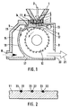
- FIG. 1 shows the feed hopper 1 for the feed of liquid plastic, which runs through the feed hopper 1 in the direction of the arrow 2 shown.
- the feed hopper 1 has at its lower end the nozzle plate 3, which contains a number of nozzles arranged side by side, of which only the nozzle 4 is visible here.
- the nozzles in the nozzle plate 3 are, as shown in FIG. 1, one behind the other in the viewing direction.
- the nozzle plate 3 is provided on its underside with the cross-created insulation 5, which ensures that only little heat can be removed from the nozzle plate by the components arranged below it.
- the heating elements 6 and 7 are arranged in it.
- the insulation 5 has an opening 8 which is widened relative to the nozzle 4, so that molten plastic passing through the nozzle 4 cannot stick to the insulation 5.
- the feed hopper 1 with the nozzle plate 3 and the insulation 5 sits on the housing 9 that surrounds the components required for the granulation. These consist of the cutting roller 10 and the counter knife 11 that is included in the wall of the housing 9 here.
- the strands emerging from the nozzles 4 pass through the opening 8 in the insulation 5 and run over the support surface 12 of the counter knife 11 until they reach the cutting roller 10, from which they are then cut into granules in a known manner.
- the spray nozzle is arranged opposite the support surface 12 of the counter knife 11, which sprays cooling water onto the support surface, whereby the plastic strands guided over the support surface 12 are cooled.
- a cooling water mist is generated in front of the support surface 12, which surrounds the strands on all sides, and cools them without leading to a deformation of the strands.
- the cooling path thus formed by the support surface of the counter knife, which completely fills the space between the surface of the insulation 5 and the cutting roller 10, is approximately 10 mm long. This length is sufficient to solidify the plastic strands on their surface to such an extent that they can be cut into granules by the cutting roller 10 without them sticking to one another, which is also prevented by a cooling water inlet which emerges through the opening 14 and onto the Cutting roller is directed. This will be discussed in more detail below.
- the length of the cooling section formed by the support surface 12 can be approximately 5-30 mm.
- the water tank 15 is installed, to which the water is fed via the inlet opening 16.
- the water tank is essentially formed by the bottom 17 of the housing 9, the wall of the housing 9 adjoining the inlet opening 16 and the inner wall 18.
- the water rises in the water tank 15 and reaches the slot 19 and the opening 14, from which the latter is fed to the cutting roller 10.
- the cooling water emerging from the slot 19 flows down on the cutting roller 16 facing the side of the inner wall 18, is then passed over the bottom 17 and emerges together with the granules from the outlet 20, in the direction of the arrow 21 shown
- the inner wall 18 and the bottom 7 of the cooling water wash the granules produced out of the housing 9 in this way.
- the cooling water supplied to the cutting roller 10 via the opening 14 is whirled along by the cutting roller 10 and thrown away again, a substantial part of this water spraying onto the supporting surface 12 of the counter knife 11, which is indicated by the lines drawn in front of the supporting surface 12.
- the support surface 12 is also sprayed with cooling water by means of the cutting roller 10.
- either the spray nozzle 13 or spraying by cooling water thrown off the knife roller 10 can be used, but it is of course also possible to provide both spraying methods simultaneously.
- Figure 2 shows a section through the counter knife 11, which is provided here on its side facing the strands 22 with the guide grooves 23, of which the strands 22 are guided so that they do not migrate laterally in the area between the nozzle 4 and the cutting knife 10 can.
Landscapes
- Engineering & Computer Science (AREA)
- Mechanical Engineering (AREA)
- Processing And Handling Of Plastics And Other Materials For Molding In General (AREA)
Claims (4)
- Dispositif pour granuler des boudins de matière thermoplastique qui sortent en fusion de plusieurs filières disposées en une rangée les unes à côté des autres, avec un cylindre de coupe agissant sur une contre-lame et avec un dispositif d'alimentation disposé avant le cylindre de coupe et approvisionné en eau de refroidissement,
caractérisé en ce que le dispositif d'alimentation est constitué par la face d'appui (12) de la contre-lame (11), face qui est disposée approximativement radialement au cylindre de coupe (10), qui remplit sensiblement totalement l'espace intermédiaire entre la surface des filières et le cylindre de coupe (10), et sur laquelle est pulvérisée l'eau de refroidissement. - Dispositif selon la revendication 1, caractérisé en ce que des buses de pulvérisation (13) sont disposées en vis-à-vis de la face d'appui (12) de la contre-lame (11).
- Dispositif selon la revendication 1 ou 2, caractérisé en ce qu'un flux d'eau de refroidissement est dirigé sur le cylindre de coupe (10), qui entraîne l'eau de refroidissement et la pulvérise sur la face d'appui (12) de la contre-lame (11).
- Dispositif selon l'une des revendications 1 à 3, caractérisé en ce que la contre-lame (11) est pourvue de rainures de guidage (23) pour les boudins (22).
Priority Applications (1)
| Application Number | Priority Date | Filing Date | Title |
|---|---|---|---|
| AT87100030T ATE74551T1 (de) | 1986-01-10 | 1987-01-02 | Vorrichtung zum granulieren von straengen aus thermoplastischen kunststoffen. |
Applications Claiming Priority (2)
| Application Number | Priority Date | Filing Date | Title |
|---|---|---|---|
| DE3600567A DE3600567C1 (de) | 1986-01-10 | 1986-01-10 | Vorrichtung zum Granulieren von Straengen aus thermoplastischen Kunststoffen |
| DE3600567 | 1986-01-10 |
Publications (3)
| Publication Number | Publication Date |
|---|---|
| EP0229610A2 EP0229610A2 (fr) | 1987-07-22 |
| EP0229610A3 EP0229610A3 (en) | 1989-09-20 |
| EP0229610B1 true EP0229610B1 (fr) | 1992-04-08 |
Family
ID=6291647
Family Applications (1)
| Application Number | Title | Priority Date | Filing Date |
|---|---|---|---|
| EP87100030A Expired - Lifetime EP0229610B1 (fr) | 1986-01-10 | 1987-01-02 | Dispositif pour granuler des cordes en matière thermoplastique |
Country Status (7)
| Country | Link |
|---|---|
| US (1) | US4838775A (fr) |
| EP (1) | EP0229610B1 (fr) |
| JP (1) | JPH0741615B2 (fr) |
| KR (1) | KR910000286B1 (fr) |
| AT (1) | ATE74551T1 (fr) |
| DE (2) | DE3600567C1 (fr) |
| ES (1) | ES2030002T3 (fr) |
Cited By (1)
| Publication number | Priority date | Publication date | Assignee | Title |
|---|---|---|---|---|
| US9439862B2 (en) | 2000-05-10 | 2016-09-13 | Novartis Ag | Phospholipid-based powders for drug delivery |
Families Citing this family (12)
| Publication number | Priority date | Publication date | Assignee | Title |
|---|---|---|---|---|
| JPH0613175B2 (ja) * | 1989-07-31 | 1994-02-23 | 株式会社クラレ | ペレツトの製造法 |
| US5265507A (en) * | 1989-07-31 | 1993-11-30 | Kuraray Co., Ltd. | Process for producing pellets |
| US5458836B1 (en) * | 1994-03-11 | 1998-08-04 | Du Pont | Polymer extrusion die and use thereof |
| US5545025A (en) * | 1994-10-03 | 1996-08-13 | Katsu Manufacturing Co., Ltd. | Cooled pellet making machine |
| DE10100190C1 (de) * | 2001-01-04 | 2002-06-20 | Scheer & Cie C F | Kunststoffstranggranulator und Verfahren zum Beeinflussen der Spaltbreite zwischen einer Messerwalze und einem Gegenmesser in einem Kunststoffstranggranulator |
| FR2856950B1 (fr) * | 2003-07-04 | 2007-03-02 | Rhodia Polyamide Intermediates | Procede de preparation de perle a base de polymere expanse |
| US7124972B2 (en) * | 2003-09-04 | 2006-10-24 | Scheer Bay Limited Partnership | System and apparatus for manufacturing thermoplastic micropellets |
| DE102007027418A1 (de) * | 2007-06-14 | 2008-12-18 | Rieter Automatik Gmbh | Stranggranulator zum Granulieren von Kunststoffsträngen |
| DE102007044201A1 (de) * | 2007-09-17 | 2009-03-19 | Rieter Automatik Gmbh | Vorrichtung zum Granulieren von Kunststoffsträngen |
| CN107520890A (zh) * | 2017-09-07 | 2017-12-29 | 何冰 | 一种环保型电缆料切粒机 |
| DE102019127759B4 (de) * | 2019-10-15 | 2021-12-30 | Maag Automatik Gmbh | Kunststoffstranggranulator |
| CN115339779B (zh) * | 2022-08-12 | 2024-04-30 | 凯迈(洛阳)机电有限公司 | 一种可快速拆解的切粒机启动头水箱 |
Family Cites Families (20)
| Publication number | Priority date | Publication date | Assignee | Title |
|---|---|---|---|---|
| US2324397A (en) * | 1941-06-04 | 1943-07-13 | Du Pont | Method for production of continuous structures |
| US3070835A (en) * | 1960-01-12 | 1963-01-01 | Standard Oil Co | Pump quenching of polymer solvent mixtures |
| US3076999A (en) * | 1960-04-25 | 1963-02-12 | Du Pont | Extrusion and bead cutting machine |
| US3753637A (en) * | 1972-02-14 | 1973-08-21 | Midland Ross Corp | Cooled-cutter hot-die pelletizer |
| US3792950A (en) * | 1972-09-08 | 1974-02-19 | Cumberland Eng Co | Pelletizing apparatus |
| DE2503455B2 (de) * | 1975-01-28 | 1977-06-16 | Ausscheidung in: 25 59 541 Automatik Apparate-Maschinenbau H. Hench GmbH, 8754 Großostheim | Vorrichtung zum abkuehlen und granulieren von straengen aus thermoplastischen kunststoffen |
| US4025252A (en) * | 1975-01-28 | 1977-05-24 | Automatik Apparate-Maschinebau H. Hench Gmbh | Granulating apparatus, especially for strands of thermoplastic materials |
| DE2600078C3 (de) * | 1976-01-02 | 1978-10-05 | Automatik Apparate-Maschinenbau H. Hench Gmbh, 8754 Grossostheim | Vorrichtung zum Granulieren von Strängen aus thermoplastischen Kunststoffen |
| FR2285973A1 (fr) * | 1975-09-29 | 1976-04-23 | Shell Int Research | Appareil pour granuler une matiere thermoplastique synthetique |
| US3988085A (en) * | 1975-11-24 | 1976-10-26 | Krchma Ludwig C | Apparatus for forming uniform shaped particles of thermoplastic material |
| SU680627A4 (ru) * | 1976-12-09 | 1979-08-15 | Аутоматик Аппарате-Машиненбау Ханс Хенх Гмбх, (Фирма) | Устройство дл гранулировани прутков из термопластичных материалов |
| JPS6029940B2 (ja) * | 1977-08-29 | 1985-07-13 | 株式会社リコー | 積層型電子写真感光体及びその製造法 |
| DE2809680C2 (de) * | 1978-03-07 | 1983-03-03 | Leistritz Maschinenfabrik Paul Leistritz GmbH, 8500 Nürnberg | Heißabschlaggranuliereinrichtung für Strangpressen |
| DE2854024C2 (de) * | 1978-03-07 | 1987-11-12 | Leistritz Maschinenfabrik Paul Leistritz GmbH, 8500 Nürnberg | Heißabschlaggranuliereinrichtung für Strangpressen |
| US4300877A (en) * | 1979-01-10 | 1981-11-17 | Sterling Extruder Corp. | Underwater pelletizer |
| US4219291A (en) * | 1979-03-14 | 1980-08-26 | Hoeh James A | Segmented helical rotary cutter and method of making same |
| US4340342A (en) * | 1981-01-16 | 1982-07-20 | The B. F. Goodrich Company | Apparatus for processing elastomeric materials |
| DE3145613C2 (de) * | 1981-11-17 | 1984-06-07 | Automatik Apparate-Maschinenbau H. Hench Gmbh, 8754 Grossostheim | Vorrichtung zum Zuleiten von aus Düsen schmelzflüssig austretenden Kunststoffsträngen zu einer Granuliervorrichtung |
| DE3336032C2 (de) * | 1983-10-04 | 1985-12-12 | AUTOMATIK Apparate-Maschinenbau GmbH, 8754 Großostheim | Vorrichtung zum Abkühlen, Trocknen und Granulieren von Strängen aus thermoplastischen Kunststoffen |
| CA1253833A (fr) * | 1984-11-06 | 1989-05-09 | Akira Yada | Preparation de particules de gel polymere solubles a l'eau |
-
1986
- 1986-01-10 DE DE3600567A patent/DE3600567C1/de not_active Expired
-
1987
- 1987-01-02 DE DE8787100030T patent/DE3778038D1/de not_active Expired - Fee Related
- 1987-01-02 EP EP87100030A patent/EP0229610B1/fr not_active Expired - Lifetime
- 1987-01-02 AT AT87100030T patent/ATE74551T1/de not_active IP Right Cessation
- 1987-01-02 ES ES198787100030T patent/ES2030002T3/es not_active Expired - Lifetime
- 1987-01-08 US US07/001,396 patent/US4838775A/en not_active Expired - Fee Related
- 1987-01-09 JP JP62003910A patent/JPH0741615B2/ja not_active Expired - Lifetime
- 1987-01-10 KR KR1019870000150A patent/KR910000286B1/ko not_active Expired
Cited By (1)
| Publication number | Priority date | Publication date | Assignee | Title |
|---|---|---|---|---|
| US9439862B2 (en) | 2000-05-10 | 2016-09-13 | Novartis Ag | Phospholipid-based powders for drug delivery |
Also Published As
| Publication number | Publication date |
|---|---|
| DE3778038D1 (de) | 1992-05-14 |
| JPS62218111A (ja) | 1987-09-25 |
| ES2030002T3 (es) | 1992-10-16 |
| EP0229610A2 (fr) | 1987-07-22 |
| JPH0741615B2 (ja) | 1995-05-10 |
| KR870006969A (ko) | 1987-08-13 |
| ATE74551T1 (de) | 1992-04-15 |
| EP0229610A3 (en) | 1989-09-20 |
| KR910000286B1 (ko) | 1991-01-24 |
| DE3600567C1 (de) | 1987-05-07 |
| US4838775A (en) | 1989-06-13 |
Similar Documents
| Publication | Publication Date | Title |
|---|---|---|
| EP0452376B1 (fr) | Dispositif de refroidissement, de sechage et de granulation de cordons | |
| EP0651694B1 (fr) | Procede permettant le sechage et la cristallisation simultanes d'une matiere thermoplastique cristallisable | |
| DE4026337C2 (fr) | ||
| EP0539744B1 (fr) | Méthode et appareil pour refroidir et granuler un matériau en fusion en sortie de filière | |
| DE2236823A1 (de) | Lochplatte fuer eine granuliervorrichtung fuer stranggepresste kunststoffe | |
| DE4419786C1 (de) | Heißabschlag-Granuliervorrichtung | |
| EP0229610A2 (fr) | Dispositif pour granuler des cordes en matière thermoplastique | |
| DE2814113A1 (de) | Vorrichtung zum granulieren von kunststoffstraengen | |
| DE1940703U (de) | Granuliervorrichtung. | |
| DE2121914A1 (de) | Vorrichtung und Verfahren zum Strangpressen von thermoplastischen Kunststoffen | |
| DE1454757A1 (de) | Granuliervorrichtung,insbesondere fuer thermoplastische Kunststoffe | |
| DE1292792B (de) | Kuehlvorrichtung fuer eine Maschine mit beweglichen Giessbaendern zum Stranggiessen von Metallen | |
| DE3145613A1 (de) | "vorrichtung zum zuleiten von schmelzfluessigen kunststoffstraengen zu einer schraegen ablaufrinne" | |
| DE1454888B2 (de) | Vorrichtung zum granulieren von thermoplastischen kunst stoffen | |
| DE3831562A1 (de) | Verfahren und vorrichtung zum spritzen eines luftstroms in metallformen in spritzgussmaschinen | |
| DE2218210C2 (de) | Vorrichtung zum Abkühlen und Granulieren von Strängen aus thermoplastischen Kunststoffen | |
| DE3726606A1 (de) | Vorrichtung zum zufuehren und abkuehlen von straengen aus thermoplastischen kunststoffen | |
| DE3009185C2 (de) | Vorrichtung zum Schmelzen und Mischen thermoplastischer Stoffe | |
| DE4439774B4 (de) | Vorrichtung zum Granulieren von Kunststoff-Strängen | |
| DE4414753C2 (de) | Verfahren und Vorrichtung zum Abkühlen und Granulieren von Kunststoff-Strängen | |
| DE8600491U1 (de) | Vorrichtung zum Granulieren von Strängen aus thermoplastischen Kunststoffen | |
| DE69712140T2 (de) | Extrusionskopf für eine Kautschukmischung mit einer Vorrichtung zur Wiederverwertung der Entgratungsabfälle, und Wiederverwertungsvorrichtung zur Montage auf einen Extrusionskopf | |
| EP2178685B1 (fr) | Granulateur en continu pour granulation de joncs en matière plastique | |
| DE2212345C3 (de) | Vorrichtung zum Granulieren thermoplastischer Kunststoffstränge | |
| AT394155B (de) | Vorrichtung zum granulieren von kunststoffmaterial |
Legal Events
| Date | Code | Title | Description |
|---|---|---|---|
| PUAI | Public reference made under article 153(3) epc to a published international application that has entered the european phase |
Free format text: ORIGINAL CODE: 0009012 |
|
| AK | Designated contracting states |
Kind code of ref document: A2 Designated state(s): AT BE CH DE ES FR GB IT LI NL |
|
| PUAL | Search report despatched |
Free format text: ORIGINAL CODE: 0009013 |
|
| AK | Designated contracting states |
Kind code of ref document: A3 Designated state(s): AT BE CH DE ES FR GB IT LI NL |
|
| 17P | Request for examination filed |
Effective date: 19900320 |
|
| 17Q | First examination report despatched |
Effective date: 19910426 |
|
| RAP1 | Party data changed (applicant data changed or rights of an application transferred) |
Owner name: AUTOMATIK APPARATE-MASCHINENBAU GMBH |
|
| GRAA | (expected) grant |
Free format text: ORIGINAL CODE: 0009210 |
|
| AK | Designated contracting states |
Kind code of ref document: B1 Designated state(s): AT BE CH DE ES FR GB IT LI NL |
|
| REF | Corresponds to: |
Ref document number: 74551 Country of ref document: AT Date of ref document: 19920415 Kind code of ref document: T |
|
| ITF | It: translation for a ep patent filed | ||
| REF | Corresponds to: |
Ref document number: 3778038 Country of ref document: DE Date of ref document: 19920514 |
|
| GBT | Gb: translation of ep patent filed (gb section 77(6)(a)/1977) | ||
| ET | Fr: translation filed | ||
| REG | Reference to a national code |
Ref country code: ES Ref legal event code: FG2A Ref document number: 2030002 Country of ref document: ES Kind code of ref document: T3 |
|
| PLBE | No opposition filed within time limit |
Free format text: ORIGINAL CODE: 0009261 |
|
| STAA | Information on the status of an ep patent application or granted ep patent |
Free format text: STATUS: NO OPPOSITION FILED WITHIN TIME LIMIT |
|
| 26N | No opposition filed | ||
| PGFP | Annual fee paid to national office [announced via postgrant information from national office to epo] |
Ref country code: AT Payment date: 19950120 Year of fee payment: 9 |
|
| PG25 | Lapsed in a contracting state [announced via postgrant information from national office to epo] |
Ref country code: AT Effective date: 19960102 |
|
| PGFP | Annual fee paid to national office [announced via postgrant information from national office to epo] |
Ref country code: GB Payment date: 19971217 Year of fee payment: 12 Ref country code: FR Payment date: 19971217 Year of fee payment: 12 |
|
| PGFP | Annual fee paid to national office [announced via postgrant information from national office to epo] |
Ref country code: BE Payment date: 19980122 Year of fee payment: 12 |
|
| PGFP | Annual fee paid to national office [announced via postgrant information from national office to epo] |
Ref country code: CH Payment date: 19980123 Year of fee payment: 12 |
|
| PGFP | Annual fee paid to national office [announced via postgrant information from national office to epo] |
Ref country code: ES Payment date: 19980129 Year of fee payment: 12 |
|
| PGFP | Annual fee paid to national office [announced via postgrant information from national office to epo] |
Ref country code: NL Payment date: 19980130 Year of fee payment: 12 |
|
| PGFP | Annual fee paid to national office [announced via postgrant information from national office to epo] |
Ref country code: DE Payment date: 19980225 Year of fee payment: 12 |
|
| PG25 | Lapsed in a contracting state [announced via postgrant information from national office to epo] |
Ref country code: GB Free format text: LAPSE BECAUSE OF NON-PAYMENT OF DUE FEES Effective date: 19990102 |
|
| PG25 | Lapsed in a contracting state [announced via postgrant information from national office to epo] |
Ref country code: ES Free format text: LAPSE BECAUSE OF NON-PAYMENT OF DUE FEES Effective date: 19990104 |
|
| PG25 | Lapsed in a contracting state [announced via postgrant information from national office to epo] |
Ref country code: LI Free format text: LAPSE BECAUSE OF NON-PAYMENT OF DUE FEES Effective date: 19990131 Ref country code: CH Free format text: LAPSE BECAUSE OF NON-PAYMENT OF DUE FEES Effective date: 19990131 Ref country code: BE Free format text: LAPSE BECAUSE OF NON-PAYMENT OF DUE FEES Effective date: 19990131 |
|
| BERE | Be: lapsed |
Owner name: AUTOMATIK APPARATE-MASCHINENBAU G.M.B.H. Effective date: 19990131 |
|
| PG25 | Lapsed in a contracting state [announced via postgrant information from national office to epo] |
Ref country code: NL Free format text: LAPSE BECAUSE OF NON-PAYMENT OF DUE FEES Effective date: 19990801 |
|
| GBPC | Gb: european patent ceased through non-payment of renewal fee |
Effective date: 19990102 |
|
| REG | Reference to a national code |
Ref country code: CH Ref legal event code: PL |
|
| PG25 | Lapsed in a contracting state [announced via postgrant information from national office to epo] |
Ref country code: FR Free format text: LAPSE BECAUSE OF NON-PAYMENT OF DUE FEES Effective date: 19990930 |
|
| PG25 | Lapsed in a contracting state [announced via postgrant information from national office to epo] |
Ref country code: DE Free format text: LAPSE BECAUSE OF NON-PAYMENT OF DUE FEES Effective date: 19991103 |
|
| REG | Reference to a national code |
Ref country code: FR Ref legal event code: ST |
|
| REG | Reference to a national code |
Ref country code: ES Ref legal event code: FD2A Effective date: 20010910 |
|
| PG25 | Lapsed in a contracting state [announced via postgrant information from national office to epo] |
Ref country code: IT Free format text: LAPSE BECAUSE OF NON-PAYMENT OF DUE FEES;WARNING: LAPSES OF ITALIAN PATENTS WITH EFFECTIVE DATE BEFORE 2007 MAY HAVE OCCURRED AT ANY TIME BEFORE 2007. THE CORRECT EFFECTIVE DATE MAY BE DIFFERENT FROM THE ONE RECORDED. Effective date: 20050102 |