EP0229636B1 - Zusammengestellter Spannrahmen - Google Patents
Zusammengestellter Spannrahmen Download PDFInfo
- Publication number
- EP0229636B1 EP0229636B1 EP19870100136 EP87100136A EP0229636B1 EP 0229636 B1 EP0229636 B1 EP 0229636B1 EP 19870100136 EP19870100136 EP 19870100136 EP 87100136 A EP87100136 A EP 87100136A EP 0229636 B1 EP0229636 B1 EP 0229636B1
- Authority
- EP
- European Patent Office
- Prior art keywords
- frame
- frame sections
- fabric
- stretcher
- sections
- Prior art date
- Legal status (The legal status is an assumption and is not a legal conclusion. Google has not performed a legal analysis and makes no representation as to the accuracy of the status listed.)
- Expired
Links
- 239000004744 fabric Substances 0.000 claims description 44
- 239000004033 plastic Substances 0.000 description 3
- 229920003023 plastic Polymers 0.000 description 3
- 239000002023 wood Substances 0.000 description 3
- 230000000712 assembly Effects 0.000 description 2
- 238000000429 assembly Methods 0.000 description 2
- 230000015556 catabolic process Effects 0.000 description 2
- 239000000463 material Substances 0.000 description 2
- 239000004677 Nylon Substances 0.000 description 1
- 239000004698 Polyethylene Substances 0.000 description 1
- 208000018747 cerebellar ataxia with neuropathy and bilateral vestibular areflexia syndrome Diseases 0.000 description 1
- 230000000295 complement effect Effects 0.000 description 1
- 238000010276 construction Methods 0.000 description 1
- 239000002184 metal Substances 0.000 description 1
- 229920001778 nylon Polymers 0.000 description 1
- -1 polyethylene Polymers 0.000 description 1
- 229920000573 polyethylene Polymers 0.000 description 1
- 238000012216 screening Methods 0.000 description 1
- 239000007787 solid Substances 0.000 description 1
Images
Classifications
-
- B—PERFORMING OPERATIONS; TRANSPORTING
- B44—DECORATIVE ARTS
- B44D—PAINTING OR ARTISTIC DRAWING, NOT OTHERWISE PROVIDED FOR; PRESERVING PAINTINGS; SURFACE TREATMENT TO OBTAIN SPECIAL ARTISTIC SURFACE EFFECTS OR FINISHES
- B44D3/00—Accessories or implements for use in connection with painting or artistic drawing, not otherwise provided for; Methods or devices for colour determination, selection, or synthesis, e.g. use of colour tables
- B44D3/18—Boards or sheets with surfaces prepared for painting or drawing pictures; Stretching frames for canvases
- B44D3/185—Stretching frames for canvases
Definitions
- This invention generally relates to stretcher frames used by artists to mount canvas and other fabrics thereon prior to working on such fabrics.
- Painters have traditionally mounted their canvases on rectangularly shaped wood frames by pulling the canvas tautly over the edge of the wooden frame and then tacking or stapling the edge of the canvas to the back side of the wood frame. Similar frames have also been used to mount silk and nylon fabric for silk screening.
- the tacks and staples tend to damage the fabric when mounting and removing the fabric from the frame.
- the mounting tends to be permanent because of the inconvenience of removing the tacks and staples in order to remove the fabric from the frame.
- GB 357653 discloses a frame or stretcher for canvas in which the members forming the top, bottom and sides of the frame have a rabbet around their inner edges into which edge portions may be extended of a piece of canvas stretched over the frame and pulled around the outer edges of the frame members.
- the edge portions of the canvas are clamped in the rabbet by fillets of form complementary with the rabbet and which fillets are held in place by clips extended over the fillets and the adjoining inner edges of the frame members.
- the frame, and the manner of securing the ends of the frame members together, are otherwise conventional and ill-suited to assembly by unskilled hands.
- the manner of fitting the canvas to the amended frame likewise requires some skill.
- US 3625274 discloses a canvas stretcher which comprises tubular frame members interconnected by angled elements the limbs of which are received in the open ends of the tubular frame members.
- the frame members have, on their rear sides, longitudinal channels to receive edge portions of the canvas applied to the frame, which edge portions are held in place by deformable plastics insert strips subsequently inserted in said channels.
- This stretcher like that of GB 357653 is not readily assembled and used by students and others who may not have the manual dexterity to assemble a conventional stretcher frame and to mount fabric thereon.
- a stretcher frame assembly for mounting a sheet of fabric
- the assembly including a frame structure comprising a plurality of interconnected frame sections so secured together at their ends as to prevent relative rotational movement between said frame sections, said frame structure defining a front plane and said frame sections having portions, disposed rearwardly of said front plane and projecting inwardly, and thus towards the middle of the frame, the assembly including clamping means whereby, in use, a sheet of fabric can be stretched tautly over said frame structure so that a central portion of said sheet lies in said first plane and edge portions of said sheet extend around said frame sections, and whereby such edge portions can be secured to said inwardly projecting portions of said frame sections by said clamping means, characterised in that said inwardly projecting portions of said frame sections are in the form of ridges which project inwardly from the respective frame sections and said clamping means are adapted to fit over said ridges after such edge portions of the fabric have been wrapped over such ridges, whereby said edge portions are clamped to the front and
- the clamping means preferably comprises a plurality of individual clips on each frame section, for it is difficult to maintain the desired uniform tension on an entire side of the fabric if only one elongated clipping element is used to secure the one side of the fabric to the ridge on an individual frame section.
- one edge of the fabric is pulled over the ridge and clips are applied thereto to secure the fabric to the frame section.
- the opposite edge of the fabric is pulled tautly over the ridge on the opposite frame section and clipped thereto to secure the fabric thereto.
- the adjacent sides of the fabric are attached in the same or similar manner.
- the fabric is pulled tautly and clipped to the ridge at a plurality of points along the length of each frame section in order to provide the desired tension to the fabric along this edge thereof.
- the clips are merely disengaged from the ridge and the fabric and the frame separated.
- the ridges on the individual frame sections are preferably parallel to the plane of the frame and/or fabric mounted thereon so that when the clips are employed to secure the fabric to the ridge, the clips did not project outwardly beyond the back plane of the frame.
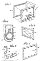
- FIGS 1, 2 and 4 illustrate an annular stretcher frame assembly 10 embodying features of the invention.
- the stretcher frame 10 assembly comprises frame sections 11 interconnected by means of elbows 12.
- a plurality of clips 13 secure fabric 14 onto the ridge elements 15 on the inner side of frame sections 11.
- Figures 1 and 2 best illustrate securing the fabric 14 to the ridge 15 by means of the spring clips 13.
- the ridge 15 projects inwardly toward the centre of the annular frame 10 and is generally parallel to the plane thereof.
- the fabric 14 is mounted on frame 10 with the clips 13 positioned out of the way so that they do not become disengaged from the ridge 15, or otherwise interfere with the subsequent handling of the stretcher frame assembly 10. Slight deviations from the parallel relationship could be accommodated provided that the ridge 15 or clip 13 do not project beyond the back plane of the frame assembly 10.
- FIG. 5 An alternative frame section 20 is shown in Figure 5 which has a plurality of ridges or projections 21 along the length thereof in those areas where the spring clips 13 are to be used to secure the fabric 14 to the ridges 21.
- Figures 2 and 3 illustrate the stretcher frame assembly 10 with fabric 14 mounted thereon in conjunction with a display frame 30.
- the inner surface or contact points of the display frame 30 match the outer surface of the stretcher frame assembly 10 so that the fabric 14 can be displayed while still mounted on the stretcher frame 10.
- Suitable means are provided along the outer edge of the display frame 30 to fit over the back side of the stretcher frame 10 to hold the stretcher frame assembly 10 and the display frame 30 together.
- the mountings of the edges of the fabric 14 to the ridges 15 by means of clips 13 are most important on those sides of the stretcher frame where the fabric is pulled tautly over the ridge 15 to put the proper tension on the fabric.
- Other means may be employed to initially mount the fabric on the opposite sides of the stretcher frame. With rectangular shaped frame assemblies at least two adjacent frame sections must be provided with inner ridges suitable for securing the fabric thereto by clips.
- the stretcher frame assembly 10 can be made as a breakdown unit comprising standard corner sections or elbows 12 with frame sections 11 of various lengths in order to form stretcher frames in a wide variety of sizes. It is also contemplated that the stretcher frame of the invention may take the shape other than rectangular, in which case the corner sections or elbows 12 may have an angle other than 90°. The ends of the corner sections or elbows 12 may be provided with ridges 35 which interfit grooves 36 provided on the interiors of the frame section 11 to properly lock the individual frame sections 11 into position with the elbows 12 when assembling the stretcher frame components to prevent relative rotation thereof.
- the stretcher frame 10 and the elbows 12 of the invention can be formed of any suitable plastic, metal or wood materials or combinations thereof.
- Plastic material such as polyethylene is preferred because it can be easily and inexpensively produced by extruding.
- the ridge can be extended integrally therein.
- the cross-section of the frame sections 11 while shown hollow and circular in the drawings, may be of any convenient cross-sectional shape and moreover, may be solid instead of hollow as shown.
- the ridge 15 is shown in the drawings as being integral with the frame section 11; however, the ridge may be a separate element and attached or fixed to the frame section 10 by suitable means.
- the stretcher frames of the invention are most suitable for use in art classes where the stretcher frames may be frequently reused by the students, particularly when the frames are made as breakdown units.
- clipping means have been described herein in terms of spring clips, it is obvious that different types of clipping means can be employed.
Landscapes
- Screen Printers (AREA)
Claims (4)
Applications Claiming Priority (2)
| Application Number | Priority Date | Filing Date | Title |
|---|---|---|---|
| US81919486A | 1986-01-14 | 1986-01-14 | |
| US819194 | 1986-01-14 |
Publications (2)
| Publication Number | Publication Date |
|---|---|
| EP0229636A1 EP0229636A1 (de) | 1987-07-22 |
| EP0229636B1 true EP0229636B1 (de) | 1991-06-05 |
Family
ID=25227456
Family Applications (1)
| Application Number | Title | Priority Date | Filing Date |
|---|---|---|---|
| EP19870100136 Expired EP0229636B1 (de) | 1986-01-14 | 1987-01-08 | Zusammengestellter Spannrahmen |
Country Status (2)
| Country | Link |
|---|---|
| EP (1) | EP0229636B1 (de) |
| DE (1) | DE3770479D1 (de) |
Families Citing this family (7)
| Publication number | Priority date | Publication date | Assignee | Title |
|---|---|---|---|---|
| DE69014662D1 (de) * | 1989-02-10 | 1995-01-19 | Colart Int Sa | Spannrahmenanordnung für Künstler. |
| IT1229870B (it) * | 1989-02-10 | 1991-09-13 | Renato Lucchetti | Telaio con tela componibile per pittori. |
| AU593512B3 (en) * | 1989-04-26 | 1990-02-08 | Robert Leslie Wakelin | Fabric stretch frame |
| US5287640A (en) * | 1992-06-12 | 1994-02-22 | Morgan Robert E | Excess material supporting strap for craft frame |
| US7191555B2 (en) | 2003-02-25 | 2007-03-20 | Hughes Robert P | Display panels |
| NL1034769C2 (nl) * | 2007-10-16 | 2009-04-20 | Johannes Hendrikus Ninaber | Spanraam voor in het bijzonder schildersdoek. |
| NL1035915C2 (nl) * | 2008-09-10 | 2009-08-12 | Michael Bernardus Joannes Post | Kunststof spieraam waarvan de spielatten en kruislatten uit drie cilindervormige holle delen bestaan welke plaats bieden aan de hoekverbindingen, kruisstukken en uitspiemechanisme waardoor een stabiele constructie ontstaat en de doekspanning snel aangepast kan worden. |
Family Cites Families (4)
| Publication number | Priority date | Publication date | Assignee | Title |
|---|---|---|---|---|
| GB357653A (en) * | 1930-07-01 | 1931-10-01 | Gilbert Witter West | Improvements in and relating to frames or stretchers for canvas or other material for artists' use |
| US3529653A (en) * | 1968-10-14 | 1970-09-22 | Edward C Fey Jr | Expandable frame for painting canvas |
| US3625274A (en) * | 1970-05-01 | 1971-12-07 | Universal Molding Co Inc | Adjustable frame for canvases |
| US3950869A (en) * | 1975-07-30 | 1976-04-20 | John Jacob Samarin | Stretcher frame |
-
1987
- 1987-01-08 DE DE8787100136T patent/DE3770479D1/de not_active Expired - Lifetime
- 1987-01-08 EP EP19870100136 patent/EP0229636B1/de not_active Expired
Also Published As
| Publication number | Publication date |
|---|---|
| DE3770479D1 (de) | 1991-07-11 |
| EP0229636A1 (de) | 1987-07-22 |
Similar Documents
| Publication | Publication Date | Title |
|---|---|---|
| US4451997A (en) | Stretcher frame for holding fabric | |
| US4947561A (en) | Frame for cloth or artistic canvases | |
| US4237632A (en) | Frame elements for releasably mounting a poster | |
| US8752312B2 (en) | Canvas stretching system with corner clamps | |
| CA1041129A (en) | Canvas stretcher frame | |
| US20180213950A1 (en) | Image display assembly and interlocking fastener thereof | |
| CA2732816C (en) | Adjustable canvas stretching assembly having adjustable stretching bars | |
| EP0229636B1 (de) | Zusammengestellter Spannrahmen | |
| US6962017B1 (en) | Framing system for securing and displaying flat sheet materials | |
| US5133140A (en) | Frame with fabric securing toothed strips or moldings and method | |
| US3127695A (en) | Canvas stretching frame | |
| US3996682A (en) | Self contained frame | |
| US4860814A (en) | Stretcher frame assembly | |
| US4329716A (en) | Combination television picture projection screen unit and ornamental cover unit therefor | |
| US3886990A (en) | Integral universal stretcher bar | |
| US5987789A (en) | Stitchery stand and frame | |
| CA1337238C (en) | Framing system and component parts thereof | |
| US6675510B2 (en) | Fabric-gripping/stretching system | |
| EP0382127B1 (de) | Spannrahmenanordnung für Künstler | |
| US5115584A (en) | Artist's sectional stretcher with canvas | |
| US4237630A (en) | Picture frame assembly | |
| US3823499A (en) | Adjustable frame | |
| JP3013637U (ja) | シート状表示材の張設構造 | |
| US20050229446A1 (en) | System for securing fabric to a quilting bar | |
| GB2264056A (en) | Frame for supporting canvas |
Legal Events
| Date | Code | Title | Description |
|---|---|---|---|
| PUAI | Public reference made under article 153(3) epc to a published international application that has entered the european phase |
Free format text: ORIGINAL CODE: 0009012 |
|
| AK | Designated contracting states |
Kind code of ref document: A1 Designated state(s): DE FR GB IT |
|
| 17P | Request for examination filed |
Effective date: 19880314 |
|
| 17Q | First examination report despatched |
Effective date: 19890918 |
|
| ITF | It: translation for a ep patent filed | ||
| GRAA | (expected) grant |
Free format text: ORIGINAL CODE: 0009210 |
|
| AK | Designated contracting states |
Kind code of ref document: B1 Designated state(s): DE FR GB IT |
|
| REF | Corresponds to: |
Ref document number: 3770479 Country of ref document: DE Date of ref document: 19910711 |
|
| RAP2 | Party data changed (patent owner data changed or rights of a patent transferred) |
Owner name: VILMANN, MARGARET J.D. Owner name: VILMANN, JAMES R. |
|
| ET | Fr: translation filed | ||
| PLBE | No opposition filed within time limit |
Free format text: ORIGINAL CODE: 0009261 |
|
| STAA | Information on the status of an ep patent application or granted ep patent |
Free format text: STATUS: NO OPPOSITION FILED WITHIN TIME LIMIT |
|
| 26N | No opposition filed | ||
| PGFP | Annual fee paid to national office [announced via postgrant information from national office to epo] |
Ref country code: GB Payment date: 19960104 Year of fee payment: 10 |
|
| PGFP | Annual fee paid to national office [announced via postgrant information from national office to epo] |
Ref country code: FR Payment date: 19960109 Year of fee payment: 10 |
|
| PGFP | Annual fee paid to national office [announced via postgrant information from national office to epo] |
Ref country code: DE Payment date: 19960115 Year of fee payment: 10 |
|
| PG25 | Lapsed in a contracting state [announced via postgrant information from national office to epo] |
Ref country code: GB Effective date: 19970108 |
|
| GBPC | Gb: european patent ceased through non-payment of renewal fee |
Effective date: 19970108 |
|
| PG25 | Lapsed in a contracting state [announced via postgrant information from national office to epo] |
Ref country code: FR Effective date: 19970930 |
|
| PG25 | Lapsed in a contracting state [announced via postgrant information from national office to epo] |
Ref country code: DE Effective date: 19971001 |
|
| REG | Reference to a national code |
Ref country code: FR Ref legal event code: ST |
|
| PG25 | Lapsed in a contracting state [announced via postgrant information from national office to epo] |
Ref country code: IT Free format text: LAPSE BECAUSE OF NON-PAYMENT OF DUE FEES;WARNING: LAPSES OF ITALIAN PATENTS WITH EFFECTIVE DATE BEFORE 2007 MAY HAVE OCCURRED AT ANY TIME BEFORE 2007. THE CORRECT EFFECTIVE DATE MAY BE DIFFERENT FROM THE ONE RECORDED. Effective date: 20050108 |