EP0229687A2 - Herstellungsverfahren von Halbleiter-Scheiben - Google Patents
Herstellungsverfahren von Halbleiter-Scheiben Download PDFInfo
- Publication number
- EP0229687A2 EP0229687A2 EP87300050A EP87300050A EP0229687A2 EP 0229687 A2 EP0229687 A2 EP 0229687A2 EP 87300050 A EP87300050 A EP 87300050A EP 87300050 A EP87300050 A EP 87300050A EP 0229687 A2 EP0229687 A2 EP 0229687A2
- Authority
- EP
- European Patent Office
- Prior art keywords
- ingot
- structures
- semiconductor material
- mounting
- manufacturing wafers
- Prior art date
- Legal status (The legal status is an assumption and is not a legal conclusion. Google has not performed a legal analysis and makes no representation as to the accuracy of the status listed.)
- Granted
Links
- 239000000463 material Substances 0.000 title claims abstract description 56
- 239000004065 semiconductor Substances 0.000 title claims abstract description 54
- 235000012431 wafers Nutrition 0.000 title claims abstract description 47
- 238000004519 manufacturing process Methods 0.000 title claims abstract description 39
- 238000000034 method Methods 0.000 abstract description 31
- 238000012545 processing Methods 0.000 abstract description 15
- 229910003460 diamond Inorganic materials 0.000 description 7
- 239000010432 diamond Substances 0.000 description 7
- 230000001788 irregular Effects 0.000 description 7
- 239000013078 crystal Substances 0.000 description 5
- 230000003993 interaction Effects 0.000 description 5
- 210000002445 nipple Anatomy 0.000 description 5
- 239000002245 particle Substances 0.000 description 5
- 238000007670 refining Methods 0.000 description 5
- 229920000515 polycarbonate Polymers 0.000 description 3
- 239000004417 polycarbonate Substances 0.000 description 3
- 239000002699 waste material Substances 0.000 description 3
- 238000013459 approach Methods 0.000 description 2
- 230000000875 corresponding effect Effects 0.000 description 2
- 230000013011 mating Effects 0.000 description 2
- 238000002231 Czochralski process Methods 0.000 description 1
- 239000004593 Epoxy Substances 0.000 description 1
- 229920004142 LEXAN™ Polymers 0.000 description 1
- 239000004418 Lexan Substances 0.000 description 1
- XUIMIQQOPSSXEZ-UHFFFAOYSA-N Silicon Chemical compound [Si] XUIMIQQOPSSXEZ-UHFFFAOYSA-N 0.000 description 1
- 230000015572 biosynthetic process Effects 0.000 description 1
- 238000004040 coloring Methods 0.000 description 1
- 150000001875 compounds Chemical class 0.000 description 1
- 238000007796 conventional method Methods 0.000 description 1
- 229910021419 crystalline silicon Inorganic materials 0.000 description 1
- 238000005520 cutting process Methods 0.000 description 1
- 230000000694 effects Effects 0.000 description 1
- 239000000945 filler Substances 0.000 description 1
- 238000010348 incorporation Methods 0.000 description 1
- 230000000977 initiatory effect Effects 0.000 description 1
- 230000002452 interceptive effect Effects 0.000 description 1
- 238000005259 measurement Methods 0.000 description 1
- 229910021421 monocrystalline silicon Inorganic materials 0.000 description 1
- 230000002093 peripheral effect Effects 0.000 description 1
- 230000000630 rising effect Effects 0.000 description 1
- 229910052710 silicon Inorganic materials 0.000 description 1
- 239000010703 silicon Substances 0.000 description 1
- 238000010561 standard procedure Methods 0.000 description 1
- 239000007858 starting material Substances 0.000 description 1
Images


Classifications
-
- B—PERFORMING OPERATIONS; TRANSPORTING
- B28—WORKING CEMENT, CLAY, OR STONE
- B28D—WORKING STONE OR STONE-LIKE MATERIALS
- B28D5/00—Fine working of gems, jewels, crystals, e.g. of semiconductor material; apparatus or devices therefor
- B28D5/0058—Accessories specially adapted for use with machines for fine working of gems, jewels, crystals, e.g. of semiconductor material
-
- B—PERFORMING OPERATIONS; TRANSPORTING
- B28—WORKING CEMENT, CLAY, OR STONE
- B28D—WORKING STONE OR STONE-LIKE MATERIALS
- B28D5/00—Fine working of gems, jewels, crystals, e.g. of semiconductor material; apparatus or devices therefor
- B28D5/02—Fine working of gems, jewels, crystals, e.g. of semiconductor material; apparatus or devices therefor by rotary tools, e.g. drills
- B28D5/022—Fine working of gems, jewels, crystals, e.g. of semiconductor material; apparatus or devices therefor by rotary tools, e.g. drills by cutting with discs or wheels
-
- C—CHEMISTRY; METALLURGY
- C30—CRYSTAL GROWTH
- C30B—SINGLE-CRYSTAL GROWTH; UNIDIRECTIONAL SOLIDIFICATION OF EUTECTIC MATERIAL OR UNIDIRECTIONAL DEMIXING OF EUTECTOID MATERIAL; REFINING BY ZONE-MELTING OF MATERIAL; PRODUCTION OF A HOMOGENEOUS POLYCRYSTALLINE MATERIAL WITH DEFINED STRUCTURE; SINGLE CRYSTALS OR HOMOGENEOUS POLYCRYSTALLINE MATERIAL WITH DEFINED STRUCTURE; AFTER-TREATMENT OF SINGLE CRYSTALS OR A HOMOGENEOUS POLYCRYSTALLINE MATERIAL WITH DEFINED STRUCTURE; APPARATUS THEREFOR
- C30B33/00—After-treatment of single crystals or homogeneous polycrystalline material with defined structure
Definitions
- the field of the invention pertains to methods of manufacturing semiconductor devices, such as solar cells, and in particular, to methods of manufacturing wafers of semiconductor material used in manufacturing semiconductor devices.
- One conventional approach to providing wafers for such solar cells involves grinding an ingot into a round shape and then sawing pairs of opposed elongated planes along the ingot.
- the ingot, as grown, of course has a curved surface along its direction of elongation. However, the surface is somewhat irregular.
- the ingot is clamped for the above grinding. Attempting to position the ingot in the clamps to reduce wastage in grinding from the irregular to the round shape is typically a far from ideal process.
- feelers along the apparatus help the operator approximately determine the optimal position for the ingot in the clamps to minimize the amount of material ground off in providing the round shape.
- U.S. Patent No. 4,487,989 assigned to the present applicant reveals some helpful variations in, for example, the process just described. Specifically, it reveals the advantages which can be garnered from slabbing the ingot to provide the pairs of opposed planes first and, then, grinding the corner regions to round them off, to flatten them, or, alternatively, eliminating that grinding altogether and leaving the corner regions irregular. However, the difficulty and wastage resulting from the inaccuracies in positioning the ingot for slabbing and grinding, remained unaddressed.
- the present invention significantly addresses this area of concern.
- a method of manufacturing wafers of semiconductor material includes the steps of: providing an elongated ingot of semiconductor material having a curved surface along the direction of elongation; mounting a structure for ingot mounting on each of the end surfaces of the ingot; positioning the ingot mounting structures on fixture structures to mount the ingot; and rotating the mounted ingot.
- the method incorporates ease of performance, significant savings in material, and the capability for readily meeting desired tolerances for semiconductor wafers.
- the positioned ingot mounting structures are released and the ingot is removed from the fixture structures; however, the mounting structures, later, are positioned on fixture structures a second time to mount the ingot, and a rotating of the ingot is again carried out.
- each ingot mounting structure In positioning the ingot mounting structures, at each of the end surfaces of the elongated ingot, a marking operation is carried out, along the straight paths between the positions at such surfaces, of node lines along the ingot.
- the mounting of each ingot mounting structure then involves centering the structure substantially on the intersection of these described paths. Specifically, notches defined by the mounting structure are aligned substantially along such paths to accomplish this centering.
- the shapes of the ingot mounting structures and of the fixture structures on which they are positioned, are important in achieving the desired centering and alignment of the ingot as mounted for processing. Specifically, substantially spherical surface portions of the ingot mounting structures are positioned against substantially conical surface portions of the fixture structures.
- the end surfaces of the ingot, substantially is grown are sawed off at least approximately perpendicularly to the direction of elongation of the ingot to define modified end surfaces at least approximately perpendicular to such direction of elongation.
- the ingot mounting structures are then mounted on these modified end surfaces.
- the ingot is concurrently sawed along its direction of elongation at, at least a first pair of positions to provide a first pair of at least approximately parallel elongated ingot surfaces; the mounted ingot is rotated through an angle of substantially 90 degrees; then the ingot is again concurrently sawed along its direction of elongation at, at least a second pair of positions to provide a second pair of at least approximately parallel elongated ingot surfaces, such second pair of elongated ingot surfaces being at least approximately perpendicular to the first pair.
- the referenced positions for such sawing are selected to leave, after the sawing, curved ingot surface portions between the pairs of elongated ingot surfaces.
- the curved ingot surface portions remaining after the sawing to provide the pairs of elongated ingot surfaces, are ground in order to round them off, the mounted ingot undergoing a continual rotation in the course of such grinding.
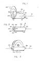
- FIG. 1 sawing-off ingot end surfaces
- FIG. 3 sawing along the ingot to provide elongated surfaces
- FIG. 5 grinding remaining curved ingot surfaces between the elongated surfaces to round them off
- FIG. 6 scrapeatedly sawing through the ingot transverse to the direction of elongation to provide wafers.
- FIG. 2 The mounting of ingot mounting structures employing ingot node lines for centering purposes is illustrated in FIG. 2.
- the detailed forms of two types of mounting structures are shown in FIGS. 11A-11C (with lugs for rotationally driving the ingot) and FIGS. 12A-12C (without such lugs).
- the inward arrows against the ingot mounting structures indicate the force of the applicable end fixture structures for mounting the ingot (those of FIG. 7 in respect to the processing of FIG. 3 and those of FIG. 8 in respect to the processing of FIG. 5).
- These different forms of fixture structures exemplify the types of differences which might typically exist while the structure which interacts with the ingot mounting structures remains essentially the same.
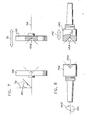
- FIG. 4 An additional grinding process to further refine the elongated ingot surfaces is illustrated in FIG. 4. This may be employed, in some circumstances, if additional accuracy is indicated to be necessary or desired.
- FIG. 1 there is shown a single crystal ingot 12 of semiconductor material. It could well be of a variety of different kinds of such material. However, for convenience of description and ease of understanding, the ingot will be assumed to be made of crystalline silicon, doped so as to be of P-type conductivity, and particularly adapted for manufacturing wafers to be used in producing single crystal silicon solar cells.
- Such ingots are most typically grown by the well-known Czochralski process with a pre-determined type of crystal orientation.
- the ingot 12 has been formed with a [100] type of crystal orientation.
- the ingot 12 has a curved elongated surface 14 along the direction of elongation and left and right end surfaces 16 and 20 (with reference to the view of FIG. 1).
- the ingot is shown in FIG. 1 substantially as grown (and removed from ingot growth apparatus).
- the direction of elongation is represented by the axial line 21 through the ingot for growth of the ingot (e.g. according to the Czochralski method which incorporates rotation about such an axis in growing the ingot).
- the curved elongated surface 14 provides roughly circular-shaped, but somewhat irregular cross-sections perpendicular to the direction of elongation. The irregular aspect, of course, is a natural consequence of the growth process.
- the single crystal structure of the ingot 12 comes together to form well-defined node lines along outer surfaces of the ingot.
- the crystallographic characteristics of the growth determine that such lines are 90 degrees apart along outer surfaces of the ingot -- running along the main curved surface 14 as well as along at least the left (starter) one 16 of the two end surfaces.
- One such node line 22 shows up, almost completely, in the view of FIG. 1.
- Two end surface portions 24, along the left end surface 16, of two additional node lines, also appear in FIG. 1.
- the portion 26 of one of the latter node lines remaining after the end sawing of FIG. 1, is shown in FIG. 2, in which the ingot is rotated somewhat with respect to the view of FIG. 1.
- the node lines quite commonly may not appear along all or part of the right (finisher) end surface 20. The reason is that some structure at that end is quite commonly lost in the process of finishing the growth and removing the ingot from the growth apparatus.
- the left end surface 16 of the ingot 12 is being sawed off by movement of the ingot upwardly against a conventional rotating saw blade 28, charged along its cutting edge with diamond particles.
- Such sawing provides a modified left end surface 30 (FIG. 2) which is approximately perpendicular to the direction of elongation of the ingot. In the ideal, this surface would be exactly perpendicular to that direction. But due to limitations in equipment and alignment, some meaningful error typically is a reality. The existence of such error is one reason for the advantages achieved with the present process.
- the upward movement arrow 32 of FIG. 1, of course, represents the upward movement of the ingot in accomplishing the end sawing.
- the ingot After the sawing off of the left end surface 16, the ingot is moved lengthwise, and in similar fashion, the right end surface 20 is sawed-off to leave a modified right end surface (not shown) also approximately perpendicular to the direction of elongation of the ingot.
- the saw could be moved downardly through the ingot in achieving the sawing-off, as opposed to the ingot moving upwardly against the saw.
- the ingot might be supported in a series of V-shaped supports therealong, with undesirable tilting of the ingot in the vertical direction being avoided by setting the positions of the V-shaped structures with regard to a reference plane. Undesirable "tilting" of the ingot along the horizontal direction may also be tempted to be minimized by attempting to vertically align node lines along the ingot end surfaces.
- FIG. 2 there is shown the ingot 12 having a lugged ingot mounting structure 34 mounted on the modified left ingot end surface 30 (see also FIGS. 11A-11C), and having a similar, but unlugged ingot mounting structure 36 mounted on the modified right end surface (see also FIGS. 12A-12C).
- FIG. 2 The method of centering the ingot mounting structures, for such mounting, is illustrated in FIG. 2, with reference to the detailed forms of the mounting structures, as shown in FIGS. 11A-11C and 12A-12C.
- a pair of straight intersecting lines have been scribed (with a sharp tool appropriate for such scribing) along with the modified left end surface 30 of the ingot.
- a first scribe line 40 connecting the end positions 42 of two opposed ingot node lines
- a second scribe line 44 connecting the end positions 46 of the second pair of ingot node lines.
- the lugged ingot mounting structure 34 has been mounted (using a standard epoxy material, such as that sold by Loctite under its Designation No. 422) with its center position 47 over the point of intersection of the two scribe lines.
- Such is accomplished by aligning opposed notches 48 in the mounting structure along the scribe lines.
- the mounting process for the unlugged ingot mounting structure 36 on the modified right ingot end surface is comparable, including the scribing of comparable scribe lines and placing the center position 50 of the structure over the intersection of such lines utilizing alignment of opposed notches 52 defined by the unlugged mounting structures.
- the opposed notches, defined by each mounting structure, as shown, are 180° apart along the mounting structure.
- the lugged ingot mounting structure 34 has a hemispherical upper surface 53, apart from the breaks in the hemispherical shape therealong, resulting from a pair of lugs 54 projecting from such surface and the four notches 48 along the surface.
- the notches are formed in the dome-shaped wall structure presenting the generally hemispherically-shaped upper surface.
- the thickness of that wall structure is essentially unchanged from the base through the top.
- the base surfaces 62 of the lugs, as shown, form part of the base of the structure as a whole.
- the spherical shape, in itself, is an inherently strong configuration.
- the internal wall structure adds significant further strength.
- the unlugged ingot mounting structure 36 its form is comparable to that for the lugged ingot mounting structure, as just described, apart from the absence of the projecting lugs.
- such strength is of substantial importance when the ingot mounting structures are tightly mounted with substantial inward force in fixture structures such as those of FIG. 7 and FIG. 8.
- the end fixture structures of FIG. 7 include an end fixture structure 68 for receiving the lugged ingot mounting structure 34, and an end fixture structure 70 for receiving the unlugged ingot mounting structure 36 (left and right end fixture structures, respectively, with reference to the view of FIG. 7). These end fixture structures are incorporated into ingot mounting and rotating apparatus otherwise constructed along conventional lines. As indicated by the two-headed arrow of FIG. 7, the right end fixture structure can be moved by the apparatus toward and away from the left end fixture structure along a fixed center line 74 for the apparatus. This, of course, is to clamp and unclamp an ingot in position. The left end fixture structure, on the other hand, does not incorporate that capability for movement.
- the apparatus provides this end fixture structure with the capability of being turned through an accurately defined angle of 90 degrees and then solidly and stably locked with the ingot in position in the end fixtures.
- the right end fixture structure 70 through a rotational mounting in the apparatus, is free to rotate the 90 degrees also.
- the seating of the ingot mounting structures in the end fixture structures 68 and 70 is well-illustrated by reference to FIGS. 7, 9A-B and 10.
- FIGS. 9A and 9B showing front views of the end fixture structures of FIG. 7, and referring first to the left end fixture structure 68, there is a central region surface which is conical, apart from an opening 84 for a nipple cavity 86 (see FIG. 10) at the apex, and apart from two slots which extend into the central region.
- the nipple cavity is to collect undesirable particles and the like which might tend to interfere with the desired seating of an ingot mounting structure in the fixture structure.
- the two slots are a left slot 88 and a right slot 90 with reference to the view of FIG. 9A. As is evident in FIG. 9A and FIG.
- the left end fixture structure also has a planar outer surface region 96.
- the right end fixture structure 70 has a central region surface 100 that is essentially the same as the central region surface of the left end fixture structure except for the absence of slots.
- the central region surface for the right end fixture has a conical shape, solely apart from an opening 102, at the apex, for a nipple cavity 104 (FIG. 7) which is essentially the same as the nipple cavity for the left end fixture structure.
- the right end fixture structure also has a planar outer surface region 106 that is essentially the same as the corresponding region for the left end fixture structure, apart from the absence of the slots for the right end fixture structure.
- the shapes and relationships essentially serve to center the ingot in a manner desirable for processing even where the modified left end surface 30 and the modified right end surface 108 are somewhat off their ideal perpendicular orientations with respect to the direction of elongation of the ingot. That direction of elongation, as previously noted, is represented by the axial line 21 of FIG. 1 (the nominal center line for the ingot as it is grown).
- the position 112 of the intersection of the scribe lines 40 and 42 along the modified left end surface 30 is indicated in FIG. 10.
- the position 114 of the intersection of corresponding scribe lines along the modified right end surface is also shown.
- the interaction of the spherical and conical shapes serve to essentially place these positions along the center line 74 for the end fixture structures even when there is a degree of error in the desired perpendicular orientation of the modified end surfaces with respect to the direction of elongation.
- it serves to essentially center the ingot in the end fixture structures, and thus in the apparatus of which the end fixture structures are a part, for processing the ingot in the apparatus. This is considered to be an extremely desirable way to position the ingot so as to reduce waste of valuable ingot material in the processing of the ingot.
- the depth of the lugs is significantly less than the depth of the slots 88 and 90 of the left end fixture structure 68.
- the reason for this is to assure that the clamping of the ingot is through the abutting interaction of the spherical surface portions of the ingot mounting structures and the conical surface portions of the end fixture structures, without interference from the lugs.
- seating of the lugs against the bottom of the slot is avoided.
- there is a tolerance in the off-perpendicular character of the modified ingot end surfaces which, if exceeded, is beyond the capability of the ingot mounting structures and end fixture structures. For example, if the modified left end surface were too far off the perpendicular, one of the lugs typically might seat against the bottom of one of the slots, thus interfering with the desired alignment capability of the ingot mounting structures and end fixture structures.
- ingot mounting structures having concave conical surface portions could be employed with end fixture structures having convex spherical surface portions.
- spherical surface portions could be employed on both, concave on one and convex on the other, in accordance with the same principle.
- practical difficulties are much greater with spherical surface portions on both.
- the actual abutting surface is of a ring-like shape. From a practical standpoint, this is considered advantageous over an actual abutting surface that would be of a spherical shape in the case of abutting spherical surface portions.
- the ingot is clamped (as is schematically shown) in the end fixture structures 68 and 70 of two-bladed slabbing apparatus to concurrently saw the ingot along its direction of elongation to provide planar elongated ingot surfaces.
- the apparatus has two saw blades which turn concurrently on a single shaft.
- the saw blades are conventionally charged with diamond particles, as typical in sawing semiconductor material.
- FIG. 3 illustrates the sawing, at one pair of positions, along the direction of elongation to provide one pair of at least approximately parallel elongated ingot surfaces.
- the saw blades typically angle outwardly somewhat as they saw through an ingot in the manner of Figure 3. As the blades grow older, this generally becomes more pronounced. That, by way of example, is one typical, potentially significant form of error which is encountered in achieving ideal parallel ingot surfaces.
- the ingot is rotated 90 degrees. Then the rotated ingot is again moved through the rotating saw blades. Thus, the ingot is sawed along the direction of elongation, at another pair of positions, to provide another pair of approximately parallel elongated ingot surfaces which are approximately perpendicular to the initially cut surfaces.
- FIG. 4 that figure illustrates a refining of the cut elongated ingot surfaces which can be performed if the surfaces are beyond the tolerances required after the sawing by the two-bladed saw. Whether the step of FIG. 4 is performed can vary from ingot to ingot. Also, as already indicated, as the blades grow older, there is a greater likelihood that the step of FIG. 4 will be performed.
- FIG. 4 shows the ingot 12 just as the further refining is being initiated.
- the shape of the cut ingot thus is well evident.
- the positions of sawing were selected to leave curved ingot surface portions 124 between the planar elongated surfaces. This leaving of such portions, along with the performing of the sawing of FIG. 3 before grinding the curved elongated ingot surface 14 (FIG. 1) to round off its irregularities, is a significant factor in reducing the waste of the valuable semiconductor material.
- a tolerance of about 0.13 mm (5 mils) in the desired orientation of a cut elongated ingot surface is considered acceptable.
- an adjacent corner should be about 0.13 mm (5 mils) or less away from the position where it would be for an ideally oriented plane.
- FIG. 4 is a conventional surface grinding to thus enhance the parallel relationships of the opposed, cut surfaces and the perpendicular relationship between the two pairs of such surfaces. It employs standard apparatus having a wheel 126 carrying a diamond refining ring 128. The wheel, as indicated by the arrows, is moved downward, pushing the ring against the surface to be refined and is rotated while the ingot, in a generally L-shaped holder 130, is held with a clamping force represented by the clamping arrow 132 along another surface. The holder is held to a rotating base 134 by magnetic force between the base and the holder.
- FIG. 8 The rounding off of the irregular curved elongated ingot surface portions 124 is illustrated in FIG. 5.
- End fixture structures for grinding apparatus used for this purpose are shown in FIG. 8. Apart from the end fixture structures, such grinding apparatus is constructed along conventional lines.
- the end fixture structures for the grinding operation do have a somewhat different appearance than those for the slabbing operation, in the respects relevant herein, they are essentially the same.
- the right end fixture structure 140 has the capability for axial movement, as indicated by the movement arrow 142, to accomplish the clamping of the ingot.
- the left end fixture structure does not have such capability; however, as indicated by the rotational arrow 144, it is the fixture structure for rotationally driving the ingot through the lugged ingot mounting structure which is mounted on this fixture structure.
- the rotational operation is a continuing rotation, one revolution after the next, rather than simply a rotation through 90 degrees, as in the slabbing operation.
- FIG. 10 The surfaces relevant to seating the ingot mounting structures against the grinder end fixture structures are essentially the same in all respects as those for the previously described end fixture structures for the slabbing apparatus.
- FIG. 10 shows the interaction between the ingot mounting structures and end fixture structures for the slabbing operation, in fact, shows equally well such interaction for the grinding operation.
- FIGS. 9A and 9B and the description thereof essentially are also equally applicable to the end fixture structures for the grinding, with two exceptions.
- One exception, readily evident in FIG. 8, is that the flat outer surface region for the grinder end fixture structures is of a much smaller size and the slots of the left structure correspondingly are of less length than in the case of the slabber fixture structures.
- different sizes (along with different thicknesses for the ends of the fixture structures which contain the relevant mounting surfaces) have been found convenient and practical for slabbing and grinding, and for incorporation in slabbing and grinding apparatus.
- each has a pair of opposed screw holes near the outside circumference. These holes are present in the event that, for some reason, the holding of the ingot in the slabbing apparatus is not sufficiently stable by virtue of clamping by the end fixtures alone. In that case, screws can be threaded through the screw holes into the end of the ingot to provide added stability. In practice, this has generally not been found to be necessary. Such screw holes are not even present in the end fixture structures for the grinding operation in that there is little likelihood that additional stability would be a requirement.
- the slot openings in the left end fixture structure 136 are readily apparent in FIG. 8, as are the conical surface portion 148 and nipple cavity 150 of the right end structure.
- the tapered portions of these structures, at their non-mounting ends are conventionallly constructed so that they fit, for rotational purposes, in conventional mating cavities for secure and stable rotation.
- the threaded structures simply, are to receive nuts which can be turned to force the end fixtures out when it is desired to move them from the tightly-fitting mating cavities in which they are mounted.
- the centerline (axis of rotation) for these end fixture structures is shown at 152 in FIGS. 8 and 5.
- the centerline 152 with regard to the view of FIG. 10, of course corresponds to the centerline 74 of that figure.
- FIG. 5 The grinding operation of FIG. 5 involves a standard rotating cup having a diamond grinding ring 156 at its grinding end. With the ingot rotating and moving along the axis for the apparatus, the cup is positioned so as to grind the irregular curved ingot surface portions 124 between the opposed elongated planar surfaces to a uniform round shape. The end result is ingot surface portions between planar surface portions that essentially, in cross-section, fall along a circle. As is apparent by reference to FIG. 5, this ordinarily entails grinding off small portions of the planar surfaces at their edges.
- the diamond cup may be positioned for a first pass by the ingot so as to approach the desired result. Then the ingot can be measured along the areas where no grinding occurred to determine how much closer the ingot should be moved to the cup to provide the uniform rounded surface.
- the first pass might involve a grinding set at in the range of about 1.5mm (60 mils) inward from the nominal position of the grown ingot surface. Then "room” for up to about an additional 1mm (40 mils) would be available for the second pass.
- the apparatus could readily be adapted so that the cup moves along the ingot rather than the ingot moving along the cup, to accomplish the desired grinding.
- the ingot 12 is shown in the process of having wafers 160 sliced therefrom in a further sawing operation.
- the ingot due to the processing which has been described, has one pair of essentially parallel elongated ingot surfaces 162, and another pair of such surfaces 164, essentially perpendicular to the first pair.
- the ingot also has regular, rounded corner regions 166 between the parallel surfaces.
- the shape of the wafers 160, as sliced off from the ingot then matches a desirable shape, e.g., for crystalline semiconductor solar cells. These wafers, of course, are ready for further processing into such solar cells or other semiconductor devices in accordance with well-known methods.
- FIG. 6 incorporates an inner diameter rotating saw blade 168 charged with diamond particles through which the ingot moves, to saw off the wafers.
- Such sawing operation and such sawing apparatus are fully conventional and well known.
- the saw blade could be moved through the ingot.
- other saw blades could be employed such as a conventional outer diameter saw blade charged with diamond particles.
- ingot mounting structures 34 and 36 a polycarbonate material has been found to be convenient and practical for use in forming the such structures. Such a polycarbonate sold under the trademark Lexan (General Electric) has been found to be satisfactory. Employing a black filler with the polycarbonate material, to color it black, also has been found to be convenient and helpful in giving the material coloring that facilitates viewing the ingot mounting structures.
- the ingot mounting structures are disposable in that they are used on one ingot and then disposed of. The material and cost of formation makes this disposable aspect eminently reasonable.
- off-perpendicular error in the sawing to provide the modified ingot end surfaces has been noted as being a significant area of concern, and an area in which the present process is advantageous.
- off-perpendicular error typically in the range of about 2mm (90 mils), and up to the range of about 5mm (200 mils), has been generally encountered. This refers to the distance off of a perpendicular position that one point along the outer edge of the surface might be with respect to an opposed point along such edge.
- the end fixture structure for the slabbing operation that is axially moved for clamping and unclamping
- it for example, can be formed with one peripheral portion having a flat rather than the circular edge. Then, for example, a flat plate on the associated apparatus can be slid over the flat portion when it is desired to prevent such rotation.
Landscapes
- Engineering & Computer Science (AREA)
- Mechanical Engineering (AREA)
- Chemical & Material Sciences (AREA)
- Crystallography & Structural Chemistry (AREA)
- Materials Engineering (AREA)
- Metallurgy (AREA)
- Organic Chemistry (AREA)
- Processing Of Stones Or Stones Resemblance Materials (AREA)
- Mechanical Treatment Of Semiconductor (AREA)
Applications Claiming Priority (2)
| Application Number | Priority Date | Filing Date | Title |
|---|---|---|---|
| US816923 | 1986-01-07 | ||
| US06/816,923 US4773951A (en) | 1986-01-07 | 1986-01-07 | Method of manufacturing wafers of semiconductor material |
Publications (3)
| Publication Number | Publication Date |
|---|---|
| EP0229687A2 true EP0229687A2 (de) | 1987-07-22 |
| EP0229687A3 EP0229687A3 (en) | 1989-02-15 |
| EP0229687B1 EP0229687B1 (de) | 1994-03-23 |
Family
ID=25221951
Family Applications (1)
| Application Number | Title | Priority Date | Filing Date |
|---|---|---|---|
| EP87300050A Expired - Lifetime EP0229687B1 (de) | 1986-01-07 | 1987-01-06 | Herstellungsverfahren von Halbleiter-Scheiben |
Country Status (4)
| Country | Link |
|---|---|
| US (1) | US4773951A (de) |
| EP (1) | EP0229687B1 (de) |
| JP (1) | JP2513477B2 (de) |
| DE (1) | DE3789393T2 (de) |
Cited By (3)
| Publication number | Priority date | Publication date | Assignee | Title |
|---|---|---|---|---|
| ITVI20080228A1 (it) * | 2008-10-01 | 2010-04-02 | Artimecc S R L | Procedimento per il taglio di barre in silicio per ridurle in filamenti |
| CN103434037A (zh) * | 2013-08-30 | 2013-12-11 | 天津市环欧半导体材料技术有限公司 | 一种多晶棒料车削夹具及车削方法 |
| CN111497043A (zh) * | 2020-03-05 | 2020-08-07 | 秦皇岛本征晶体科技有限公司 | 一种氟化镁波片元件的制作方法 |
Families Citing this family (16)
| Publication number | Priority date | Publication date | Assignee | Title |
|---|---|---|---|---|
| JP2903916B2 (ja) * | 1992-11-30 | 1999-06-14 | 信越半導体株式会社 | 半導体インゴット加工方法 |
| JP2789983B2 (ja) * | 1993-01-28 | 1998-08-27 | 信越半導体株式会社 | 加工誤差補正装置 |
| US5529051A (en) * | 1994-07-26 | 1996-06-25 | At&T Corp. | Method of preparing silicon wafers |
| JPH09509621A (ja) * | 1994-11-24 | 1997-09-30 | フィリップス エレクトロニクス ネムローゼ フェンノートシャップ | ドラム形状加工物を機械加工する方法、このような方法により製造されたドラム形状担体が設けられるx線診断装置及び写真複写機 |
| US5832914A (en) * | 1997-08-22 | 1998-11-10 | Seh America, Inc. | Ingot trimming method and apparatus |
| US5827111A (en) * | 1997-12-15 | 1998-10-27 | Micron Technology, Inc. | Method and apparatus for grinding wafers |
| US5827112A (en) * | 1997-12-15 | 1998-10-27 | Micron Technology, Inc. | Method and apparatus for grinding wafers |
| US6106365A (en) * | 1998-11-06 | 2000-08-22 | Seh America, Inc. | Method and apparatus to control mounting pressure of semiconductor crystals |
| ITMO20030336A1 (it) * | 2003-12-11 | 2005-06-12 | Gabriele Santi | Metodo per ottenere elementi laminari. |
| JP2007281210A (ja) * | 2006-04-07 | 2007-10-25 | Disco Abrasive Syst Ltd | 基板切断方法および基板切断装置 |
| JP2009178984A (ja) * | 2008-01-31 | 2009-08-13 | Jcm:Kk | シリコンインゴット用角切断バンドソー装置及びシリコンインゴットの加工方法 |
| US8425279B2 (en) * | 2008-09-30 | 2013-04-23 | Misubishi Polycrystalline Silicon America Corporation (MIPSA) | Apparatus for manufacturing seeds for polycrystalline silicon manufacture |
| JP5517156B2 (ja) * | 2010-03-18 | 2014-06-11 | 株式会社岡本工作機械製作所 | インゴットブロックの複合面取り加工装置 |
| JP5286329B2 (ja) * | 2010-06-18 | 2013-09-11 | 株式会社サンシン | シリコンブロック又は四角柱状部材の面取加工方法及びその装置 |
| DE102010063407A1 (de) * | 2010-12-17 | 2012-06-21 | Wacker Chemie Ag | Verfahren und Vorrichtung zur Herstellung von Silicium-Dünnstäben |
| TWI818617B (zh) * | 2021-08-09 | 2023-10-11 | 環球晶圓股份有限公司 | 晶棒治具組件與晶棒邊拋機台 |
Family Cites Families (6)
| Publication number | Priority date | Publication date | Assignee | Title |
|---|---|---|---|---|
| NL105904C (de) * | 1955-12-30 | |||
| DE1104074B (de) * | 1957-07-30 | 1961-04-06 | Telefunken Gmbh | Verfahren zum Zerschneiden eines Halbleiter-Einkristalles, z. B. aus Germanium, fuer Halbleiter-anordnungen in duenne Scheiben, deren Schnittflaechen senkrecht zu einer gewuenschten Kristallachse liegen |
| DE1066282B (de) * | 1958-03-26 | 1900-01-01 | ||
| US3802412A (en) * | 1972-06-08 | 1974-04-09 | Kayex Corp | Billet holder for cutting and slicing apparatus |
| US4331452A (en) * | 1980-08-04 | 1982-05-25 | Fairchild Camera And Instrument Corporation | Apparatus for crystal shaping |
| US4487989A (en) * | 1983-07-25 | 1984-12-11 | Atlantic Richfield Company | Contact for solar cell |
-
1986
- 1986-01-07 US US06/816,923 patent/US4773951A/en not_active Expired - Fee Related
-
1987
- 1987-01-06 EP EP87300050A patent/EP0229687B1/de not_active Expired - Lifetime
- 1987-01-06 JP JP62000258A patent/JP2513477B2/ja not_active Expired - Lifetime
- 1987-01-06 DE DE3789393T patent/DE3789393T2/de not_active Expired - Lifetime
Cited By (3)
| Publication number | Priority date | Publication date | Assignee | Title |
|---|---|---|---|---|
| ITVI20080228A1 (it) * | 2008-10-01 | 2010-04-02 | Artimecc S R L | Procedimento per il taglio di barre in silicio per ridurle in filamenti |
| CN103434037A (zh) * | 2013-08-30 | 2013-12-11 | 天津市环欧半导体材料技术有限公司 | 一种多晶棒料车削夹具及车削方法 |
| CN111497043A (zh) * | 2020-03-05 | 2020-08-07 | 秦皇岛本征晶体科技有限公司 | 一种氟化镁波片元件的制作方法 |
Also Published As
| Publication number | Publication date |
|---|---|
| JP2513477B2 (ja) | 1996-07-03 |
| JPS62190731A (ja) | 1987-08-20 |
| EP0229687B1 (de) | 1994-03-23 |
| DE3789393D1 (de) | 1994-04-28 |
| DE3789393T2 (de) | 1994-09-15 |
| US4773951A (en) | 1988-09-27 |
| EP0229687A3 (en) | 1989-02-15 |
Similar Documents
| Publication | Publication Date | Title |
|---|---|---|
| EP0229687B1 (de) | Herstellungsverfahren von Halbleiter-Scheiben | |
| US4344260A (en) | Method for precision shaping of wafer materials | |
| EP2226155B1 (de) | Zylinderschleifgerät und Zylinderschleifverfahren für Ingots | |
| CA1213865A (en) | Method of sawing crystalline rods, and multiple-blade internal-hole saw for carrying out the method | |
| EP3943645A1 (de) | Sic-kristallsubstrate mit optimaler orientierung von gitterebenen zur spaltreduzierung und herstellungsverfahren dafür | |
| US5845630A (en) | Process and apparatus for fabricating a semiconductor wafer | |
| US5529051A (en) | Method of preparing silicon wafers | |
| JP2002075923A (ja) | シリコン単結晶インゴットの加工方法 | |
| JP2008221351A (ja) | 芯出し位置決め装置およびそれを用いた芯出し位置決め方法 | |
| CN111730771B (zh) | 一种晶圆切割机 | |
| CN218658426U (zh) | 晶体毛坯研磨套筒夹具 | |
| CN215282771U (zh) | 一种硅片切割用定位装置 | |
| CN109366261A (zh) | 蝶形刀片的周边磨削工艺及装置 | |
| CN108620682A (zh) | 一种多边形切削工具 | |
| CN212683216U (zh) | 一种360°等分定位旋转夹具 | |
| JPH1133810A (ja) | 種結晶加工装置 | |
| KR20230096563A (ko) | 파이프 절단 및 절단부 면취 가공장치 | |
| CN221365275U (zh) | 一种大直径单晶硅棒剖方机金刚线切割定位装置 | |
| CN214978911U (zh) | 一种刀片夹具 | |
| CN120245233B (zh) | 一种晶圆透切装置及其使用方法 | |
| CN217122824U (zh) | 芯片切割刀的刀杆定位夹具 | |
| CN221111326U (zh) | 一种软刀改刀器 | |
| CN221495355U (zh) | 一种适配于内孔车工的导套夹持工装 | |
| CN217394062U (zh) | 一种可转位多工位金刚石切割夹具 | |
| CN2912899Y (zh) | 一种腰形截面工件对中夹具 |
Legal Events
| Date | Code | Title | Description |
|---|---|---|---|
| PUAI | Public reference made under article 153(3) epc to a published international application that has entered the european phase |
Free format text: ORIGINAL CODE: 0009012 |
|
| AK | Designated contracting states |
Kind code of ref document: A2 Designated state(s): DE FR GB IT NL |
|
| PUAL | Search report despatched |
Free format text: ORIGINAL CODE: 0009013 |
|
| AK | Designated contracting states |
Kind code of ref document: A3 Designated state(s): DE FR GB IT NL |
|
| 17P | Request for examination filed |
Effective date: 19890807 |
|
| RAP1 | Party data changed (applicant data changed or rights of an application transferred) |
Owner name: SIEMENS SOLAR INDUSTRIES L.P. |
|
| 17Q | First examination report despatched |
Effective date: 19910221 |
|
| GRAA | (expected) grant |
Free format text: ORIGINAL CODE: 0009210 |
|
| AK | Designated contracting states |
Kind code of ref document: B1 Designated state(s): DE FR GB IT NL |
|
| REF | Corresponds to: |
Ref document number: 3789393 Country of ref document: DE Date of ref document: 19940428 |
|
| ITF | It: translation for a ep patent filed | ||
| ET | Fr: translation filed | ||
| PLBE | No opposition filed within time limit |
Free format text: ORIGINAL CODE: 0009261 |
|
| STAA | Information on the status of an ep patent application or granted ep patent |
Free format text: STATUS: NO OPPOSITION FILED WITHIN TIME LIMIT |
|
| 26N | No opposition filed | ||
| REG | Reference to a national code |
Ref country code: GB Ref legal event code: IF02 |
|
| NLT1 | Nl: modifications of names registered in virtue of documents presented to the patent office pursuant to art. 16 a, paragraph 1 |
Owner name: SHELL SOLAR INDUSTRIES LP |
|
| REG | Reference to a national code |
Ref country code: FR Ref legal event code: CD |
|
| PGFP | Annual fee paid to national office [announced via postgrant information from national office to epo] |
Ref country code: FR Payment date: 20051122 Year of fee payment: 20 |
|
| PGFP | Annual fee paid to national office [announced via postgrant information from national office to epo] |
Ref country code: GB Payment date: 20051229 Year of fee payment: 20 |
|
| PGFP | Annual fee paid to national office [announced via postgrant information from national office to epo] |
Ref country code: NL Payment date: 20060127 Year of fee payment: 20 |
|
| PGFP | Annual fee paid to national office [announced via postgrant information from national office to epo] |
Ref country code: IT Payment date: 20060131 Year of fee payment: 20 |
|
| PGFP | Annual fee paid to national office [announced via postgrant information from national office to epo] |
Ref country code: DE Payment date: 20060201 Year of fee payment: 20 |
|
| PG25 | Lapsed in a contracting state [announced via postgrant information from national office to epo] |
Ref country code: GB Free format text: LAPSE BECAUSE OF EXPIRATION OF PROTECTION Effective date: 20070105 |
|
| PG25 | Lapsed in a contracting state [announced via postgrant information from national office to epo] |
Ref country code: NL Free format text: LAPSE BECAUSE OF EXPIRATION OF PROTECTION Effective date: 20070106 |
|
| REG | Reference to a national code |
Ref country code: GB Ref legal event code: PE20 |
|
| NLV7 | Nl: ceased due to reaching the maximum lifetime of a patent |
Effective date: 20070106 |