EP0229742A2 - Clapet inverseur de chauffage ou interrupteur de proximité - Google Patents
Clapet inverseur de chauffage ou interrupteur de proximité Download PDFInfo
- Publication number
- EP0229742A2 EP0229742A2 EP87630002A EP87630002A EP0229742A2 EP 0229742 A2 EP0229742 A2 EP 0229742A2 EP 87630002 A EP87630002 A EP 87630002A EP 87630002 A EP87630002 A EP 87630002A EP 0229742 A2 EP0229742 A2 EP 0229742A2
- Authority
- EP
- European Patent Office
- Prior art keywords
- valve
- valve element
- magnetic
- warm
- outlet
- Prior art date
- Legal status (The legal status is an assumption and is not a legal conclusion. Google has not performed a legal analysis and makes no representation as to the accuracy of the status listed.)
- Granted
Links
- 230000005291 magnetic effect Effects 0.000 claims abstract description 49
- 230000001143 conditioned effect Effects 0.000 claims description 21
- 230000000903 blocking effect Effects 0.000 claims description 7
- 238000004378 air conditioning Methods 0.000 claims description 5
- 239000012530 fluid Substances 0.000 claims description 5
- 230000001276 controlling effect Effects 0.000 claims 9
- 230000001105 regulatory effect Effects 0.000 claims 3
- 238000001816 cooling Methods 0.000 abstract description 16
- 238000010438 heat treatment Methods 0.000 abstract description 12
- 239000002184 metal Substances 0.000 description 4
- 229910052751 metal Inorganic materials 0.000 description 4
- 230000000740 bleeding effect Effects 0.000 description 2
- 239000012071 phase Substances 0.000 description 2
- RYGMFSIKBFXOCR-UHFFFAOYSA-N Copper Chemical compound [Cu] RYGMFSIKBFXOCR-UHFFFAOYSA-N 0.000 description 1
- 230000000295 complement effect Effects 0.000 description 1
- 230000006835 compression Effects 0.000 description 1
- 238000007906 compression Methods 0.000 description 1
- 230000008602 contraction Effects 0.000 description 1
- 229910052802 copper Inorganic materials 0.000 description 1
- 239000010949 copper Substances 0.000 description 1
- 230000000694 effects Effects 0.000 description 1
- 230000005294 ferromagnetic effect Effects 0.000 description 1
- 239000007791 liquid phase Substances 0.000 description 1
- 230000007774 longterm Effects 0.000 description 1
- 239000000696 magnetic material Substances 0.000 description 1
- 239000000463 material Substances 0.000 description 1
- 230000013011 mating Effects 0.000 description 1
- 238000013021 overheating Methods 0.000 description 1
- 239000004033 plastic Substances 0.000 description 1
- 229920003023 plastic Polymers 0.000 description 1
- 229920006264 polyurethane film Polymers 0.000 description 1
- 230000001932 seasonal effect Effects 0.000 description 1
- 239000007790 solid phase Substances 0.000 description 1
- 239000003351 stiffener Substances 0.000 description 1
- 238000011144 upstream manufacturing Methods 0.000 description 1
- 238000009423 ventilation Methods 0.000 description 1
- 238000010792 warming Methods 0.000 description 1
Images



Classifications
-
- G—PHYSICS
- G05—CONTROLLING; REGULATING
- G05D—SYSTEMS FOR CONTROLLING OR REGULATING NON-ELECTRIC VARIABLES
- G05D23/00—Control of temperature
- G05D23/185—Control of temperature with auxiliary non-electric power
- G05D23/1854—Control of temperature with auxiliary non-electric power with bimetallic element
-
- F—MECHANICAL ENGINEERING; LIGHTING; HEATING; WEAPONS; BLASTING
- F16—ENGINEERING ELEMENTS AND UNITS; GENERAL MEASURES FOR PRODUCING AND MAINTAINING EFFECTIVE FUNCTIONING OF MACHINES OR INSTALLATIONS; THERMAL INSULATION IN GENERAL
- F16K—VALVES; TAPS; COCKS; ACTUATING-FLOATS; DEVICES FOR VENTING OR AERATING
- F16K31/00—Actuating devices; Operating means; Releasing devices
- F16K31/02—Actuating devices; Operating means; Releasing devices electric; magnetic
- F16K31/06—Actuating devices; Operating means; Releasing devices electric; magnetic using a magnet, e.g. diaphragm valves, cutting off by means of a liquid
- F16K31/08—Actuating devices; Operating means; Releasing devices electric; magnetic using a magnet, e.g. diaphragm valves, cutting off by means of a liquid using a permanent magnet
- F16K31/086—Actuating devices; Operating means; Releasing devices electric; magnetic using a magnet, e.g. diaphragm valves, cutting off by means of a liquid using a permanent magnet the magnet being movable and actuating a second magnet connected to the closing element
-
- F—MECHANICAL ENGINEERING; LIGHTING; HEATING; WEAPONS; BLASTING
- F24—HEATING; RANGES; VENTILATING
- F24F—AIR-CONDITIONING; AIR-HUMIDIFICATION; VENTILATION; USE OF AIR CURRENTS FOR SCREENING
- F24F11/00—Control or safety arrangements
- F24F11/70—Control systems characterised by their outputs; Constructional details thereof
- F24F11/72—Control systems characterised by their outputs; Constructional details thereof for controlling the supply of treated air, e.g. its pressure
- F24F11/74—Control systems characterised by their outputs; Constructional details thereof for controlling the supply of treated air, e.g. its pressure for controlling air flow rate or air velocity
- F24F11/76—Control systems characterised by their outputs; Constructional details thereof for controlling the supply of treated air, e.g. its pressure for controlling air flow rate or air velocity by means responsive to temperature, e.g. bimetal springs
-
- G—PHYSICS
- G05—CONTROLLING; REGULATING
- G05D—SYSTEMS FOR CONTROLLING OR REGULATING NON-ELECTRIC VARIABLES
- G05D23/00—Control of temperature
- G05D23/19—Control of temperature characterised by the use of electric means
- G05D23/1925—Control of temperature characterised by the use of electric means using a combination of auxiliary electric and non-electric power
Definitions
- the thermostatic response is correct for cooling
- the supplying of heated air will encounter a minimum or no flow condition in an undercooled zone or area and dissatisfaction causing overheating if the zone temperature is above the cooling set point. Obviously, neither condition is satisfactory or energy efficient.
- the present invention is directed to a warm-up/changeover valve or proximity switch suitable for use in a system powered device in which air flow into a zone is controlled by the degree of bellows inflation which is in turn controlled by a thermostatic bleed valve.
- the warm-up/changeover valve or proximity switch can be either thermostatically responsive or solenoid actuated. If the use is to be for warm-up, a bleed line for deflating the bellows is opened when the valve is opened in response to the supplying of warm air or to the ceasing of the supplying of electrical power to the solenoid as due to the opening of a thermostatic switch. If a changeover function is required, the valve is configured as a valve with one outlet supplying air to the heating thermostat and one outlet supplying air to the cooling thermostat.
- thermostatically responsive valve or proximity switch for achieving a warm-up or changeover function in a conditioned air distributing system.
- a valve or proximity switch assembly is provided with an inlet, a normally open outlet and a normally closed outlet.
- a valve element is movable between two positions respectively blocking one of the two outlets. The movement of the valve element to the position closing the normally open outlet, and thereby opening the normally closed outlet, is responsive to the movement of a magnetic member into sufficient proximity to cause the valve element to snap over from one position to the other.
- the magnetic member is carried by an actuator which is moved in one embodiment responsive to a change in the temperature of the conditioned air being supplied and in another embodiment responsive to an electrical signal.
- FIG. 1 illustrates the use of the present invention in a warm-up configuration and is suitable for use with either actuator 150, 250 or 350 which will be described in more detail hereinafter.
- the numeral 10 generally designates an air distribution unit in which conditioned air is delivered from a central source thereof (not illustrated) to a plenum chamber 12 of the air distribution unit.
- a damper arrangement illustrated as inflatable bellows 14 and 15 regulates the flow of conditioned air from the plenum 12 to the area or space being conditioned.
- a portion of the conditioned air furnished to plenum chamber 12 flows through filter 20 where any foreign bodies entrained therein will be removed.
- the conditioned air passing through filter 20 is used for controlling the operation of unit 10.
- the control air passes from filter 20 to pressure regulator 30 via line 22.
- control air passes from regulator 30 into distributor 40 via line 38 and from distributor 40 via lines 41 and 42 to bellows 14 and 15, respectively. Additionally, control air passes via line 39 to bleed-type thermostat 50 which senses the temperature of the area to be conditioned and in response thereto controls the magnitude of the control signal supplied to bellows 14 and 15 by bleeding control air through bleed port 52 and the aperture 55 of apertured sliding plate 54.
- the common or inlet port 107 of valve assembly 100 is connected upstream of bleed port 52 via line 58.
- Normally open outlet 109 is capped by a cap 109a so that line 58 is normally blocked and has no influence on thermostat 50. Assuming that thermostat 50 is set for cooling an area, the slide plate 54 and therefore the inflation of bellows 14 and 15 will be adjusted accordingly.
- actuator 150 as illustrated, actuator 250, or thermostatic switch 180 of actuator 350 is exposed to the warm air in the plenum or the flowing air stream which causes the actuation of actuator 150 (or actuator 250, or the deactuation of actuator 350) which causes the flexure of blade 122 to the Figure 4 position due to the magnetic attraction between magnetic member 165 and magnetic pad 128.
- port 104 is uncovered so that bellows 14 and 15 are connected to atmosphere via lines 41 and 42, distributor 40, line 38, line 39, line 58 and outlet 105 which effectively bypasses/disables thermostat 50 such that bellows 14 and 15 deflate and warm air is delivered to the area independent of thermostat 50.
- FIG. 2 illustrates the use of the present invention in a cooling/heating changeover configuration and is suitable for use with actuator 150, 250 or 350.
- the numeral 10 generally designates an air distribution unit as described with respect to Figure 1 in which conditioned air flows through filter 20 to pressure regulator 30 via line 22 and passes from regulator 30 into distributor 40 via line 38. The air passes from distributor 40 via lines 41 and 42 to bellows 14 and 15, respectively. Additionally, control air passes via line 39 to common or inlet port 107 of valve assembly 100. Normally open outlet 109 is connected to cooling thermostat 70 via line 71 and normally closed outlet 105 is connected to heating thermostat 72 via line 73.
- Thermostats 70 and 72 are oppositely acting bleed thermostats such as is illustrated in Figure 1 and designated 50. They are oppositely acting in that cooling thermostat 70 controls the lowering of the room temperature to the set point whereas heating thermostat 72 controls the raising of the room temperature to the set point.
- the actuator 350 may have a switch 180 which may be of a thermostatic type and exposed to the plenum air or flowing air stream, or it may be a switch controlled by a computer or the like.
- the actuated and unactuated position of actuator 350 are the reverse of those of actuators 150 and 250.
- control air passes via line 39 to port 107, through valve assembly 100, out port 109 and passes via line 71 to cooling thermostat 70 which controls the inflation of bellows 14 and 15 as described above.
- actuator 350 is unactuated, control air will pass via line 39 to port 107, through valve assembly 100, out port 105 and will pass via line 73 to heating thermostat 72 which controls the inflation of bellows 14 and 15 as described above.
- Actuator 150 or 250 would similarly respond to the plenum air or flowing air stream so as to connect ports 107 and 109 in response to cool air and ports 107 and 105 in response to hot air but the designation of the actuated and unactuated positions would be reversed. If desired, the ports 109 and 105 could be connected to thermostats 72 and 70, respectively, if the heating mode was desired to be the actuated mode of actuator 350 or the unactuated mode of actuator 150 or 250. Where switch 180 is computer controlled, in addition to providing a changeover between heating and cooling, ventilation can be minimized in the case of a fire by causing the system to go over to the heating mode which would reduce the supplying of fresh air to the fire.
- valve assembly 100 is connected as shown in Figure 1 and powered by actuator 350
- an electric signal actuating actuator 350 will open port 105 to cause the bypassing of thermostat 50 and the deflating of bellows 14 and 15 providing maximum air circulation which is desired on the building floors above and below a fire.
- port 105 remains closed and the raised space temperature will cause the bellows 14 and 15 to inflate due to the stopping of bleed flow from thermostat 50 and thereby stop the flow of air to the space.
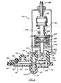
- the numeral 100 generally designates the valve assembly or proximity switch and the numeral 150 generally designates the actuator.
- the valve assembly 100 includes mating casing parts 102 and 103 which are of a non-magnetic material, such as plastic, and are glued or otherwise suitably secured together in a fluid tight assembly.
- Casing part 102 defines a normally closed port 104 which is fluidly connected to outlet 105.
- Casing part 103 defines port 106 and normally open port 108 which are, respectively, fluidly connected to inlet 107 and outlet 109.
- Casing part 103 further defines an extension 110 which has a cylindrical chamber 112 formed therein as well as an annular groove 114 and shoulder 116 formed on the exterior of the extension 110.
- a valve element 120 includes a flexible or pivotable blade 122 having one end received in a complementary recess 123 formed in casing part 102 so as to permit the locating and securing of valve element 120 in the assembling of casing parts 102 and 103.
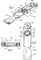
- Blade 122 has a stiffener in the form of a stepped turned up flange 124 as well as yoke assembly 126 and low reluctance ferro magnetic pad 128 secured thereto. As is best shown in Figures 7 and 8, blade 122 also has a necked down portion 125 which defines the point of flexure of blade 122.
- Yoke assembly 126 includes a polyurethane film disc 130 which alternatively seats on port 104 or port 108 in a valving action.
- yoke assembly 126 moves through an arc in moving between the positions blocking either port 104 or port 108, it is necessary to have the film disc 130 become co-planar with the seating face of ports 104 and 108.
- yoke 131 is provided with stepped diametrically extending pivot rods 132 as is best shown in Figures 8 and 9. Stepped pivot rods 132 are rotatably or pivotably received in mounting holes 127 in stepped turned up flange 124. Film disc 130 is held in place in yoke 131 by ring 133 which is press fit into yoke 131 with film disc 130 therebetween.
- Yoke 131 is therefore able to pivot into a co-planar engagement with port 104 or 108 and is moved to the co-planar engagement due to the unbalanced torsional force on the yoke 131 when film disc 130 is not co-planar and engages only one side thereof when engaging port 104 or 108.
- yoke assembly 126 one or both of the stepped turned up flanges 124 is bent towards flat a sufficient amount to permit yoke assembly 126 to be snapped into mounting holes 127 and the flange(s) returned to their original shape.
- Screw 136 is threadably secured in casing part 103 and engages blade 122 so as to provide a seating bias to cause film disc 130 to close port 104 as illustrated in Figure 5 in an unactuated position of actuator 150 or 250.
- the necked down portion 125 of blade 122 as is best shown in Figures 7 and 8, defines the pivot for flexure of blade 122 since it provides the least resistance to flexure.
- valve assembly or proximity switch 100 is secured in place by inserting extension 110 into hole 141 in sheet metal member 140 such that shoulder 116 engages sheet metal member 140.
- sheet metal member 140 is a member which may be installed in the wall of a plenum.
- a C-clip 142 or other suitable attachment means is placed in groove 114 and engages the opposite side of sheet metal member 140 as that engaged by shoulder 116.
- actuator 150 includes a charged thermostatic bellows 152 which is preferably of copper and filled with gas.
- Magnetic actuator 164 is secured to bellows 152 and carries a magnetic member 165 which is reciprocated in chamber 112 by the expansion and contraction of bellows 152 due to changes in the temperature of the warm or cool air stream to which it is exposed.
- Magnetic member 165 acts as a proximity switch with respect to magnetic pad 128 in that magnetic member 165 is not exposed to the fluid within the chamber 129 but causes the movement of film disc 130 in a valving action by attracting magnetic pad 128 when in proximity thereto.
- Figures 4 and 5 the structure of the valve assembly or proximity switch 100 is identical but Figure 4 illustrates the position of valve element 120 due to the magnetic attraction between magnetic member 165 and magnetic pad 128 whereas Figure 5 illustrates the unactuated position of valve element 120 due solely to the biasing effect of screw 136.
- the position of bellows 152 and therefore magnetic member 165 can be adjusted by screw 190.
- the valve assembly 100 is the same as that illustrated in Figures 3 and 4, but actuator 150 has been replaced with a different thermal actuator 250.
- the thermal actuator 250 is specifically illustrated as a phase change element 252 where a solid phase material goes to a liquid phase in the temperature range of interest and with an increase in volume, but could be a bimetal.
- compression spring 255 seats against stop 254 and cap member 256.
- Cap member 256 provides a seat for the head 258 of plunger 260 and is biased in opposition to spring 255 by spring 262 which seats against magnetic actuator 264 and head 258.
- Magnetic actuator 264 carries a magnetic member 265 which is reciprocated in chamber 112 by the actuator 250.
- the spring 262 serves as a lost motion device in that it absorbs overtravel of head 258 after magnetic actuator 264 has bottomed out in its movement within chamber 112.
- Spring 270 serves to return plunger 260 to the illustrated position when the output force is reduced in thermal element 252.
- the thermal element 252 located in the warm or cool air stream, senses the flowing air temperature and acts by changing phase, when appropriate. The position of thermal element 252 and therefore magnetic member 265 can be adjusted by screw 290.
- actuator 350 includes an internal spring solenoid 352 for positioning valve element 120 in response to an electric signal.
- the magnetic actuator 364 which carries magnetic member 365 is attached to the shaft of the solenoid. Upon energizing of the solenoid 352, magnetic member 365 is moved outwardly in chamber 112 causing outlet port 104 to close, as illustrated.
- the internal spring (not illustrated) causes the magnetic actuator 364 to move magnetic member 365 further into chamber 112 to thereby attract magnetic pad 128 causing valve disc 130 to engage and close port 108 and to open port 104.
- Power to solenoid 352 through contacts 353 is provided upon the closing of switch 180 which can be a thermostatically responsive switch or a computer controlled switch.
- the power source 300 can be any suitable source of power and may be incorporated into a computer control.
- valve assembly 100 is identical in Figures 3-6 Figures 5 and 6 show valve element 120 in the same position closing port 104.
- Figure 5 is a cold or an unactuated position of actuator 250 and
- Figure 6 is an actuated position of actuator 350.
- the difference in designation is due to the fact that energy in the form of heat is necessary to expand/acutate the actuators 150 and 250 whereas electrical energy is necessary to contact/actuate actuator 350.
- Figure 4 shows the valve element 120 in its actuated position closing port 108.
- the solenoid 352 is actuated in response to the completing of an electric circuit by the closing of a switch 180 which may be caused by a computer or the like or may be a thermally actuated switch exposed to the conditioned air which completes the power supply circuit upon closing.
- Actuators 150 an 250 are responsive to the temperature of their surroundings and would normally be exposed to the plenum air or the moving air stream.
Landscapes
- Engineering & Computer Science (AREA)
- Physics & Mathematics (AREA)
- General Engineering & Computer Science (AREA)
- Mechanical Engineering (AREA)
- Power Engineering (AREA)
- General Physics & Mathematics (AREA)
- Automation & Control Theory (AREA)
- Fluid Mechanics (AREA)
- Chemical & Material Sciences (AREA)
- Combustion & Propulsion (AREA)
- Air-Flow Control Members (AREA)
Applications Claiming Priority (2)
| Application Number | Priority Date | Filing Date | Title |
|---|---|---|---|
| US81618786A | 1986-01-06 | 1986-01-06 | |
| US816187 | 1986-01-06 |
Related Child Applications (2)
| Application Number | Title | Priority Date | Filing Date |
|---|---|---|---|
| EP90202694.7 Division-Into | 1987-01-02 | ||
| EP90202695.4 Division-Into | 1987-01-02 |
Publications (3)
| Publication Number | Publication Date |
|---|---|
| EP0229742A2 true EP0229742A2 (fr) | 1987-07-22 |
| EP0229742A3 EP0229742A3 (en) | 1989-02-08 |
| EP0229742B1 EP0229742B1 (fr) | 1991-10-09 |
Family
ID=25219909
Family Applications (3)
| Application Number | Title | Priority Date | Filing Date |
|---|---|---|---|
| EP87630002A Expired - Lifetime EP0229742B1 (fr) | 1986-01-06 | 1987-01-02 | Clapet inverseur de chauffage ou interrupteur de proximité |
| EP90202694A Expired - Lifetime EP0416715B1 (fr) | 1986-01-06 | 1987-01-02 | Dispositif de chauffage pour système de conditionnement d'air central |
| EP90202695A Expired - Lifetime EP0414331B1 (fr) | 1986-01-06 | 1987-01-02 | Dispositif de communication pour système de conditionnement d'air central |
Family Applications After (2)
| Application Number | Title | Priority Date | Filing Date |
|---|---|---|---|
| EP90202694A Expired - Lifetime EP0416715B1 (fr) | 1986-01-06 | 1987-01-02 | Dispositif de chauffage pour système de conditionnement d'air central |
| EP90202695A Expired - Lifetime EP0414331B1 (fr) | 1986-01-06 | 1987-01-02 | Dispositif de communication pour système de conditionnement d'air central |
Country Status (1)
| Country | Link |
|---|---|
| EP (3) | EP0229742B1 (fr) |
Family Cites Families (9)
| Publication number | Priority date | Publication date | Assignee | Title |
|---|---|---|---|---|
| GB813260A (en) * | 1954-08-12 | 1959-05-13 | Trist & Co Ltd Ronald | Improvements relating to magnetically operated valves |
| US2575086A (en) * | 1947-02-14 | 1951-11-13 | Gen Electric | Magnetic valve |
| DE1229927B (de) * | 1958-09-01 | 1966-12-08 | Erich Herion | Sicherheitsschalt- und Regelventil |
| US3117723A (en) * | 1961-11-20 | 1964-01-14 | Carrier Corp | Air distributing units |
| US3411712A (en) * | 1966-06-23 | 1968-11-19 | Carrier Corp | Bimetallic disc valve flow diverter |
| US3824800A (en) * | 1973-09-07 | 1974-07-23 | Carrier Corp | Air conditioning unit and control |
| US4073433A (en) * | 1976-07-22 | 1978-02-14 | Powers Regulator Company | Control apparatus for warm up cycle of air distribution system |
| US4324358A (en) * | 1980-07-02 | 1982-04-13 | Carrier Corporation | Minimum airflow control |
| FR2550602B1 (fr) * | 1983-08-12 | 1985-11-22 | Telemecanique Electrique | Electro-vanne |
-
1987
- 1987-01-02 EP EP87630002A patent/EP0229742B1/fr not_active Expired - Lifetime
- 1987-01-02 EP EP90202694A patent/EP0416715B1/fr not_active Expired - Lifetime
- 1987-01-02 EP EP90202695A patent/EP0414331B1/fr not_active Expired - Lifetime
Also Published As
| Publication number | Publication date |
|---|---|
| EP0229742B1 (fr) | 1991-10-09 |
| EP0229742A3 (en) | 1989-02-08 |
| EP0414331A1 (fr) | 1991-02-27 |
| EP0416715A1 (fr) | 1991-03-13 |
| EP0414331B1 (fr) | 1992-12-02 |
| EP0416715B1 (fr) | 1992-12-02 |
Similar Documents
| Publication | Publication Date | Title |
|---|---|---|
| US3545472A (en) | Transducer | |
| US4068800A (en) | Thermally responsive valve assembly | |
| US3822563A (en) | Refrigeration system incorporating temperature responsive wax element valve controlling evaporator outlet temperature | |
| KR100415354B1 (ko) | 전기작동되는유입밸브와통합된자동온도조절팽창밸브 | |
| US4909308A (en) | Changeover valve for a central air conditioning unit | |
| US4311190A (en) | Self contained heating and cooling system with emergency heating | |
| US5161578A (en) | Warm-up/changeover valve or proximity switch | |
| US4821955A (en) | Thermally-powered active master and passive satellite air diffuser system | |
| US4844149A (en) | Warm-up/changeover valve or proximity switch | |
| US3623542A (en) | Control of air-conditioning apparatus | |
| US4412648A (en) | Control valve assembly for steam radiators | |
| US4346729A (en) | Temperature control system and pushbutton controlled pneumatic actuator | |
| US5072781A (en) | Temperature control system | |
| EP0416715B1 (fr) | Dispositif de chauffage pour système de conditionnement d'air central | |
| US3208508A (en) | Air conditioning system and method | |
| US6176435B1 (en) | Thermally powered diffuser | |
| US3213928A (en) | Air conditioner damper control | |
| US4458117A (en) | Control device and methods of operating such | |
| US4320870A (en) | Temperature control systems | |
| US3227370A (en) | Temperature responsive control device | |
| US3411711A (en) | Control mechanism | |
| US4634047A (en) | Thermostatically adjustable pressure regulator | |
| US2120507A (en) | Temperature regulation | |
| US3084864A (en) | Control apparatus for heating and cooling systems | |
| EP0174800B1 (fr) | Valve |
Legal Events
| Date | Code | Title | Description |
|---|---|---|---|
| PUAI | Public reference made under article 153(3) epc to a published international application that has entered the european phase |
Free format text: ORIGINAL CODE: 0009012 |
|
| AK | Designated contracting states |
Kind code of ref document: A2 Designated state(s): CH FR GB LI SE |
|
| PUAL | Search report despatched |
Free format text: ORIGINAL CODE: 0009013 |
|
| AK | Designated contracting states |
Kind code of ref document: A3 Designated state(s): CH FR GB LI SE |
|
| 17P | Request for examination filed |
Effective date: 19890706 |
|
| 17Q | First examination report despatched |
Effective date: 19900323 |
|
| GRAA | (expected) grant |
Free format text: ORIGINAL CODE: 0009210 |
|
| AK | Designated contracting states |
Kind code of ref document: B1 Designated state(s): CH FR GB LI SE |
|
| XX | Miscellaneous (additional remarks) |
Free format text: TEILANMELDUNG 90202694.7 EINGEREICHT AM 02/01/87. |
|
| ET | Fr: translation filed | ||
| PLBE | No opposition filed within time limit |
Free format text: ORIGINAL CODE: 0009261 |
|
| STAA | Information on the status of an ep patent application or granted ep patent |
Free format text: STATUS: NO OPPOSITION FILED WITHIN TIME LIMIT |
|
| 26N | No opposition filed | ||
| PGFP | Annual fee paid to national office [announced via postgrant information from national office to epo] |
Ref country code: FR Payment date: 19921209 Year of fee payment: 7 |
|
| PGFP | Annual fee paid to national office [announced via postgrant information from national office to epo] |
Ref country code: GB Payment date: 19921216 Year of fee payment: 7 |
|
| PGFP | Annual fee paid to national office [announced via postgrant information from national office to epo] |
Ref country code: SE Payment date: 19921217 Year of fee payment: 7 |
|
| PGFP | Annual fee paid to national office [announced via postgrant information from national office to epo] |
Ref country code: CH Payment date: 19921222 Year of fee payment: 7 |
|
| PG25 | Lapsed in a contracting state [announced via postgrant information from national office to epo] |
Ref country code: GB Effective date: 19940102 |
|
| PG25 | Lapsed in a contracting state [announced via postgrant information from national office to epo] |
Ref country code: SE Effective date: 19940103 |
|
| PG25 | Lapsed in a contracting state [announced via postgrant information from national office to epo] |
Ref country code: LI Effective date: 19940131 Ref country code: CH Effective date: 19940131 |
|
| GBPC | Gb: european patent ceased through non-payment of renewal fee |
Effective date: 19940102 |
|
| PG25 | Lapsed in a contracting state [announced via postgrant information from national office to epo] |
Ref country code: FR Effective date: 19940930 |
|
| REG | Reference to a national code |
Ref country code: CH Ref legal event code: PL |
|
| REG | Reference to a national code |
Ref country code: FR Ref legal event code: ST |
|
| EUG | Se: european patent has lapsed |
Ref document number: 87630002.1 Effective date: 19940810 |