EP0229939A1 - Préchauffage d'air de combustion - Google Patents
Préchauffage d'air de combustion Download PDFInfo
- Publication number
- EP0229939A1 EP0229939A1 EP86116582A EP86116582A EP0229939A1 EP 0229939 A1 EP0229939 A1 EP 0229939A1 EP 86116582 A EP86116582 A EP 86116582A EP 86116582 A EP86116582 A EP 86116582A EP 0229939 A1 EP0229939 A1 EP 0229939A1
- Authority
- EP
- European Patent Office
- Prior art keywords
- steam
- pressure steam
- combustion air
- high pressure
- temperature
- Prior art date
- Legal status (The legal status is an assumption and is not a legal conclusion. Google has not performed a legal analysis and makes no representation as to the accuracy of the status listed.)
- Granted
Links
- 238000002485 combustion reaction Methods 0.000 title claims abstract description 30
- 238000004230 steam cracking Methods 0.000 claims abstract description 6
- 239000007789 gas Substances 0.000 claims description 23
- 238000000034 method Methods 0.000 claims description 17
- 239000000446 fuel Substances 0.000 claims description 9
- 238000010791 quenching Methods 0.000 claims description 9
- 229930195733 hydrocarbon Natural products 0.000 claims description 6
- 150000002430 hydrocarbons Chemical class 0.000 claims description 6
- 230000000171 quenching effect Effects 0.000 claims description 4
- 239000000203 mixture Substances 0.000 claims 1
- VGGSQFUCUMXWEO-UHFFFAOYSA-N Ethene Chemical compound C=C VGGSQFUCUMXWEO-UHFFFAOYSA-N 0.000 abstract description 12
- 239000005977 Ethylene Substances 0.000 abstract description 12
- 238000004519 manufacturing process Methods 0.000 abstract description 9
- 238000005336 cracking Methods 0.000 description 13
- 238000007906 compression Methods 0.000 description 7
- 230000006835 compression Effects 0.000 description 7
- 239000002918 waste heat Substances 0.000 description 7
- 238000000197 pyrolysis Methods 0.000 description 5
- 229920006395 saturated elastomer Polymers 0.000 description 5
- 238000001816 cooling Methods 0.000 description 4
- 239000000567 combustion gas Substances 0.000 description 3
- 238000010438 heat treatment Methods 0.000 description 3
- 239000007788 liquid Substances 0.000 description 3
- 239000003507 refrigerant Substances 0.000 description 3
- 238000011084 recovery Methods 0.000 description 2
- 238000002352 steam pyrolysis Methods 0.000 description 2
- XLYOFNOQVPJJNP-UHFFFAOYSA-N water Substances O XLYOFNOQVPJJNP-UHFFFAOYSA-N 0.000 description 2
- 239000004215 Carbon black (E152) Substances 0.000 description 1
- OTMSDBZUPAUEDD-UHFFFAOYSA-N Ethane Chemical compound CC OTMSDBZUPAUEDD-UHFFFAOYSA-N 0.000 description 1
- 238000010521 absorption reaction Methods 0.000 description 1
- 239000003085 diluting agent Substances 0.000 description 1
- 238000010790 dilution Methods 0.000 description 1
- 239000012895 dilution Substances 0.000 description 1
- 238000009826 distribution Methods 0.000 description 1
- 238000000605 extraction Methods 0.000 description 1
- 238000005194 fractionation Methods 0.000 description 1
- 238000005057 refrigeration Methods 0.000 description 1
- 238000000926 separation method Methods 0.000 description 1
- 238000006467 substitution reaction Methods 0.000 description 1
Images
Classifications
-
- C—CHEMISTRY; METALLURGY
- C10—PETROLEUM, GAS OR COKE INDUSTRIES; TECHNICAL GASES CONTAINING CARBON MONOXIDE; FUELS; LUBRICANTS; PEAT
- C10G—CRACKING HYDROCARBON OILS; PRODUCTION OF LIQUID HYDROCARBON MIXTURES, e.g. BY DESTRUCTIVE HYDROGENATION, OLIGOMERISATION, POLYMERISATION; RECOVERY OF HYDROCARBON OILS FROM OIL-SHALE, OIL-SAND, OR GASES; REFINING MIXTURES MAINLY CONSISTING OF HYDROCARBONS; REFORMING OF NAPHTHA; MINERAL WAXES
- C10G9/00—Thermal non-catalytic cracking, in the absence of hydrogen, of hydrocarbon oils
- C10G9/34—Thermal non-catalytic cracking, in the absence of hydrogen, of hydrocarbon oils by direct contact with inert preheated fluids, e.g. with molten metals or salts
- C10G9/36—Thermal non-catalytic cracking, in the absence of hydrogen, of hydrocarbon oils by direct contact with inert preheated fluids, e.g. with molten metals or salts with heated gases or vapours
-
- C—CHEMISTRY; METALLURGY
- C10—PETROLEUM, GAS OR COKE INDUSTRIES; TECHNICAL GASES CONTAINING CARBON MONOXIDE; FUELS; LUBRICANTS; PEAT
- C10G—CRACKING HYDROCARBON OILS; PRODUCTION OF LIQUID HYDROCARBON MIXTURES, e.g. BY DESTRUCTIVE HYDROGENATION, OLIGOMERISATION, POLYMERISATION; RECOVERY OF HYDROCARBON OILS FROM OIL-SHALE, OIL-SAND, OR GASES; REFINING MIXTURES MAINLY CONSISTING OF HYDROCARBONS; REFORMING OF NAPHTHA; MINERAL WAXES
- C10G9/00—Thermal non-catalytic cracking, in the absence of hydrogen, of hydrocarbon oils
- C10G9/14—Thermal non-catalytic cracking, in the absence of hydrogen, of hydrocarbon oils in pipes or coils with or without auxiliary means, e.g. digesters, soaking drums, expansion means
- C10G9/18—Apparatus
- C10G9/20—Tube furnaces
-
- Y—GENERAL TAGGING OF NEW TECHNOLOGICAL DEVELOPMENTS; GENERAL TAGGING OF CROSS-SECTIONAL TECHNOLOGIES SPANNING OVER SEVERAL SECTIONS OF THE IPC; TECHNICAL SUBJECTS COVERED BY FORMER USPC CROSS-REFERENCE ART COLLECTIONS [XRACs] AND DIGESTS
- Y10—TECHNICAL SUBJECTS COVERED BY FORMER USPC
- Y10S—TECHNICAL SUBJECTS COVERED BY FORMER USPC CROSS-REFERENCE ART COLLECTIONS [XRACs] AND DIGESTS
- Y10S585/00—Chemistry of hydrocarbon compounds
- Y10S585/909—Heat considerations
- Y10S585/91—Exploiting or conserving heat of quenching, reaction, or regeneration
-
- Y—GENERAL TAGGING OF NEW TECHNOLOGICAL DEVELOPMENTS; GENERAL TAGGING OF CROSS-SECTIONAL TECHNOLOGIES SPANNING OVER SEVERAL SECTIONS OF THE IPC; TECHNICAL SUBJECTS COVERED BY FORMER USPC CROSS-REFERENCE ART COLLECTIONS [XRACs] AND DIGESTS
- Y10—TECHNICAL SUBJECTS COVERED BY FORMER USPC
- Y10S—TECHNICAL SUBJECTS COVERED BY FORMER USPC CROSS-REFERENCE ART COLLECTIONS [XRACs] AND DIGESTS
- Y10S585/00—Chemistry of hydrocarbon compounds
- Y10S585/909—Heat considerations
- Y10S585/911—Heat considerations introducing, maintaining, or removing heat by atypical procedure
- Y10S585/914—Phase change, e.g. evaporation
Definitions
- This invention relates to combustion air preheating for fired tubular furnaces. More particularly, this invention relates to combustion air preheating for steam cracking furnaces employed in the commercial production of ethylene.
- the basic process steps for ethylene production are well known and comprise high temperature steam pyrolysis of hydrocarbons ranging from ethane to very heavy gas oil, quenching the resulting cracked gases and then further cooling them, separation of normally liquid hydrocarbons in, typically, a fractionator, compression of cracked gases to about 40 kgJcm 2 , refrigerating the compressed gases to about -135 C, and multiple expansion of the refrigerated gases through a series of fractionating columns to separate product ethylene and co-products. At least the cracking and primary quenching steps are commonly referred to as the "hot section" of an ethylene production unit.
- Steam cracking or pyrolysis furnaces have a radiant section and a convection section. Hydrocarbon feed is customarily preheated in the convection section with waste heat in combustion gas from the radiant section where cracking takes place. Because cracking temperatures are very high, the radiant section not only produces considerable waste heat but, despite good furnace design, also has an inherently low thermal efficiency. In addition to feed preheating, waste heat in the convection section is also recovered by raising high pressure steam for use in turbine drives in downstream sections of the ethylene plant. In contemporary furnace designs, the steam raised is usually in excess of plant requirements and is, therefore, exported. The heat in the exported steam is derived from fuel requirements of the ethylene production process, principally if not entirely the cracking furnace, and is, accordingly, an energy cost penalty.
- Process gas and refrigerant compression require significant shaft work that is provided by expansion of high pressure steam typically in the pressure range of 90 to 140 kg/cm and superheated typically to between 455 and 540 0 C through large, usually multi-stage steam turbines.
- the turbine exhaust steam is then letdown in pressure through a multiple pressure level steam system which is designed according to the overall heat balance and site requirements.
- the steam system will include medium pressure turbines to drive, for example, boiler feed water pumps and blowers.
- the high pressure steam is raised and superheated variously in the convection section of the furnace, one or more cracked gas quenching steps, a separate boiler, or combinations of these.
- Combustion air preheating with waste heat is a well-known technique for reducing furnace fuel consumption since the recovered waste heat represents a direct substitution for fresh fuel.
- greater temperature differences in the radiant section that result from preheated combustion air bring about higher radiant thermal efficiencies and, therefore, less waste heat production.
- a more common source of high level heat is one or more high temperature steam coils in the convection section of the pyrolysis furnace and utilization of that high temperature steam in the combustion air preheater.
- the final preheated air temperature is limited to about 230°C whereas use j of high level heat permits final air preheat temperature to be as high as about 290°C or higher if superheated steam is used.
- use of low- level fractionator heat is limited by the amount of pyrolysis oil in the fractionator system which, in turn, is a function of the cracking feedstock. Accordingly, a liquid feed furnace may produce sufficient oil to provide combustion air preheat whereas an equivalent gas feed furnace may not.
- an object of this invention to provide a method for preheating combustion air to relatively high temperature without the thermal penalties associated with use of traditional high level heat sources.
- high pressure steam raised in the hot section of an ethylene production process is superheated and at least a portion expanded through a first turbine to produce shaft work and superheated medium pressure steam at a temperature between 260 and 465°C. At least a portion of the superheated medium pressure steam is expanded through a second turbine and exhausts as low pressure steam at a temperature between 120 and 325°C. At least portions of the thus produced low pressure steam and superheated medium pressure steam are employed in preheating combustion air for a tubular steam cracking furnace within the hot section.
- the first and second turbines will usually be separate machines but may be two turbine stages on a common shaft.
- the combustion air is supplementally heated by a portion of the high pressure steam which may be saturated or superheated according to choice based on other design par ame - ters for the cracking furnace, quench system, and steam system.
- the high pressure steam may be saturated or superheated according to choice based on other design par ame - ters for the cracking furnace, quench system, and steam system.
- system design choices may show good economy by limiting the combustion air preheat sources to turbine exhaust steam at the various levels available in which instance the hottest available source would be the superheated medium pressure steam, preferably within the pressure range from 28 to 70 kg/cm , which will bring the final air preheat temperature to between 205 and 260°C.
- the steam temperatures of the several air preheater coils will, within constraints of good exchanger design, closely approach the air inlet temperatures to the respective coils.
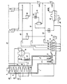
- the drawing is a flow scheme for steam cracking hydrocarbons with generation and distribution of steam at multi-pressure levels by an embodiment of the invention wherein portions of steam at various pressure levels are employed for combustion air preheating.
- pyrolysis furnace 1 having a radiant section 2, convection section 3, and combustion air plenum 4 is heated by fuel burners 5.
- the radiant section contains cracking tubes 6 and convection coils 7, 8, 9, 10, and 11 which are used for feed preheating and steam raising as later described.
- the furnace is equipped with combustion air blower 12 and a combustion air preheater 13 having coils 14 through 17.
- the "hot end" system additionally includes primary quench exchangers 18 which are closely coupled to the cracking tubes for the purpose of rapidly cooling cracked gases below their adiabatic cracking temperature.
- the quench exchangers generate saturated steam from boiler feed water in steam drum 19. Cooled cracked gases from primary quench exchangers 18 are collected in manifold 20 for passage to secondary cooling (not shown).
- Process gas compression and refrigerant compression are significant energy uses in the overall ethylene production process. Shaft work for these compression services is developed by high pressure steam turbines 21 and 22.
- gas oil feed is introduced at 23 to convection coil 9 where it is preheated and then mixed with diluent steam which is introduced at 24 and superheated in convection coil 8.
- the mixed feed is finally heated to incipient cracking temperature in convection coil 11 and introduced to cracking tubes 6.
- combustion air introduced at ambient temperature by blower 12 is successively heated by steam coils 14 through 17 in combustion air preheater 13 to a temperature in plenum 4 of 280°C.
- Combustion gas is then heated by fuel burners 5 to a temperature of 1930°C in the lower part of radiant section 2.
- the combustion gas enters the convection section 3 at a temperature of 1150°C and is further cooled to an exhaust temperature of 150°C by waste heat recovery in the convection section.
- Condensate and boiler feedwater from condensate receiver 25 are introduced at high pressure through line 26 to feedwater heating coil 7 in the upper part of the convection section and then to steam drum 19 which is part of the 105 kg/cm high pressure steam system.
- High pressure saturated steam from drum 19 is superheated to 510°C in convection coil 10 and flows through line 27 for use in two stage turbines 21 and 22.
- Steam from the first stage of turbine 22 is exhausted to upper medium pressure steam header 28 at 42 kg/cm and 400°C and is fed to turbines 29 and 30 for further extraction of shaft work.
- Steam from the first stage of turbine 21 is exhausted to lower medium pressure steam header 31 at 6 kg/cm and 205°C and is fed to dilution steam preheater 32 and other process heating services not shown.
- Steam is exhausted from turbine 29 to low pressure steam header 33 at 1.4 kg/cm and 220°C and then to miscellaneous process heating services indicated generally at 34.
- a portion of the steam from each of the headers 33, 31, and 28 is introduced respectively to coils 14, 15, and 16 in combustion air preheater 13.
- all of the turbine exhaust steam in one or more of these headers may be employed in the air preheater.
- the low temperature coil 14 preheats the cool incoming air and the downstream, successively hotter coils 15 and 16 heat the increasingly warmer air to 210 C.
- the combustion air is finally preheated to a temperature of 280°C by coil 17 which employs saturated steam at 105 kg/cm 2 from steam drum 19.
- Each of the air preheater coils discharges condensate through a pressure letdown system, not shown, to condensate receiver 25.
- the letdown system comprises a flash pot for each coil outlet from which flash steam is discharged to the inlet of the same coil and condensate is reduced in pressure and introduced to the next lower pressure flash pot and, ultimately, flows to the condensate receiver.
Landscapes
- Chemical & Material Sciences (AREA)
- Oil, Petroleum & Natural Gas (AREA)
- Physics & Mathematics (AREA)
- Thermal Sciences (AREA)
- Engineering & Computer Science (AREA)
- Chemical Kinetics & Catalysis (AREA)
- General Chemical & Material Sciences (AREA)
- Organic Chemistry (AREA)
- Production Of Liquid Hydrocarbon Mixture For Refining Petroleum (AREA)
- Engine Equipment That Uses Special Cycles (AREA)
Applications Claiming Priority (2)
| Application Number | Priority Date | Filing Date | Title |
|---|---|---|---|
| US06/812,546 US4617109A (en) | 1985-12-23 | 1985-12-23 | Combustion air preheating |
| US812546 | 1985-12-23 |
Publications (2)
| Publication Number | Publication Date |
|---|---|
| EP0229939A1 true EP0229939A1 (fr) | 1987-07-29 |
| EP0229939B1 EP0229939B1 (fr) | 1988-11-23 |
Family
ID=25209922
Family Applications (1)
| Application Number | Title | Priority Date | Filing Date |
|---|---|---|---|
| EP86116582A Expired EP0229939B1 (fr) | 1985-12-23 | 1986-11-28 | Préchauffage d'air de combustion |
Country Status (11)
| Country | Link |
|---|---|
| US (1) | US4617109A (fr) |
| EP (1) | EP0229939B1 (fr) |
| JP (1) | JPH07116444B2 (fr) |
| KR (1) | KR940011336B1 (fr) |
| CN (1) | CN1009658B (fr) |
| BR (1) | BR8605948A (fr) |
| CA (1) | CA1247655A (fr) |
| DE (1) | DE3661271D1 (fr) |
| MX (1) | MX166054B (fr) |
| NO (1) | NO168486C (fr) |
| YU (1) | YU45372B (fr) |
Cited By (3)
| Publication number | Priority date | Publication date | Assignee | Title |
|---|---|---|---|---|
| EP0365899A3 (fr) * | 1988-10-22 | 1991-06-12 | Linde Aktiengesellschaft | Réacteur pour la mise en oeuvre des procédés de combustion |
| FR2760468A1 (fr) * | 1997-03-05 | 1998-09-11 | Procedes Petroliers Petrochim | Four tubulaire de vapocraquage d'hydrocarbures a double echangeur de trempe |
| US12552996B2 (en) | 2021-03-10 | 2026-02-17 | Linde Gmbh | Method and system for steamcracking |
Families Citing this family (24)
| Publication number | Priority date | Publication date | Assignee | Title |
|---|---|---|---|---|
| JPH0819420B2 (ja) * | 1988-09-05 | 1996-02-28 | 三井石油化学工業株式会社 | 低品位原料の分解処理方法 |
| US5190634A (en) * | 1988-12-02 | 1993-03-02 | Lummus Crest Inc. | Inhibition of coke formation during vaporization of heavy hydrocarbons |
| US5120892A (en) * | 1989-12-22 | 1992-06-09 | Phillips Petroleum Company | Method and apparatus for pyrolytically cracking hydrocarbons |
| ID29093A (id) * | 1998-10-16 | 2001-07-26 | Lanisco Holdings Ltd | Konversi mendalam yang menggabungkan demetalisasi dan konversi minyak mentah, residu atau minyak berat menjadi cairan ringan dengan senyawa-senyawa oksigenat murni atau tak murni |
| FR2796078B1 (fr) * | 1999-07-07 | 2002-06-14 | Bp Chemicals Snc | Procede et dispositif de vapocraquage d'hydrocarbures |
| RU2219218C2 (ru) * | 2001-02-21 | 2003-12-20 | Открытое акционерное общество "Завод Нефтегазмаш" | Трубчатый подогреватель |
| GB0204140D0 (en) * | 2002-02-22 | 2002-04-10 | Bp Chem Int Ltd | Production of olefins |
| US7488459B2 (en) * | 2004-05-21 | 2009-02-10 | Exxonmobil Chemical Patents Inc. | Apparatus and process for controlling temperature of heated feed directed to a flash drum whose overhead provides feed for cracking |
| US20090022635A1 (en) * | 2007-07-20 | 2009-01-22 | Selas Fluid Processing Corporation | High-performance cracker |
| US8815080B2 (en) * | 2009-01-26 | 2014-08-26 | Lummus Technology Inc. | Adiabatic reactor to produce olefins |
| US8277523B2 (en) | 2010-01-05 | 2012-10-02 | General Electric Company | Method and apparatus to transport solids |
| EP2893160B1 (fr) * | 2012-08-03 | 2017-09-27 | Shell Internationale Research Maatschappij B.V. | Procédé pour la récupération d'énergie |
| KR102432485B1 (ko) * | 2016-07-25 | 2022-08-12 | 사빅 글로벌 테크놀러지스 비.브이. | 가스 터빈의 연도 가스를 사용하여 탄화수소 스트림을 분해하는 방법 |
| EP3415587B1 (fr) | 2017-06-16 | 2020-07-29 | Technip France | Système et procédé de four de craquage pour le craquage d'une charge d'hydrocarbures en son sein |
| CN108588678B (zh) * | 2018-05-07 | 2020-06-09 | 西安航空制动科技有限公司 | 一种化学气相沉积炉气体预热装置 |
| HUE063559T2 (hu) * | 2019-06-06 | 2024-01-28 | Technip Energies France | Eljárás egy etilénüzem gõzfejlesztõ körében lévõ gépek meghajtására, valamint integrált etilénüzemi és erõmûvi rendszer |
| EP4056892A1 (fr) | 2021-03-10 | 2022-09-14 | Linde GmbH | Procédé et système de vapocraquage |
| EP4056894A1 (fr) * | 2021-03-10 | 2022-09-14 | Linde GmbH | Procédé et système pour unité de craquage à vapeur |
| EP4056668A1 (fr) | 2021-03-10 | 2022-09-14 | Linde GmbH | Procédé et installation de vapocraquage |
| CN115183223B (zh) * | 2021-04-01 | 2025-05-16 | 中韩(武汉)石油化工有限公司 | 热电联产装置全系统低温余热深度利用的节能方法及系统 |
| US12553669B2 (en) | 2022-03-22 | 2026-02-17 | Lummus Technology Llc | External combustion air preheat |
| US12503411B2 (en) | 2022-08-04 | 2025-12-23 | Kellogg Brown & Root Llc | Low CO2 emission ethane cracker |
| JP2025532505A (ja) | 2022-09-09 | 2025-10-01 | リンデ ゲーエムベーハー | スチームクラッキングのための方法及びシステム |
| WO2025024599A2 (fr) * | 2023-07-24 | 2025-01-30 | Kellogg Brown & Root Llc | Intégration d'unité de vapocraquage et d'unités d'hydrogène bleu pour réduire l'émission de co2 |
Citations (4)
| Publication number | Priority date | Publication date | Assignee | Title |
|---|---|---|---|---|
| FR1538588A (fr) * | 1965-09-01 | 1968-09-06 | Alcorn Comb Co | Procédé et installation pour des réactions chimiques à haute température |
| EP0030446A1 (fr) * | 1979-12-05 | 1981-06-17 | Exxon Research And Engineering Company | Procédé pour le craquage d'hydrocarbures |
| US4479869A (en) * | 1983-12-14 | 1984-10-30 | The M. W. Kellogg Company | Flexible feed pyrolysis process |
| DE3515842A1 (de) * | 1985-05-02 | 1986-11-06 | Linde Ag, 6200 Wiesbaden | Industrieofen sowie verfahren zum betreiben desselben |
Family Cites Families (6)
| Publication number | Priority date | Publication date | Assignee | Title |
|---|---|---|---|---|
| NL128466C (fr) * | 1964-03-07 | |||
| DE1944307A1 (de) * | 1969-09-01 | 1971-03-11 | Metallgesellschaft Ag | Turbinenkraftwerksprozess |
| US3765167A (en) * | 1972-03-06 | 1973-10-16 | Metallgesellschaft Ag | Power plant process |
| US4107226A (en) * | 1977-10-19 | 1978-08-15 | Pullman Incorporated | Method for quenching cracked gases |
| DE3314132A1 (de) * | 1983-04-19 | 1984-10-25 | Linde Ag, 6200 Wiesbaden | Verfahren zum betreiben einer anlage fuer die spaltung von kohlenwasserstoffen |
| JPS6060187A (ja) * | 1983-09-14 | 1985-04-06 | Ishikawajima Harima Heavy Ind Co Ltd | 管式加熱炉の操業方法 |
-
1985
- 1985-12-23 US US06/812,546 patent/US4617109A/en not_active Expired - Lifetime
-
1986
- 1986-09-30 CA CA000519435A patent/CA1247655A/fr not_active Expired
- 1986-10-23 YU YU1802/86A patent/YU45372B/xx unknown
- 1986-10-27 JP JP61255543A patent/JPH07116444B2/ja not_active Expired - Lifetime
- 1986-11-28 EP EP86116582A patent/EP0229939B1/fr not_active Expired
- 1986-11-28 DE DE8686116582T patent/DE3661271D1/de not_active Expired
- 1986-12-04 BR BR8605948A patent/BR8605948A/pt unknown
- 1986-12-12 KR KR1019860010637A patent/KR940011336B1/ko not_active Expired - Fee Related
- 1986-12-17 MX MX0026485A patent/MX166054B/es unknown
- 1986-12-19 CN CN86108633A patent/CN1009658B/zh not_active Expired
- 1986-12-22 NO NO865221A patent/NO168486C/no not_active IP Right Cessation
Patent Citations (4)
| Publication number | Priority date | Publication date | Assignee | Title |
|---|---|---|---|---|
| FR1538588A (fr) * | 1965-09-01 | 1968-09-06 | Alcorn Comb Co | Procédé et installation pour des réactions chimiques à haute température |
| EP0030446A1 (fr) * | 1979-12-05 | 1981-06-17 | Exxon Research And Engineering Company | Procédé pour le craquage d'hydrocarbures |
| US4479869A (en) * | 1983-12-14 | 1984-10-30 | The M. W. Kellogg Company | Flexible feed pyrolysis process |
| DE3515842A1 (de) * | 1985-05-02 | 1986-11-06 | Linde Ag, 6200 Wiesbaden | Industrieofen sowie verfahren zum betreiben desselben |
Cited By (3)
| Publication number | Priority date | Publication date | Assignee | Title |
|---|---|---|---|---|
| EP0365899A3 (fr) * | 1988-10-22 | 1991-06-12 | Linde Aktiengesellschaft | Réacteur pour la mise en oeuvre des procédés de combustion |
| FR2760468A1 (fr) * | 1997-03-05 | 1998-09-11 | Procedes Petroliers Petrochim | Four tubulaire de vapocraquage d'hydrocarbures a double echangeur de trempe |
| US12552996B2 (en) | 2021-03-10 | 2026-02-17 | Linde Gmbh | Method and system for steamcracking |
Also Published As
| Publication number | Publication date |
|---|---|
| CN86108633A (zh) | 1987-07-15 |
| KR870005688A (ko) | 1987-07-06 |
| KR940011336B1 (ko) | 1994-12-05 |
| JPS62148591A (ja) | 1987-07-02 |
| YU45372B (en) | 1992-05-28 |
| US4617109A (en) | 1986-10-14 |
| NO168486C (no) | 1992-02-26 |
| JPH07116444B2 (ja) | 1995-12-13 |
| CN1009658B (zh) | 1990-09-19 |
| NO168486B (no) | 1991-11-18 |
| MX166054B (es) | 1992-12-16 |
| CA1247655A (fr) | 1988-12-28 |
| EP0229939B1 (fr) | 1988-11-23 |
| BR8605948A (pt) | 1987-09-15 |
| DE3661271D1 (en) | 1988-12-29 |
| NO865221L (no) | 1987-06-24 |
| YU180286A (en) | 1988-12-31 |
| NO865221D0 (no) | 1986-12-22 |
Similar Documents
| Publication | Publication Date | Title |
|---|---|---|
| US4617109A (en) | Combustion air preheating | |
| US5327726A (en) | Staged furnaces for firing coal pyrolysis gas and char | |
| KR100385372B1 (ko) | 가스및증기터빈플랜트의운전방법및이에따라동작하는플랜트 | |
| CN1056666C (zh) | 冷却燃气与蒸汽轮机装置的燃气轮机冷却剂的设备 | |
| JP2757290B2 (ja) | 石炭ガス化設備を持ったガス・蒸気タービン複合設備 | |
| JP2024509584A (ja) | スチームクラッキングのための方法及びプラント | |
| NO800484L (no) | Fremgangsmaate og apparat for gjenvinning av varmeenergi i en overladet forbrenningsmotor | |
| US4912282A (en) | Process for operating a plant for the cracking of hydrocarbons | |
| RU2062332C1 (ru) | Комбинированная газопаротурбинная устанвока | |
| US4720968A (en) | Method and apparatus for driving an electrical power plant | |
| CN202595161U (zh) | 高炉炉顶气回收系统 | |
| EP3748138B1 (fr) | Procédé de commande de machines dans un circuit de production de vapeur d'une usine d'éthylène et système intégré d'éthylène et de centrale électrique | |
| KR20230154265A (ko) | 증기 분해 방법 및 시스템 | |
| US2294700A (en) | Elastic fluid power plant | |
| US4637212A (en) | Combined hot air turbine and steam power plant | |
| US4896496A (en) | Single pressure steam bottoming cycle for gas turbines combined cycle | |
| US4287377A (en) | Hydrocarbon conversion | |
| AU674751B2 (en) | Steam turbine | |
| JPH06229207A (ja) | 発電設備の運転方法とそれに基づいて作動する発電設備 | |
| US2617405A (en) | Tubular gas heater, in particular for solid fuels | |
| EP0122806B1 (fr) | Méthode et système pour produire de l'énergie et de la vapeur à basse pression saturée ou presque saturée | |
| RU2715073C1 (ru) | Парогазовая установка с охлаждаемым диффузором | |
| GB2027739A (en) | Hydrocarbon Conversion | |
| EP3628722A1 (fr) | Générateur de gaz de fissure, procédé de production de gaz de fissure | |
| SU969920A1 (ru) | Способ получени дистилл та в регенеративной системе паротурбинной установки |
Legal Events
| Date | Code | Title | Description |
|---|---|---|---|
| PUAI | Public reference made under article 153(3) epc to a published international application that has entered the european phase |
Free format text: ORIGINAL CODE: 0009012 |
|
| AK | Designated contracting states |
Kind code of ref document: A1 Designated state(s): BE DE FR GB IT NL |
|
| 17P | Request for examination filed |
Effective date: 19870827 |
|
| 17Q | First examination report despatched |
Effective date: 19880418 |
|
| GRAA | (expected) grant |
Free format text: ORIGINAL CODE: 0009210 |
|
| AK | Designated contracting states |
Kind code of ref document: B1 Designated state(s): BE DE FR GB IT NL |
|
| ITF | It: translation for a ep patent filed | ||
| REF | Corresponds to: |
Ref document number: 3661271 Country of ref document: DE Date of ref document: 19881229 |
|
| ET | Fr: translation filed | ||
| PLBE | No opposition filed within time limit |
Free format text: ORIGINAL CODE: 0009261 |
|
| STAA | Information on the status of an ep patent application or granted ep patent |
Free format text: STATUS: NO OPPOSITION FILED WITHIN TIME LIMIT |
|
| 26N | No opposition filed | ||
| PGFP | Annual fee paid to national office [announced via postgrant information from national office to epo] |
Ref country code: FR Payment date: 19901018 Year of fee payment: 5 |
|
| ITTA | It: last paid annual fee | ||
| PG25 | Lapsed in a contracting state [announced via postgrant information from national office to epo] |
Ref country code: FR Effective date: 19920731 |
|
| REG | Reference to a national code |
Ref country code: FR Ref legal event code: ST |
|
| PGFP | Annual fee paid to national office [announced via postgrant information from national office to epo] |
Ref country code: NL Payment date: 19990921 Year of fee payment: 14 |
|
| PGFP | Annual fee paid to national office [announced via postgrant information from national office to epo] |
Ref country code: GB Payment date: 19991004 Year of fee payment: 14 |
|
| PGFP | Annual fee paid to national office [announced via postgrant information from national office to epo] |
Ref country code: DE Payment date: 19991125 Year of fee payment: 14 |
|
| PGFP | Annual fee paid to national office [announced via postgrant information from national office to epo] |
Ref country code: BE Payment date: 19991214 Year of fee payment: 14 |
|
| PG25 | Lapsed in a contracting state [announced via postgrant information from national office to epo] |
Ref country code: GB Free format text: LAPSE BECAUSE OF NON-PAYMENT OF DUE FEES Effective date: 20001128 |
|
| PG25 | Lapsed in a contracting state [announced via postgrant information from national office to epo] |
Ref country code: BE Free format text: LAPSE BECAUSE OF NON-PAYMENT OF DUE FEES Effective date: 20001130 |
|
| BERE | Be: lapsed |
Owner name: THE M. W. KELLOGG CY Effective date: 20001130 |
|
| PG25 | Lapsed in a contracting state [announced via postgrant information from national office to epo] |
Ref country code: NL Free format text: LAPSE BECAUSE OF NON-PAYMENT OF DUE FEES Effective date: 20010601 |
|
| GBPC | Gb: european patent ceased through non-payment of renewal fee |
Effective date: 20001128 |
|
| NLV4 | Nl: lapsed or anulled due to non-payment of the annual fee |
Effective date: 20010601 |
|
| PG25 | Lapsed in a contracting state [announced via postgrant information from national office to epo] |
Ref country code: DE Free format text: LAPSE BECAUSE OF NON-PAYMENT OF DUE FEES Effective date: 20010801 |
|
| PG25 | Lapsed in a contracting state [announced via postgrant information from national office to epo] |
Ref country code: IT Free format text: LAPSE BECAUSE OF NON-PAYMENT OF DUE FEES Effective date: 20051128 |