EP0230227A2 - Centrale solaire - Google Patents
Centrale solaire Download PDFInfo
- Publication number
- EP0230227A2 EP0230227A2 EP87100131A EP87100131A EP0230227A2 EP 0230227 A2 EP0230227 A2 EP 0230227A2 EP 87100131 A EP87100131 A EP 87100131A EP 87100131 A EP87100131 A EP 87100131A EP 0230227 A2 EP0230227 A2 EP 0230227A2
- Authority
- EP
- European Patent Office
- Prior art keywords
- solar
- mirror
- collector
- solar system
- supports
- Prior art date
- Legal status (The legal status is an assumption and is not a legal conclusion. Google has not performed a legal analysis and makes no representation as to the accuracy of the status listed.)
- Granted
Links
- 230000005855 radiation Effects 0.000 claims abstract description 49
- 239000006096 absorbing agent Substances 0.000 claims abstract description 38
- 239000002184 metal Substances 0.000 claims description 3
- 229910052751 metal Inorganic materials 0.000 claims description 3
- 125000006850 spacer group Chemical group 0.000 claims description 3
- 239000011888 foil Substances 0.000 claims description 2
- 230000000694 effects Effects 0.000 abstract description 5
- 230000001771 impaired effect Effects 0.000 abstract description 2
- 238000010411 cooking Methods 0.000 description 5
- 239000011521 glass Substances 0.000 description 5
- 229910000831 Steel Inorganic materials 0.000 description 3
- 238000004519 manufacturing process Methods 0.000 description 3
- 239000010959 steel Substances 0.000 description 3
- 238000003860 storage Methods 0.000 description 3
- 230000007704 transition Effects 0.000 description 3
- XLYOFNOQVPJJNP-UHFFFAOYSA-N water Substances O XLYOFNOQVPJJNP-UHFFFAOYSA-N 0.000 description 3
- PXHVJJICTQNCMI-UHFFFAOYSA-N Nickel Chemical compound [Ni] PXHVJJICTQNCMI-UHFFFAOYSA-N 0.000 description 2
- 238000003287 bathing Methods 0.000 description 2
- 238000010276 construction Methods 0.000 description 2
- 230000002349 favourable effect Effects 0.000 description 2
- 239000000463 material Substances 0.000 description 2
- 239000003973 paint Substances 0.000 description 2
- VYZAMTAEIAYCRO-UHFFFAOYSA-N Chromium Chemical compound [Cr] VYZAMTAEIAYCRO-UHFFFAOYSA-N 0.000 description 1
- 230000000295 complement effect Effects 0.000 description 1
- 238000010438 heat treatment Methods 0.000 description 1
- 229910052759 nickel Inorganic materials 0.000 description 1
- 230000000191 radiation effect Effects 0.000 description 1
- 230000002787 reinforcement Effects 0.000 description 1
- 150000003839 salts Chemical class 0.000 description 1
- 230000001932 seasonal effect Effects 0.000 description 1
- 230000009182 swimming Effects 0.000 description 1
- 239000008399 tap water Substances 0.000 description 1
- 235000020679 tap water Nutrition 0.000 description 1
- 239000002023 wood Substances 0.000 description 1
Images





Classifications
-
- H—ELECTRICITY
- H02—GENERATION; CONVERSION OR DISTRIBUTION OF ELECTRIC POWER
- H02S—GENERATION OF ELECTRIC POWER BY CONVERSION OF INFRARED RADIATION, VISIBLE LIGHT OR ULTRAVIOLET LIGHT, e.g. USING PHOTOVOLTAIC [PV] MODULES
- H02S40/00—Components or accessories in combination with PV modules, not provided for in groups H02S10/00 - H02S30/00
- H02S40/20—Optical components
- H02S40/22—Light-reflecting or light-concentrating means
-
- F—MECHANICAL ENGINEERING; LIGHTING; HEATING; WEAPONS; BLASTING
- F24—HEATING; RANGES; VENTILATING
- F24S—SOLAR HEAT COLLECTORS; SOLAR HEAT SYSTEMS
- F24S20/00—Solar heat collectors specially adapted for particular uses or environments
- F24S20/30—Solar heat collectors for heating objects, e.g. solar cookers or solar furnaces
-
- F—MECHANICAL ENGINEERING; LIGHTING; HEATING; WEAPONS; BLASTING
- F24—HEATING; RANGES; VENTILATING
- F24S—SOLAR HEAT COLLECTORS; SOLAR HEAT SYSTEMS
- F24S20/00—Solar heat collectors specially adapted for particular uses or environments
- F24S20/50—Rollable or foldable solar heat collector modules
-
- F—MECHANICAL ENGINEERING; LIGHTING; HEATING; WEAPONS; BLASTING
- F24—HEATING; RANGES; VENTILATING
- F24S—SOLAR HEAT COLLECTORS; SOLAR HEAT SYSTEMS
- F24S23/00—Arrangements for concentrating solar-rays for solar heat collectors
- F24S23/70—Arrangements for concentrating solar-rays for solar heat collectors with reflectors
- F24S23/77—Arrangements for concentrating solar-rays for solar heat collectors with reflectors with flat reflective plates
-
- F—MECHANICAL ENGINEERING; LIGHTING; HEATING; WEAPONS; BLASTING
- F24—HEATING; RANGES; VENTILATING
- F24S—SOLAR HEAT COLLECTORS; SOLAR HEAT SYSTEMS
- F24S25/00—Arrangement of stationary mountings or supports for solar heat collector modules
- F24S25/10—Arrangement of stationary mountings or supports for solar heat collector modules extending in directions away from a supporting surface
-
- F—MECHANICAL ENGINEERING; LIGHTING; HEATING; WEAPONS; BLASTING
- F24—HEATING; RANGES; VENTILATING
- F24S—SOLAR HEAT COLLECTORS; SOLAR HEAT SYSTEMS
- F24S25/00—Arrangement of stationary mountings or supports for solar heat collector modules
- F24S25/70—Arrangement of stationary mountings or supports for solar heat collector modules with means for adjusting the final position or orientation of supporting elements in relation to each other or to a mounting surface; with means for compensating mounting tolerances
-
- F—MECHANICAL ENGINEERING; LIGHTING; HEATING; WEAPONS; BLASTING
- F24—HEATING; RANGES; VENTILATING
- F24S—SOLAR HEAT COLLECTORS; SOLAR HEAT SYSTEMS
- F24S60/00—Arrangements for storing heat collected by solar heat collectors
-
- F—MECHANICAL ENGINEERING; LIGHTING; HEATING; WEAPONS; BLASTING
- F24—HEATING; RANGES; VENTILATING
- F24S—SOLAR HEAT COLLECTORS; SOLAR HEAT SYSTEMS
- F24S60/00—Arrangements for storing heat collected by solar heat collectors
- F24S60/30—Arrangements for storing heat collected by solar heat collectors storing heat in liquids
-
- Y—GENERAL TAGGING OF NEW TECHNOLOGICAL DEVELOPMENTS; GENERAL TAGGING OF CROSS-SECTIONAL TECHNOLOGIES SPANNING OVER SEVERAL SECTIONS OF THE IPC; TECHNICAL SUBJECTS COVERED BY FORMER USPC CROSS-REFERENCE ART COLLECTIONS [XRACs] AND DIGESTS
- Y02—TECHNOLOGIES OR APPLICATIONS FOR MITIGATION OR ADAPTATION AGAINST CLIMATE CHANGE
- Y02B—CLIMATE CHANGE MITIGATION TECHNOLOGIES RELATED TO BUILDINGS, e.g. HOUSING, HOUSE APPLIANCES OR RELATED END-USER APPLICATIONS
- Y02B10/00—Integration of renewable energy sources in buildings
- Y02B10/10—Photovoltaic [PV]
-
- Y—GENERAL TAGGING OF NEW TECHNOLOGICAL DEVELOPMENTS; GENERAL TAGGING OF CROSS-SECTIONAL TECHNOLOGIES SPANNING OVER SEVERAL SECTIONS OF THE IPC; TECHNICAL SUBJECTS COVERED BY FORMER USPC CROSS-REFERENCE ART COLLECTIONS [XRACs] AND DIGESTS
- Y02—TECHNOLOGIES OR APPLICATIONS FOR MITIGATION OR ADAPTATION AGAINST CLIMATE CHANGE
- Y02B—CLIMATE CHANGE MITIGATION TECHNOLOGIES RELATED TO BUILDINGS, e.g. HOUSING, HOUSE APPLIANCES OR RELATED END-USER APPLICATIONS
- Y02B10/00—Integration of renewable energy sources in buildings
- Y02B10/20—Solar thermal
-
- Y—GENERAL TAGGING OF NEW TECHNOLOGICAL DEVELOPMENTS; GENERAL TAGGING OF CROSS-SECTIONAL TECHNOLOGIES SPANNING OVER SEVERAL SECTIONS OF THE IPC; TECHNICAL SUBJECTS COVERED BY FORMER USPC CROSS-REFERENCE ART COLLECTIONS [XRACs] AND DIGESTS
- Y02—TECHNOLOGIES OR APPLICATIONS FOR MITIGATION OR ADAPTATION AGAINST CLIMATE CHANGE
- Y02E—REDUCTION OF GREENHOUSE GAS [GHG] EMISSIONS, RELATED TO ENERGY GENERATION, TRANSMISSION OR DISTRIBUTION
- Y02E10/00—Energy generation through renewable energy sources
- Y02E10/40—Solar thermal energy, e.g. solar towers
- Y02E10/47—Mountings or tracking
-
- Y—GENERAL TAGGING OF NEW TECHNOLOGICAL DEVELOPMENTS; GENERAL TAGGING OF CROSS-SECTIONAL TECHNOLOGIES SPANNING OVER SEVERAL SECTIONS OF THE IPC; TECHNICAL SUBJECTS COVERED BY FORMER USPC CROSS-REFERENCE ART COLLECTIONS [XRACs] AND DIGESTS
- Y02—TECHNOLOGIES OR APPLICATIONS FOR MITIGATION OR ADAPTATION AGAINST CLIMATE CHANGE
- Y02E—REDUCTION OF GREENHOUSE GAS [GHG] EMISSIONS, RELATED TO ENERGY GENERATION, TRANSMISSION OR DISTRIBUTION
- Y02E10/00—Energy generation through renewable energy sources
- Y02E10/50—Photovoltaic [PV] energy
- Y02E10/52—PV systems with concentrators
Definitions
- the invention relates to a solar system with flat absorbers and / or solar cells in a collector field, at the edges of which at least partially one or more flat mirror surfaces are arranged at an angle to the absorbers and / or solar cells, the solar radiation impinging on the mirror surfaces at least partially falls on the absorbers and / or solar cells.
- Such a solar system is already known, in which the mirrors are formed by rollable mirror films which can be pivoted so that there is a certain uniaxial sun tracking of the rollable mirror films.
- the tracking of the mirror film requires considerable effort and heavy wear, so that the mirror film has to be replaced more often.
- the mirror surfaces are only arranged on the north edge of the absorber surface (US Pat. No. 4,316,448).
- the mirror surfaces are only pivotally attached to the south edge of the absorber.
- the swiveling is not used for sun tracking, but at night the mirror is swiveled over the absorber surface to protect it from rain, snow, hail and the like.
- This system also shows, like the one already mentioned, the disadvantage that the mirrors are not effective early in the morning and late at night, because the mirror surfaces have only the width of the absorber surfaces (JP -OS 58/213 158).
- a salt heat store with rigid mirrors is also known, which has an end wall in the east and west, which can consist of mirror foils.
- This is very expensive and must be held in place by numerous reinforcements that cast shadows on the water surface to be heated (US Pat. No. 4,326,498).
- Another solar collector can track the sun biaxially, which compensates for the disadvantage that the opening angle between the mirror surfaces is relatively very small.
- the cost of two-axis trackable systems is very high, and such systems are also prone to wear and failure (DE-OS 25 23 479).
- DE-OS 25 23 479 the same applies to another system which is arranged on the roof of a building and has a pivoting mirror on the south edge.
- a two-axis sun tracking is not provided here, so that due to the relatively small opening angle, this system practically only works around noon (US Pat. No. 3,841,302).
- the invention has for its object to equip a solar system with mirrors and absorber surfaces and / or solar cells, in which not only the directly incident solar radiation is used, but also the early morning and late sun rays without providing any sun tracking of the mirrors or the absorber surfaces is.
- the floor or roof area requirement should be as low as possible.
- the mirror surfaces and the absorber and / or solar cell cells are arranged rigidly on the roof of a building or on supporting elements, that the mirror surfaces extend in a plane extending to the north and / or south and inclined to the absorber plane are attached, and that the mirror surfaces extend laterally beyond the absorber surfaces with respect to the absorbers without shading.
- Fig. 1 shows an industrial solar system, which serves to raise the temperature of the return water of the return line of a district heating network in this city.
- 1,000 square meters of vacuum collectors 2 are arranged on the supports 4,5, 6, 7 and 8 at a distance above the ground in a single horizontal plane next to and one behind the other on double-track railroad tracks.
- the subject of the invention now shows, for example, a board wall 3 above the north support 8, which is held in position by supports 9, 10, 11 and secured against storm.
- the south side of the plank wall 3 is provided with a mirror surface 1, which can be a mirror film or a reflective metal sheet such as a rust-free chrome nickel sheet.
- the mirror surface 1 it is also possible for the mirror surface 1 to be formed by industrial mirror glass, which, however, is the most complex solution.
- mirror glass does not even cause 1/10 of the cost of vacuum tube collectors per square meter.
- the angle ⁇ between the collector array 2 and the mirror surface 1 is chosen equal to 90 ° here.
- the maximum radiation at noon in our latitudes is around 60 ° at noon on June 21. Only the center beam is shown, the person skilled in the art can understand that the radiation arrives over the entire mirror surface 1.
- the angle of incidence in relation to the flat surface is equal to the angle of reflection.
- the highest 60 ° center beam is thrown onto collector field 2, if only on the right part thereof, like the 10 ° beam, which is also shown.
- FIG. 2 shows the top view on a greatly reduced scale of the embodiment according to FIG. 1. It can be seen that the north wall with the support element 3 and the mirror surface 1 on the collector field 2 is extended to the west to the left and east to the right beyond the edge of the collector field 2. This makes it possible to also deflect the radiation of 10 ° or 30 °, for example 10 ° or 30 °, as shown, onto the collector field 2.
- the collector array 2 according to FIG. 1 is also underlaid with a mirror surface 29 a. As a result, the solar radiation passing between the collector strips in the tubes is reflected by the mirror surface 29a and then strikes the collector strips.
- FIGS. 1 and 2 shows no additional floor space requirement. Only for the supports 9, 10 and 11 and possible further supports, a small area requirement on the floor is required, as can be seen in FIG. 1.
- Fig. 3 shows the schematic side view of a small system.
- a collector 2 is shown schematically, which can also be integrated in the roof 21 in a known manner.
- the mirror surface 1 with the support element 3 is again arranged at an angle ⁇ to the collector 2.
- the support element 3 is held by the horizontally lying support 12 and further parallel supports.
- an additional mirror surface 17 with the support element 3a is now arranged approximately horizontally at an angle ⁇ 1 to the roof 21, which is held by the support 18 and possible further parallel supports.
- ⁇ 1 the very low sun rays of 10 ° and less, which strike at point 25, can be deflected onto the collector 2.
- the high solar radiation above point 25 of mirror surface 17 no longer reaches collector 2 here, at most about 35 ° solar radiation will still reach collector 2 via mirror surface 17.
- the two mirror surfaces 1 and 17 complement each other.
- the mirror surface 17 is more suitable for the low, the mirror surface 1 for the high solar radiation.
- Fig. 4 shows the schematic side view of a small thermal siphon system, which is arranged on the flat roof of a building.
- the collector 2 is arranged here at an angle of inclination of approximately 45 ° through a frame with the supports 13, 14.
- the storage container 16 which is partly held on the same and partly on additional supports 15, as is shown in the prior art. Therefore, this need not be explained further.
- FIG. 3 here again two mirror surfaces 1, 17 are arranged at an angle ⁇ on the northern upper edge and an angle ⁇ on the southern lower edge of the collector 2. While the angle ⁇ is chosen to be approximately as large as in FIG. 3, the angle ⁇ has now been chosen to be smaller, specifically because of the support 18 at the southern end of the mirror surface 17, this is approximately at an angle of 15 ° to the horizontal flat roof. In this way, the 45 ° radiation, as shown, can be deflected onto the collector 2 by the mirror surface 17. With regard to the mirror surface 1, the conditions are the same as in FIG. 3.
- hinges 19, 20 are arranged between the mirror surface with the support element 3a and the collector 2 and between the latter and the mirror surface 1 with the support element 3.
- the angle ⁇ can be set larger and the angle ⁇ smaller than shown by adjusting the supports 12 and removing the support 8 entirely.
- the specialist for this summer-winter setting will provide locks for the support elements 3 and 3a through the supports 12 and 18 so that the system can also withstand the possible stresses caused by a strong storm.
- this applies particularly to the upper support element 3 with the mirror surface 1.
- this is less endangered by north winds because the store partially provides slipstream.
- the east and west winds are also harmless because they hit the narrow surfaces of the system. Only the south winds have to be absorbed by the supports.
- the supports 12 are also able to absorb the wind load of the south winds there, especially since the roof 21 causes a wind blockage.
- the invention shows the advantage that it can be retrofitted to all known solar systems.
- it is preferred to install the conventional part of the system first, whereupon the support elements are attached with the mirror surfaces. These can be prefabricated, but the manufacture is very simple, so that they can also be done by hand. Due to the close proximity of the mirrors to the collectors, this does not have to be precision work.
- the angle ⁇ can be chosen differently, because these rays are known to always be low.
- the angle ⁇ can also be chosen to be equal to 0 as in FIG. 4.
- FIGS. 1 and 2 there are large systems that are built very differently than that shown in FIGS. 1 and 2.
- closed long rows of solar modules were placed on supports on the German North Sea island of Pellworm.
- a large number of further rows are arranged at a distance from the sun.
- the known arrangement is not favorable because it cannot be prevented that the solar modules shade each other, particularly in winter and in the transition periods, but also in the morning and in the evening. This cannot be completely prevented even by very large distances between the individual rows.
- the known arrangement of the collectors vertically at a greater distance above one another has the advantage that the collectors can never shade each other.
- the top mirror surfaces 1 with the support elements 3 at an angle slightly larger than 60 ° to the horizontal according to FIGS. 3 and 4 very conveniently on each collector. Only the lower mirror surface 17 with the support element 3a can only be arranged on the lowest row of modules.
- the invention has the surprising effect that a significant increase in performance can be produced with very little effort because the frame is already present.
- the struts for the collectors or solar modules which are present anyway, can be used to attach the support elements 3. If there is no direct sunlight, i.e. in cloudy weather, the collectors continue to work in the known manner. In addition, a part of the scattered radiation is deflected in the desired manner, in particular by the approximately horizontally lying mirror surfaces 17.
- Fig. 5 shows an embodiment which is arranged on a flat roof 39 or the like horizontal surface area.
- only one floor bar 37 is visible.
- FIG. 6 shows, this and numerous other parts are provided twice, which lie exactly behind them and are therefore not visible in this side view.
- the left is south and the right is north.
- the bottom bar 37 shows a number of holes 32, 33, 34, 35 at its northern end, a bolt being inserted into the southernmost hole 32 to secure the upper rocker 12, which follows extends to the left.
- the dash-dotted lines show the vacuum tube collectors of the collector array 2, which lie behind the bottom bar 37, as can also be seen in FIG. 6.
- the bolt 19 fastened by the bolt 19, is the southern support element 3a, on which the mirror surface 17 is fastened.
- a support 18 which can be folded down after lifting the support element 3 a.
- the rocker 31 is arranged at an angle ⁇ to the bottom bar 37, which in this case is 40 °. This is the winter setting for around the months of November, December and January.
- the position of the south mirror 17 above that shown must also be changed, because otherwise the radiation would no longer be thrown onto the collector field 2 via the mirror 17 at a larger angle ⁇ .
- the bolt 19 is loosened and the southern edge of the support element 2 a is raised and the support 18 is placed vertically downwards. This can also be done in several positions, so that the mirror surface 17 reaches different angles.
- Fig. 6 shows the top view.
- the support elements 3, 3a extend far beyond the collector field 2 to the east and west, so that the solar radiation is also reflected on the collector field 2 early in the morning and late at night, which is indicated here by broken lines.
- These are vacuum tube collectors, for which the horizontal arrangement as shown in FIG. 1 is preferred today. It is also known to arrange mirror channels under the collectors in order to reflect the radiation coming from above into the tubes and onto the absorber surfaces in the tubes. Among other things, this is necessary in order to use the solar radiation reflected on the glass tubes as completely as possible.
- the absorber surfaces within the tubes are arranged inclined at a certain angle to the horizontal, as is known to the person skilled in the art.
- the subject of the invention can also be made from a wide variety of materials.
- a wooden construction is shown, however, with all rods and wings as well as the supporting elements 3, 3a being made of wood, because this is a relatively cheap material. But there is also the possibility to do this from metal and plastic.
- the two floor poles 37, 37a are formed in one piece to the left, as to the south, up to the end of the mirror surface 17. However, there is also the possibility that the floor poles are made shorter, they actually only need to reach as far as the bolt 20. The above-mentioned implementation took place only for greater stability.
- the embodiment according to FIGS. 5 and 6 has the advantage that it is easily accessible and can be easily arranged on flat roofs. It is not necessary to change the flat roof in any way on a flat roof. If a fastening for receiving the wind load appears to be necessary, three ropes can be run from the mirror holder to the ends of the flat roof, which are led down there to the flat roof and fastened or braced on the masonry. This ensures that the flat roof cannot be damaged and does not have to be attacked.
- sun rays lower than 30 °, as shown in FIG. 5, are reflected to the collector array 2 in the same way. Therefore, the invention according to FIGS. 5 and 6 is particularly well suited for winter operation. According to FIG. 5, the lower the sun's rays, the greater the use of the incoming radiation by the mirror. Therefore, the innovation object is particularly suitable for winter use even without the support element 3a and the mirror 17. This means that the supports 18, 18a can of course also be omitted.
- this embodiment shows the advantage that no snow or hailstorm on the mirror surface 1 and. can also not reach collector field 2. In any case, the collector field 2 is also protected in this way in the dimensions shown.
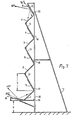
- FIG. 7 shows a vertical mast 10 which is connected to the vertical mast 10 by an oblique northern mast 11 with one or more horizontal crossbars, not shown.
- this vertical mast several horizontal beams 16, 17, 18, 19, 20 are attached from the bottom to the top on the south side. 7 is south on the left and north on the right.
- leading supports 12, 13, 14, 15 are attached at an angle of 60 ° upward to the left, furthermore intermediate solar collectors 1, 2, 3, 4, which in this case are at an angle of 45 ° are arranged to the horizontal.
- the lower edge of the lowermost collector 1 is at a distance a from the floor.
- the distance to and between the other collectors 2-4 is kept so large that substantial mutual shading of the collectors is not possible throughout the year. This is because in our latitudes the maximum solar radiation is about 60 °.
- Identical masts are arranged behind the mast 10 at certain intervals of, for example, 3 m, which are connected to one another by the horizontal cross members 16-20 mentioned.
- the inclined supports 11 can also be reproduced accordingly. They only serve to record the wind load when necessary, i.e. that is, they can also be omitted if the vertical masts 10 are designed accordingly, for example as known lattice masts made of steel. Shown. is an arrangement of wooden poles, which are connected by a few rustproof bolts in corresponding holes.
- the system according to FIG. 7 essentially belongs to the prior art.
- the struts 12-15 were arranged horizontally in accordance with the prior art; according to the innovation, they are at an angle of 60 ° to the horizontal.
- planar support elements with reflecting surfaces which are to be referred to here as "mirrors", 5, 6, 7, 8 are now also arranged on the upper edge of the collectors 1, 2, 3, 4 in that they are attached to the struts 12 -15 are attached. Between these struts and the lower edge of the collectors, further horizontal supports, not shown but shown, can be provided. These lie parallel to the horizontal beams 16-20 mentioned.
- the mode of operation for the rest is shown below and above.
- the 20 ° and the 45 ° beam are shown below. This strikes the mirror 9 and is deflected by this onto the collector 1.
- the center beam was selected here. The person skilled in the art will understand that the radiation is incident overall, the center vector is only used to represent the total radiation.
- the mode of operation of the mirrors 5-8 attached to the upper edge is shown in the uppermost region of FIG. 1.
- the 10 ° and 50 ° radiation can be seen. This makes it clear that the intervening radiation is deflected to the lower collectors throughout the day even if they come strongly from the east or west, south-east or south-west, early in the morning or late at night.
- the angle of inclination could also be chosen to be zero. To do this, only struts 12-15 would have to be extended. This would have the advantage that the wind load would be lower, because a larger space would arise between the mirrors and the lower edge of the collectors, which is not occupied by the southern and northern winds.
- FIG. 7 The embodiment according to FIG. 7 is generally used on the floor in large systems. However, there is also the option of installing them on any roofs of buildings, even in the middle of large cities. The distance a could then be omitted.
- collector stand 15 for holding the collector field 2 of a conventional type.
- collector stands mostly consist of tubular steel and are provided with feet 48 for placement on the floor or flat roof. This need not be described in detail because it is known to the person skilled in the art.
- the angle of inclination here is 45 °.
- the subject of the invention now shows a frame which also rests on feet 45, 46 and 55. In truth, there are of course several feet behind it.
- the frame with the horizontal floor bars 37, 37a is, as can also be seen in FIG. 9, built around the conventional collector stand 15. It is thus possible to additionally mount the frame with collectors 2 when the collector stand 15 is already installed.
- a support element 3b is fastened with a reflecting surface 1a, preferably also screwed on.
- the mode of operation is again shown by the 50 ° beam on the left, which strikes the center 25 of the mirror surface 17 and is directed correctly onto the collector surface 2.
- the 50 ° beam strikes the mirror surface 1a at point 22 and is also deflected from there onto the collector 2. The same applies to the 10 ° beam, which also hits point 22.
- the ropes 49 are shown left and 54 right, through which the system against the wind load with the flat roof 29 are braced.
- the cable 49 leads around the upper edge of the flat roof 29 and is fastened there to a hook 56 which has been doweled into the horizontal wall of the building.
- the other ropes 53, 54 see Fig. 9, are braced with the house or the ground.
- Fig. 9 shows on the left that there are 2 ropes 49, 50 at a distance from each other.
- Fig. 9 there is again south on the left and north on the right, while west is at the top and east at the bottom. It can be seen that the mirror surfaces 17 and 1 a are extended with the support element 3 b to the east and west in a straight line far beyond the collector field 2. As a result, the eastern and western radiations can also be directed onto the collector 2, as already mentioned above.
- the collector field 2 can again be tube collectors, which is indicated by the lines running from south to north.
- the back of the support element 3 b which in this case can and should serve as a kind of roof surface. It can clearly be seen that this largely covers the collector field 2. This will protect the collector from snow and hail, so that it can also be effective in winter. In winter, however, the frame is adjusted so that the angle of inclination ⁇ to the floor is changed significantly, for example by using the last hole 35 in the floor bar 37, 37a. This is preferably dimensioned such that the angle ⁇ is then only 40 °. In this way, the collector 2 is then completely covered in winter so that it can be fully effective even after heavy snowfall without the need to remove the snow.
- a spacer rod 38 is arranged between the two bottom rods at the left end.
- the screws for fastening the support element 3b to the rods 40, 40a are not shown; the fastening can also be carried out in other ways, for example by nailing.
- the mirror surfaces 17, 1a need not be glass mirrors. Rather, any reflective surface can be used.
- it can be white paint, which also has specular properties, reflecting both diffuse or scattered radiation and direct sunlight.
- white paint has the advantage that the effort is very low, even more than the use of mirror film.
- the embodiment according to FIG. 7 can also be attached to the south facade of a building.
- the masts 11 and possibly also the masts 10 can be omitted, as can the horizontal beams 16-20.
- the collectors 1-4 and the struts 12-15 are then attached directly and in a known manner to the south facade of the building. This is the Understandable by a person skilled in the art, without it being shown in the drawing.
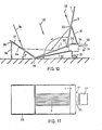
- Fig. 10 you can see below the frame 32 of a solar cooker, which is used on the right to accommodate the two wheels 31. Another wheel is arranged on the frame 32 exactly behind the wheel 31 shown. About these wheels you can see the memory 30, which is encased in a heat-insulating shell.
- a tube collector 2 is arranged on the left, while the opened cover 33 connects on the right, which is connected to the housing by the hinge 34 at the top, while a stop 39 is provided at the bottom.
- the hotplate 35 can be seen above the heat accumulator 30.
- the mirror surfaces 1, 17 are now provided on the supporting elements 3, 3a and are connected to the collector housing or frame 32 via the hinges 19, 20. This allows the mirror surfaces to be adjusted in their angle or ⁇ to the horizontal.
- a support 18 is visible on the left at the left end of the support element 3a, which is movable relative to the support element 3a via a hinge 36. This makes it easy to adjust the angle ⁇ . It is only necessary to set the support 18, which is shown exactly vertically here, obliquely outwards, whereupon the angle ⁇ becomes smaller.
- a hinge 20 which is arranged so that the support element can be folded down completely on the collector 2 for the purpose of transport.
- the support element 3 a can also be rotated by turning to the right in FIG. 10 about the hinge 19 on the collector 2. This will make it Entire device prepared for transport in a very space-saving manner.
- the support 12 is visible on the right. This can also be adjusted to change the angle ⁇ relative to the horizontal.
- arrows 36, 37 and 38 are shown at a distance from one another, which are intended to represent the solar radiation at an angle of approximately 70 °.
- 36 is the center beam that strikes the mirror surface 17 and is intended to represent the total radiation on this surface.
- the radiation 37 strikes the collector directly, which would also be the case without the mirrors.
- the radiation according to arrow 38 hits point 22 of mirror surface 1 in the middle and is also deflected downwards onto collector 2 from there. Since the mirror surface 1 is significantly larger than the collector surface 2, an overall increase in output of over 100% can be recorded in this case compared to the effectiveness of the collector 2 without the mirror surfaces 1 and 17. This is of course particularly important in industrialized countries who are less exposed to the sun than in some developing countries. On the other hand, there is also the possibility, particularly in developing countries, of making the collector 2 significantly smaller if the mirror arrangement is present.
- mirror surfaces are much cheaper than collector surfaces. It does not have to be a glass mirror, but the use of mirror films and other reflecting surfaces is also possible.
- the collector 2 is a tube collector. It can also be seen on the right that the support 12 is arranged behind the hotplate 35 at the upper edge of the heat accumulator with respect to FIG. 10, so that the cooking person can stand at the rear edge according to FIG. 11 without the support 12 preventing it.
- the inner surface of the lid 33 is designed as a support surface, which lies approximately in the same plane as the hotplate 35. As a result, the cooking person has a support surface at the same time.
- the support element 3 When cooking during the day, the support element 3 also has the advantage that the cooking person is in the shade. If cooking takes place in the evening, the support elements 3, 3a can also be folded in, since they are then not required.
- angles ⁇ and ⁇ are changed according to the requirements. In the transition periods and further away from the equator, these angles are chosen smaller. Here, ⁇ can be significantly smaller than 90 °. At the equator, however, ⁇ is chosen to be greater than 90 °, as shown, so that the midday solar radiation is also deflected. Of course it is possible to make this adjustment several times a day depending on the time of day. However, this is not necessary. You can also work with a certain optimal setting of the two angles throughout the day, in which case it is accepted that one or the other mirror surface is only partially effective.
- the frame is formed here similarly as before by the vertical supports 10, 12a and d supports 11 which extend obliquely to the floor. Above the supports are connected to one another by struts 60, which are horizontally connected by horizontal cross beams 17, 18, as before. In this case, a collector 1 c is arranged above it, which is simultaneously formed in a known manner as a heat store.
- the inclined supports 11 are extended in a straight line above the connection of the supports 12 a to the cross member 18 to accommodate the mirrors 6. These are thus arranged on the northern edge of the collector array 1 c at an angle of, for example, 70 ° to the floor. As a result, the mode of operation is as described above and therefore does not have to be shown again. Likewise, the mirrors 6, together with their pick-up elements, which are not shown separately here, are extended to the east and west beyond the collector field 1c, as described above.
- the storage collector 1 c is connected to the shower 68. It is therefore an outdoor shower that can be used for example in outdoor pools, but also on bathing beaches. Such outdoor pool showers are known in principle to the person skilled in the art, so that this need not be shown in detail.
- the invention heats the shower water solar because it is usually tap water that is too cold for showering.
- the supports and the crossbeams can consist of relatively thin, rust-protected steel pipes.
- FIG. 13 shows an embodiment in which the supports 11 are oriented obliquely to the south, on which the mirrors 5, 6 together with their support elements (not shown separately) are arranged approximately vertically, to which the collectors or solar modules 1 c, 2 and 3 Connect in the manner shown.
- the uppermost mirror 4a is arranged in this case on the uppermost extension of the vertical support 10.
- the two supports 10 and 11 are connected to one another by cross supports 60, 61.
- This construction is used in particular in the vicinity of the equator, where the mirrors 4a, 5 and 6 are arranged, for example, at an angle of 90 °, while the collectors or solar modules 1 c, 2 and 3 are at a relatively small angle, for example 25 ° are arranged to the horizontal, for example when the system is erected on the 25th parallel.
- the mirrors are extended to the east and west along with their supporting elements beyond the collectors, as before.
Landscapes
- Engineering & Computer Science (AREA)
- Mechanical Engineering (AREA)
- General Engineering & Computer Science (AREA)
- Sustainable Development (AREA)
- Sustainable Energy (AREA)
- Thermal Sciences (AREA)
- Chemical & Material Sciences (AREA)
- Combustion & Propulsion (AREA)
- Physics & Mathematics (AREA)
- Life Sciences & Earth Sciences (AREA)
- Saccharide Compounds (AREA)
- Organic Low-Molecular-Weight Compounds And Preparation Thereof (AREA)
- Agricultural Chemicals And Associated Chemicals (AREA)
- Optical Elements Other Than Lenses (AREA)
- Road Signs Or Road Markings (AREA)
- Liquid Crystal (AREA)
- Window Of Vehicle (AREA)
- Ship Loading And Unloading (AREA)
- Photovoltaic Devices (AREA)
Priority Applications (1)
| Application Number | Priority Date | Filing Date | Title |
|---|---|---|---|
| AT87100131T ATE60884T1 (de) | 1986-01-15 | 1987-01-08 | Solaranlage. |
Applications Claiming Priority (8)
| Application Number | Priority Date | Filing Date | Title |
|---|---|---|---|
| DE3600881A DE3600881C1 (en) | 1986-01-15 | 1986-01-15 | Solar installation |
| DE3600881 | 1986-01-15 | ||
| DE8603227U | 1986-02-07 | ||
| DE8603227U DE8603227U1 (de) | 1986-02-07 | 1986-02-07 | Spiegelhalter für Solaranlagen |
| DE8609268U | 1986-04-05 | ||
| DE8609268U DE8609268U1 (de) | 1986-04-05 | 1986-04-05 | Solarkraftwerk |
| DE8613478U DE8613478U1 (de) | 1986-05-17 | 1986-05-17 | Solarherd |
| DE8613478U | 1986-05-17 |
Publications (3)
| Publication Number | Publication Date |
|---|---|
| EP0230227A2 true EP0230227A2 (fr) | 1987-07-29 |
| EP0230227A3 EP0230227A3 (en) | 1988-01-27 |
| EP0230227B1 EP0230227B1 (fr) | 1991-02-13 |
Family
ID=27433506
Family Applications (1)
| Application Number | Title | Priority Date | Filing Date |
|---|---|---|---|
| EP87100131A Expired - Lifetime EP0230227B1 (fr) | 1986-01-15 | 1987-01-08 | Centrale solaire |
Country Status (5)
| Country | Link |
|---|---|
| EP (1) | EP0230227B1 (fr) |
| AT (1) | ATE60884T1 (fr) |
| DE (1) | DE3768014D1 (fr) |
| ES (1) | ES2021611B3 (fr) |
| GR (1) | GR3001938T3 (fr) |
Cited By (7)
| Publication number | Priority date | Publication date | Assignee | Title |
|---|---|---|---|---|
| DE3840895A1 (de) * | 1988-02-23 | 1989-10-05 | Wenzel Joachim | Solaranlage |
| US4933020A (en) * | 1987-06-06 | 1990-06-12 | Joachim Wenzel | Solar installation |
| RU2183002C2 (ru) * | 2000-04-12 | 2002-05-27 | Открытое акционерное общество "Ракетно-космическая корпорация "Энергия" имени С.П. Королева" | Концентрирующее устройство |
| WO2010079250A1 (fr) * | 2009-01-12 | 2010-07-15 | Universidad Politécnica de Madrid | Système de panneaux solaires mobiles pour la construction |
| DE102009033771A1 (de) * | 2009-07-17 | 2011-04-07 | Schünemann, Gerhard | Solarreflektor zur Leistungssteigerung von Photovoltaikanlagen und Verwendung eines solchen Solarreflektors |
| DE102015007792A1 (de) | 2015-06-19 | 2016-12-22 | Klaus Scholl | Reflektor für Solarmodule |
| US10505492B2 (en) | 2016-02-12 | 2019-12-10 | Solarcity Corporation | Building integrated photovoltaic roofing assemblies and associated systems and methods |
Families Citing this family (1)
| Publication number | Priority date | Publication date | Assignee | Title |
|---|---|---|---|---|
| ES2288084B1 (es) * | 2005-07-29 | 2008-12-16 | Marcelino E. Ramirez Silva | Metodo para aumentar la produccion de energia electrica y termica de las placas solares. |
Family Cites Families (11)
| Publication number | Priority date | Publication date | Assignee | Title |
|---|---|---|---|---|
| US3025851A (en) * | 1958-06-19 | 1962-03-20 | Hyman A Steinberg | Solar oven |
| US3841302A (en) * | 1974-02-06 | 1974-10-15 | Wormser Scient Corp | Solar energy system for a building |
| DE2523479A1 (de) * | 1975-05-23 | 1976-12-09 | Peter Dr Ing Marx | Solar-kollektor |
| CH600262A5 (en) * | 1975-11-28 | 1978-06-15 | Elias Benoudiz | Multielement solar energy fluid heater |
| DE2557843A1 (de) * | 1975-12-22 | 1977-06-30 | Theo Lenz | Feststehender sonnenkollektor mit integriertem reflektor zur erzielung aehnlichen energieeinfalls nachgefuehrter systeme |
| CH624208A5 (en) * | 1978-07-18 | 1981-07-15 | Helind Sa | Portable and autonomous solar heat-generator for heating a liquid |
| US4329978A (en) * | 1979-04-13 | 1982-05-18 | Wormser Eric M | Solar energy devices |
| US4316448A (en) * | 1980-10-06 | 1982-02-23 | Pennwalt Corporation | Solar energy concentrator system |
| FR2511130B1 (fr) * | 1981-08-06 | 1986-02-07 | Jeumont Schneider | Capteur solaire a cellules tubulaires |
| EP0076455B1 (fr) * | 1981-10-01 | 1987-04-29 | Joachim Wenzel | Centrale solaire |
| US4513734A (en) * | 1983-08-10 | 1985-04-30 | Butler Robert F | High efficiency flat plate solar energy collector |
-
1987
- 1987-01-08 DE DE8787100131T patent/DE3768014D1/de not_active Expired - Lifetime
- 1987-01-08 AT AT87100131T patent/ATE60884T1/de not_active IP Right Cessation
- 1987-01-08 ES ES87100131T patent/ES2021611B3/es not_active Expired - Lifetime
- 1987-01-08 EP EP87100131A patent/EP0230227B1/fr not_active Expired - Lifetime
-
1991
- 1991-05-13 GR GR91400608T patent/GR3001938T3/el unknown
Cited By (10)
| Publication number | Priority date | Publication date | Assignee | Title |
|---|---|---|---|---|
| US4933020A (en) * | 1987-06-06 | 1990-06-12 | Joachim Wenzel | Solar installation |
| DE3840895A1 (de) * | 1988-02-23 | 1989-10-05 | Wenzel Joachim | Solaranlage |
| RU2183002C2 (ru) * | 2000-04-12 | 2002-05-27 | Открытое акционерное общество "Ракетно-космическая корпорация "Энергия" имени С.П. Королева" | Концентрирующее устройство |
| WO2010079250A1 (fr) * | 2009-01-12 | 2010-07-15 | Universidad Politécnica de Madrid | Système de panneaux solaires mobiles pour la construction |
| ES2346026A1 (es) * | 2009-01-12 | 2010-10-07 | Universidad Politecnica De Madrid | Sistema de paneles solares moviles para la edificacion. |
| DE102009033771A1 (de) * | 2009-07-17 | 2011-04-07 | Schünemann, Gerhard | Solarreflektor zur Leistungssteigerung von Photovoltaikanlagen und Verwendung eines solchen Solarreflektors |
| DE102015007792A1 (de) | 2015-06-19 | 2016-12-22 | Klaus Scholl | Reflektor für Solarmodule |
| WO2016202446A1 (fr) | 2015-06-19 | 2016-12-22 | Klaus Scholl | Ensemble comportant un capteur solaire et un réflecteur et procédé |
| DE102015007792B4 (de) | 2015-06-19 | 2019-01-10 | Klaus Scholl | Reflektor für Solarmodule |
| US10505492B2 (en) | 2016-02-12 | 2019-12-10 | Solarcity Corporation | Building integrated photovoltaic roofing assemblies and associated systems and methods |
Also Published As
| Publication number | Publication date |
|---|---|
| EP0230227B1 (fr) | 1991-02-13 |
| ES2021611B3 (es) | 1991-11-16 |
| EP0230227A3 (en) | 1988-01-27 |
| GR3001938T3 (en) | 1992-11-23 |
| ATE60884T1 (de) | 1991-02-15 |
| DE3768014D1 (de) | 1991-03-21 |
Similar Documents
| Publication | Publication Date | Title |
|---|---|---|
| DE19744767C2 (de) | Parabolrinnenkonzentrator | |
| DE4442298C2 (de) | Solarvorrichtung zum Befestigen eines Solarzellenmoduls oder eines Absorbers an einer Wand | |
| EP3868017A1 (fr) | Dispositif de montage sur un mur antibruit | |
| DE2529095C2 (de) | Plattenelement für Dächer und andere sonnenbestrahlte Flächen zum Gewinnen der einstrahlenden Sonnenenergie | |
| DE202006009100U1 (de) | Trägerkonstruktion für Solarmodule | |
| EP0230227B1 (fr) | Centrale solaire | |
| EP0076455B1 (fr) | Centrale solaire | |
| DE4240577C2 (de) | Bauwerk | |
| DE2758067A1 (de) | Solarkollektoranlage | |
| EP4212790A1 (fr) | Module photovoltaïque orientable, ensemble module photovoltaïque et station de charge de véhicule | |
| EP2066987B1 (fr) | Dispositif réflecteur d'un dispositif solaire, installation solaire et procédé de fonctionnement d'une installation solaire | |
| DE102007063450A1 (de) | Einrichtung zur Umwandlung von Sonnenlicht in Nutzenergie | |
| CH653119A5 (de) | Vorrichtung zur nutzung der sonnenenergie. | |
| DE102009033771A1 (de) | Solarreflektor zur Leistungssteigerung von Photovoltaikanlagen und Verwendung eines solchen Solarreflektors | |
| DE2714850B2 (de) | Bauwerk | |
| DE3600881C1 (en) | Solar installation | |
| DE8701449U1 (de) | Solarkollektor | |
| DE3719099A1 (de) | Solaranlage | |
| DE4211524A1 (de) | Dachelement | |
| DE2609638A1 (de) | Sonnenkollektor | |
| EP4046270B1 (fr) | Dispositif de régulation de bruit | |
| DE29613166U1 (de) | Energiesparhaus | |
| DE2935071A1 (de) | Halterung fuer sonnenkollektoren. | |
| DE102005008064A1 (de) | Nachführungsvorrichtung für Solarkollektion sowie Verfahren zu deren Betrieb | |
| DE3134404T1 (de) | Method and means for recuding the heat consumption in a building or the like |
Legal Events
| Date | Code | Title | Description |
|---|---|---|---|
| PUAI | Public reference made under article 153(3) epc to a published international application that has entered the european phase |
Free format text: ORIGINAL CODE: 0009012 |
|
| AK | Designated contracting states |
Kind code of ref document: A2 Designated state(s): AT BE CH DE ES FR GB GR IT LI NL SE |
|
| PUAL | Search report despatched |
Free format text: ORIGINAL CODE: 0009013 |
|
| AK | Designated contracting states |
Kind code of ref document: A3 Designated state(s): AT BE CH DE ES FR GB GR IT LI NL SE |
|
| 17P | Request for examination filed |
Effective date: 19880712 |
|
| 17Q | First examination report despatched |
Effective date: 19891121 |
|
| GRAA | (expected) grant |
Free format text: ORIGINAL CODE: 0009210 |
|
| AK | Designated contracting states |
Kind code of ref document: B1 Designated state(s): AT BE CH DE ES FR GB GR IT LI NL SE |
|
| ITF | It: translation for a ep patent filed | ||
| PG25 | Lapsed in a contracting state [announced via postgrant information from national office to epo] |
Ref country code: SE Effective date: 19910213 Ref country code: NL Effective date: 19910213 |
|
| REF | Corresponds to: |
Ref document number: 60884 Country of ref document: AT Date of ref document: 19910215 Kind code of ref document: T |
|
| REF | Corresponds to: |
Ref document number: 3768014 Country of ref document: DE Date of ref document: 19910321 |
|
| GBT | Gb: translation of ep patent filed (gb section 77(6)(a)/1977) | ||
| ET | Fr: translation filed | ||
| NLV1 | Nl: lapsed or annulled due to failure to fulfill the requirements of art. 29p and 29m of the patents act | ||
| PLBE | No opposition filed within time limit |
Free format text: ORIGINAL CODE: 0009261 |
|
| STAA | Information on the status of an ep patent application or granted ep patent |
Free format text: STATUS: NO OPPOSITION FILED WITHIN TIME LIMIT |
|
| PGFP | Annual fee paid to national office [announced via postgrant information from national office to epo] |
Ref country code: DE Payment date: 19920130 Year of fee payment: 6 |
|
| 26N | No opposition filed | ||
| REG | Reference to a national code |
Ref country code: GR Ref legal event code: FG4A Free format text: 3001938 |
|
| PG25 | Lapsed in a contracting state [announced via postgrant information from national office to epo] |
Ref country code: DE Effective date: 19931001 |
|
| PGFP | Annual fee paid to national office [announced via postgrant information from national office to epo] |
Ref country code: BE Payment date: 19950120 Year of fee payment: 9 |
|
| PG25 | Lapsed in a contracting state [announced via postgrant information from national office to epo] |
Ref country code: BE Effective date: 19960131 |
|
| BERE | Be: lapsed |
Owner name: WENZEL JOACHIM Effective date: 19960131 |
|
| REG | Reference to a national code |
Ref country code: CH Ref legal event code: PL |
|
| REG | Reference to a national code |
Ref country code: CH Ref legal event code: AEN Free format text: DAS PATENT IST AUFGRUND DES WEITERBEHANDLUNGSANTRAGS VOM 24.09.1996 WIEDER AKTIVIERT WORDEN. |
|
| PGFP | Annual fee paid to national office [announced via postgrant information from national office to epo] |
Ref country code: GB Payment date: 19970107 Year of fee payment: 11 |
|
| PGFP | Annual fee paid to national office [announced via postgrant information from national office to epo] |
Ref country code: AT Payment date: 19970116 Year of fee payment: 11 |
|
| PGFP | Annual fee paid to national office [announced via postgrant information from national office to epo] |
Ref country code: FR Payment date: 19970131 Year of fee payment: 11 |
|
| PGFP | Annual fee paid to national office [announced via postgrant information from national office to epo] |
Ref country code: CH Payment date: 19970723 Year of fee payment: 11 |
|
| PG25 | Lapsed in a contracting state [announced via postgrant information from national office to epo] |
Ref country code: GB Free format text: LAPSE BECAUSE OF NON-PAYMENT OF DUE FEES Effective date: 19980108 Ref country code: AT Free format text: LAPSE BECAUSE OF NON-PAYMENT OF DUE FEES Effective date: 19980108 |
|
| PG25 | Lapsed in a contracting state [announced via postgrant information from national office to epo] |
Ref country code: LI Free format text: LAPSE BECAUSE OF NON-PAYMENT OF DUE FEES Effective date: 19980131 Ref country code: FR Free format text: THE PATENT HAS BEEN ANNULLED BY A DECISION OF A NATIONAL AUTHORITY Effective date: 19980131 Ref country code: CH Free format text: LAPSE BECAUSE OF NON-PAYMENT OF DUE FEES Effective date: 19980131 |
|
| GBPC | Gb: european patent ceased through non-payment of renewal fee |
Effective date: 19980108 |
|
| REG | Reference to a national code |
Ref country code: CH Ref legal event code: PL |
|
| REG | Reference to a national code |
Ref country code: FR Ref legal event code: ST |
|
| PGFP | Annual fee paid to national office [announced via postgrant information from national office to epo] |
Ref country code: ES Payment date: 20000111 Year of fee payment: 14 |
|
| PGFP | Annual fee paid to national office [announced via postgrant information from national office to epo] |
Ref country code: GR Payment date: 20000131 Year of fee payment: 14 |
|
| PG25 | Lapsed in a contracting state [announced via postgrant information from national office to epo] |
Ref country code: ES Free format text: LAPSE BECAUSE OF NON-PAYMENT OF DUE FEES Effective date: 20010109 |
|
| PG25 | Lapsed in a contracting state [announced via postgrant information from national office to epo] |
Ref country code: GR Free format text: LAPSE BECAUSE OF NON-PAYMENT OF DUE FEES Effective date: 20010131 |
|
| REG | Reference to a national code |
Ref country code: ES Ref legal event code: FD2A Effective date: 20020916 |
|
| PG25 | Lapsed in a contracting state [announced via postgrant information from national office to epo] |
Ref country code: IT Free format text: LAPSE BECAUSE OF NON-PAYMENT OF DUE FEES;WARNING: LAPSES OF ITALIAN PATENTS WITH EFFECTIVE DATE BEFORE 2007 MAY HAVE OCCURRED AT ANY TIME BEFORE 2007. THE CORRECT EFFECTIVE DATE MAY BE DIFFERENT FROM THE ONE RECORDED. Effective date: 20050108 |