EP0230267B1 - Machine de fabrication de placages laminés dimensionnés - Google Patents
Machine de fabrication de placages laminés dimensionnés Download PDFInfo
- Publication number
- EP0230267B1 EP0230267B1 EP19870100432 EP87100432A EP0230267B1 EP 0230267 B1 EP0230267 B1 EP 0230267B1 EP 19870100432 EP19870100432 EP 19870100432 EP 87100432 A EP87100432 A EP 87100432A EP 0230267 B1 EP0230267 B1 EP 0230267B1
- Authority
- EP
- European Patent Office
- Prior art keywords
- veneer
- machine according
- press
- laminate material
- material strip
- Prior art date
- Legal status (The legal status is an assumption and is not a legal conclusion. Google has not performed a legal analysis and makes no representation as to the accuracy of the status listed.)
- Expired - Lifetime
Links
- 238000004519 manufacturing process Methods 0.000 title claims 2
- 239000002648 laminated material Substances 0.000 claims description 12
- 238000010438 heat treatment Methods 0.000 claims description 11
- 238000005520 cutting process Methods 0.000 claims description 6
- 239000011888 foil Substances 0.000 claims 1
- 239000000463 material Substances 0.000 description 52
- 238000003475 lamination Methods 0.000 description 32
- 238000000151 deposition Methods 0.000 description 26
- 238000010030 laminating Methods 0.000 description 23
- 230000032258 transport Effects 0.000 description 23
- 208000019300 CLIPPERS Diseases 0.000 description 18
- 208000021930 chronic lymphocytic inflammation with pontine perivascular enhancement responsive to steroids Diseases 0.000 description 18
- 239000000853 adhesive Substances 0.000 description 8
- 230000001070 adhesive effect Effects 0.000 description 8
- 239000003292 glue Substances 0.000 description 7
- 239000000835 fiber Substances 0.000 description 6
- 238000004026 adhesive bonding Methods 0.000 description 3
- 230000004913 activation Effects 0.000 description 1
- 230000015572 biosynthetic process Effects 0.000 description 1
- 238000010924 continuous production Methods 0.000 description 1
- 230000007423 decrease Effects 0.000 description 1
- 238000000605 extraction Methods 0.000 description 1
- 239000000155 melt Substances 0.000 description 1
- 238000003825 pressing Methods 0.000 description 1
- 230000000284 resting effect Effects 0.000 description 1
- 238000003860 storage Methods 0.000 description 1
- 238000011144 upstream manufacturing Methods 0.000 description 1
- 238000004804 winding Methods 0.000 description 1
Images
Classifications
-
- B—PERFORMING OPERATIONS; TRANSPORTING
- B32—LAYERED PRODUCTS
- B32B—LAYERED PRODUCTS, i.e. PRODUCTS BUILT-UP OF STRATA OF FLAT OR NON-FLAT, e.g. CELLULAR OR HONEYCOMB, FORM
- B32B38/00—Ancillary operations in connection with laminating processes
- B32B38/18—Handling of layers or the laminate
- B32B38/1808—Handling of layers or the laminate characterised by the laying up of the layers
- B32B38/1816—Cross feeding of one or more of the layers
-
- B—PERFORMING OPERATIONS; TRANSPORTING
- B27—WORKING OR PRESERVING WOOD OR SIMILAR MATERIAL; NAILING OR STAPLING MACHINES IN GENERAL
- B27D—WORKING VENEER OR PLYWOOD
- B27D1/00—Joining wood veneer with any material; Forming articles thereby; Preparatory processing of surfaces to be joined, e.g. scoring
-
- B—PERFORMING OPERATIONS; TRANSPORTING
- B32—LAYERED PRODUCTS
- B32B—LAYERED PRODUCTS, i.e. PRODUCTS BUILT-UP OF STRATA OF FLAT OR NON-FLAT, e.g. CELLULAR OR HONEYCOMB, FORM
- B32B39/00—Layout of apparatus or plants, e.g. modular laminating systems
Definitions
- the invention relates to a machine for producing laminated veneer formats with a device for assembling veneer sheets and a press for connecting veneer and lamination material web.
- the veneer sheets are glued to each other, creating a veneer sheet.
- This veneer sheet can now be louder in the feed direction by means of a suitable cutting device, for example a so-called clipper Divide sections, so-called "formats", which are then either refined or processed.
- a lamination preferably takes place, ie the formats of the same length, at least in the direction of passage, are provided on the back with a lamination material.
- Today's veneers are extraordinarily thin for reasons of economy and they are inexpensively reinforced due to the lamination.
- the veneer web created is continuously glued to a lamination material web. This is done in sections in a press operating at the appropriate rate.
- the laminating material web already carries the glue or adhesive which is activated in the preferably heated press. In this way, an ever longer laminated veneer sheet is created, which can either be wound up or divided into individual laminated veneer formats.
- the object of the invention is therefore to further develop a machine of the type mentioned at the outset in such a way that longitudinal assembly of the veneer sheets of a veneer format can be avoided.
- the machine is designed in accordance with the preamble of claim 1 in accordance with the characterizing part of this claim.
- the normally elongated veneer sheets can be glued to one another with their long sides, that is to say in the transverse direction, the gluing and the previous alignment taking place in a known manner, in particular automatically.
- a veneer sheet is first created, the width of which corresponds to the length of an elongated veneer sheet.
- this veneer web is divided into individual veneer formats before laminating.
- suitable transport devices take care of both the transport of the veneer sheets into the cross-assembling device and the further transport of the veneer sheet thus created to the clipper and from there to the downstream laying device for the veneer formats.
- This depositing device is part of a longitudinal transport device for the lamination material web.
- This transport device and the assembly device it follows that their two transport directions are transverse, preferably perpendicular to each other.
- the veneer sheets and also the veneer webs and the veneer formats are transported to the laying device transversely to the longitudinal direction of their fibers, while their further transport takes place in the longitudinal direction of the fibers after the veneer formats have been placed on the part of the laminating material web located on the laying device .
- the veneer formats deposited on the latter are transported to the press, where they are permanently connected to the latter when the glue or the like or the like is activated or softened or after previous glue application.
- the lamination material web must stand still at least in this area.
- the laminating material web with the veneer formats firmly glued or glued thereon can now be severed between adjacent individual formats or can be transported or processed in whole or at least in larger units.
- the formats are usually elongated. If its width corresponds to that of the laminated veneer web of the prior art, then a lamination material web of the same width and a press of the same dimensions as before can be used. In the same way, the use of other upstream and downstream devices is also possible. On the other hand, the fiber runs the laminated formats in the desired direction in the longitudinal direction.
- the depositing device be connected to an adhesive tacking device for tacking the veneer formats to the web of laminating material.
- an adhesive tacking device for tacking the veneer formats to the web of laminating material.
- a further embodiment of the invention provides that the adhesive stapling device has an adjustable, in particular liftable and lowerable, stamp-like heating element and an also adjustable, preferably plate-like pressure element that can be pivoted sideways. Between the stamp-like heating element and the plate-like pressure element, the section of the veneer material web to be connected by stitching and the veneer format lying thereon is clamped. Due to local heating, the glue or the like of the lamination material web melts and in this way the veneer format is attached to the lamination material web. When not in use, both the heating element and the pressure element must be brought into a position in which they neither transport the laminating material web nor the veneer format as well as hindering the placement of the latter on the laminating material web.
- an expedient development of the invention is that the heating element is arranged below the level of the lamination material web and the pressure element above the level of the overlying veneer format.
- the heating element can be put into a lowered rest position when not in use and the pressure element can be pivoted sideways out of the range of movement of the veneer format so that the latter can be placed unhindered on the laminating material web.
- the swivel plane runs approximately parallel to the plane of the lamination material web in this area.
- the press is preferably designed as a so-called short-cycle press. It closes in short, in particular in automatically controlled intervals of successive time periods, preferably of the same length, which are determined as a function of the different materials and, if appropriate, the activation time of the glue or the like.
- the feed control for the feeding and further transport of the laminating material web with the overlying veneer formats is connected to the press control in such a way that the further transport takes place only when the press is correspondingly wide open.
- a particularly preferred embodiment of the invention features characterized in that the press outlet is assigned a take-off device, in particular a pair of take-off rollers, for the laminating material web with the veneer format or formats.
- the pair of draw-off rollers is preferably arranged between the press and an additional clipper. If necessary, this can be actuated to cut the lamination material web between adjacent glued veneer formats.
- a further embodiment of the invention provides that the additional clipper is arranged between the pair of draw-off rollers and a longitudinal format roll-up device for the lamination material web carrying the veneer formats. If you do not operate the additional clipper, you can use this longitudinal format roll-up device to roll up the veneer-laminated material web.
- the veneers are rolled lengthways.
- a roller arrangement with a so-called dancer roller can be provided between the pair of draw-off rollers, or more precisely between the additional clipper and the reeling device. A loop is formed there, which enables an orderly winding without tension load.
- Such an arrangement with at least three rollers, of which the middle one is designed as a dancer roller, is also found very advantageously between the aforementioned fleece roller and the depositing device.
- the two devices are also particularly advantageous because they continuously unwind and roll up the lamination material web enable the laminated material web provided with veneer formats, on the other hand, despite the cyclical standstill in the press area.
- an adjustable cross conveyor is located above the working surface of the depositing device, the conveying direction of which corresponds to that in the cross assembly device.
- the conveying direction of the cross conveyor thus also runs transversely, in particular perpendicular to that of the laminating material web in the depositing device.
- the veneer formats fed to the depositing device are transported further in the area of the depositing device without changing direction and also without lamination. They can either be laminated elsewhere or transported and / or stacked without being laminated.
- the laminating material web in the area of the depositing device can be covered by means of a displaceable or pivotable covering element, the transfer plane of the veneer in the working position -Formats is arranged above the level of the covering element.
- the covering member therefore protects the laminating material web, which may be located underneath it, and at the same time it forms a sliding surface over which the Cross conveyor transports the veneer format out of the depositing device.
- the cover member is formed by a roll-up film that has a particularly low frictional resistance. If the veneer formats coming from the clipper are to be deposited on the laminating material, the covering member is rolled up beforehand so that it does not hinder the depositing of the veneer formats on the laminating material web.
- the depositing device is arranged between the clipper and an intermediate transport device.
- the latter is used for the further transport of the veneer formats coming from the depositing device.
- This refinement can advantageously be further developed in that the intermediate transport device is arranged between the depositing device and a stacking device which is particularly equipped with a lifting device.
- the non-laminated veneer formats are stacked on this stacking device in order to then be subjected to further processing or treatment.
- the lifting device can, for example, lower the partial stack that has been formed up to that point by placing a veneer format by the thickness of the latter, so that the intermediate device only has to slide the next veneer format sideways.
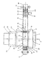
- the drawing shows an embodiment of the invention schematically in plan view.
- the veneer sheets 1 are fed to the device for assembling 2 in the direction of the arrow 3, whereby, as the drawing shows, they are introduced into the longitudinal direction of their fibers and thus also in this way to the rear end of the previously inserted veneer sheet or the one that has arisen up to that point Veneer web be glued.
- the alignment and gluing of adjacent longitudinal edges 4 of the veneer sheets 1 is carried out in a known manner.
- Seen in the direction of flow 3 behind the assembly device 2 there is a clipper 5 of a known type, which cuts off sections of the same length, so-called "veneer formats", from the veneer web formed.
- These veneer formats are conveyed in the direction of arrow 3 to a storage device 6.
- the laminating material web 8 is drawn off from a supply roll 9 in the direction of the arrow 10. This direction is preferably perpendicular to the direction of transport of the veneer formats. So if the latter are placed on the part of the laminating material web located below them and resting on the depositing device 6, this is done with the help of the lamination material web in the depositing device a movement reversal by in particular 90 °. It follows from the above that the feed plane of the veneer formats from the clipper 5 is located above the plane of the laminating material web 8 in the depositing device 9.
- a suitable transfer device ensures that the veneer formats are properly deposited on the lamination material web so that it does not protrude laterally over the longitudinal edges.
- an adhesive stapling device 11 at the discharge end of the depositing device 6. It essentially consists of an deliverable, in particular lifting and lowering, stamp-like device Heating element 12, which is arranged laterally offset in the drawing for the sake of clarity by a plate-like pressure element which is located above it and which can be pivoted away in the direction of arrow 14.
- the heating element 12 is expediently arranged below the lamination material web 8, while the pressure element 13 pivoted into the working position is above the veneer format to be attached.
- the transport continues a press, in particular a short-cycle press 15.
- the veneer format is glued to the entire surface of the lamination material web, which is expediently a press with heated jaws which activate the glue or adhesive of the lamination material web in the entire area of the veneer format.
- the press and the adhesive stapling device expediently work in the same cycle.
- the latter also specifies the cycle for the working stroke of the clipper 5 and it can also be decisive for the gluing of the next veneer sheet 1 to the one previously inserted.
- the outlet of the press 15, that is to say the right end of the press in the drawing, is assigned a take-off device, in particular a pair of take-off rolls 16, for the laminating material web 8 covered with formats.
- the extraction roller pair 16 is arranged between the press 15 and an additional clipper 17. This can be operated optionally.
- the clipper can be actuated in particular when the press is closed. Above all, it is used to cut the lamination material web between two glued formats, so that individual laminated veneer formats are created. They are transported out in the direction of arrow 18.
- the additional clipper 17 is located between the pair of draw-off rollers 16 and a longitudinal format roll-up device 19. With the aid of this device, the laminate material web carrying the veneer formats is wound up if one does not cut through with the aid of the additional clipper 17. Which of the two devices 17 and 19 is actuated depends on the wishes of the customer or further processing steps.
- the formats introduced into the depositing device 6 are moved past the short-cycle press 15 in the same sense of movement. They then arrive at an intermediate transport device 22. Seen in the feed direction 21, this is followed by a stacking device 23 on which the formats 24 are stacked, in particular with the aid of a lifting device 25. With the latter, the formats are not necessarily raised, but may also be reduced in batches by one format thickness at a time until the stack is finished. It can easily be seen that the intermediate transport device 22 can also be omitted and in this case the stacking device 23 directly adjoins the depositing device 6.
- the lamination material web 8 can be covered in the area of the depositing device 6 by means of a sliding or swiveling covering element.
- the transfer plane of the veneer formats 24 from the clipper 5 to the depositing device 6 lies above the plane of the cover member, which is not visible in the plan view. If the latter is in its working position, the formats cannot be transferred to the underlying lamination material web or its supporting surface, but to the cover member. It is preferably a roll-up and roll-off, suitably resilient film, for example made of plastic.
- the format 24 in each case slides particularly well on this. With the aid of the cross conveyor 20 mentioned, it is drawn off from the cover member in the direction of arrow 21 and conveyed to the intermediate transport device 22.
- these formats 24 are non-laminated and they can either be otherwise laminated or processed without laminating. If the covering member or the rollable film is wound up, the lamination material web 8 or its longitudinal guide in the depositing device 6 is accessible again, so that the formats can now be deposited on the lamination material web.
- the laminating material web 8 can be continuously withdrawn from the supply roll 9, one is seen in the feed direction 10 in front of the depositing device 6 and behind the press 15, but in particular behind the additional clipper 17 known device comprising at least three rollers 26, 27 and 28 or 29, 30 and 31 is provided, the middle roller 27 or 30 is designed as a so-called dancer roller, which in each case provides for the formation of a loop that increases and decreases in time. These loops extend downwards perpendicular to the image plane.
Landscapes
- Life Sciences & Earth Sciences (AREA)
- Engineering & Computer Science (AREA)
- Mechanical Engineering (AREA)
- Wood Science & Technology (AREA)
- Forests & Forestry (AREA)
- Veneer Processing And Manufacture Of Plywood (AREA)
Claims (14)
- Machine de fabrication de placages laminés dimensionnés présentant un dispositif pour assembler des feuilles de placage, ainsi qu'une presse pour solidariser une bande d'un matériau de placage et de laminage, caractérisée par le fait que le dispositif (2) d'assemblage des feuilles de placage (1) est réalisé sous la forme d'un dispositif d'assemblage transversal, dont la sortie est reliée à l'entrée d'un massicot (5) ; par le fait qu'un dispositif (6) récepteur des placages dimensionnés (24), associé à la sortie du massicot, fait partie d'un dispositif (7) d'acheminement longitudinal de la bande (8) de matériau de laminage, un rouleau (9) de matériau de laminage ou élément similaire étant associé à la zone initiale du dispositif récepteur (6), et la presse (15) étant associée à sa zone finale ; et par le fait que la direction d'avance (10) de la bande (8) de matériau de laminage s'étend transversalement, en particulier perpendiculairement à celle (3) du dispositif (2) d'assemblage transversal.
- Machine selon la revendication 1, caractérisée par le fait que le dispositif récepteur (6) est relié à un dispositif (11) de fixation par collage, destiné à assujettir les placages dimensionnés (24) à la bande (8) de matériau de laminage.
- Machine selon la revendication 2, caractérisée par le fait que le dispositif (11) de fixation par collage est associé à l'extrémité de délivrance du dispositif récepteur (6).
- Machine selon la revendication 3, caractérisée par le fait que le dispositif (11) de fixation par collage comprend un élément chauffant (12) du type pilon, pouvant être réglé et notamment soulevé et abaissé, ainsi qu'un élément presseur (13) du type plaque qui est également réglable, de préférence escamotable par pivotement latéral.
- Machine selon la revendication 4, caractérisée par le fait que l'élément chauffant (12) se trouve au-dessous du plan de la bande (8) de matériau de laminage, l'élément presseur (13) étant situé au-dessus du plan du placage dimensionné (24) reposant à plat.
- Machine selon au moins l'une des revendications précédentes, caractérisée par le fait que la presse est réalisée sous la forme d'une presse (15) à cadence courte.
- Machine selon au moins l'une des revendications précédentes, caractérisée par le fait qu'un dispositif d'évacuation (16), en particulier une paire de cylindres d'évacuation de la bande garnie (8) de matériau de laminage, est associé à la sortie de la presse.
- Machine selon la revendication 7, caractérisée par le fait que la paire de cylindres d'évacuation (16) est intercalée entre la presse (15) et un massicot additionnel (17).
- Machine selon la revendication 8, caractérisée par le fait que le massicot additionnel (17) est interposé entre la paire de cylindres d'évacuation (16) et un dispositif (19) enrouleur de formats longitudinaux, destiné à la bande (8) de matériau de laminage portant des placages dimensionnés (24).
- Machine selon au moins l'une des revendications précédentes, caractérisée par le fait qu'un convoyeur transversal réglable (20) se trouve au-dessus de la surface de travail du dispositif récepteur (6), la direction de convoyage (21) dudit convoyeur correspondant à celle (3) du dispositif (2) d'assemblage transversal.
- Machine selon la revendication 10, caractérisée par le fait que la bande (8) de matériau de laminage peut être recouverte, dans la région du dispositif récepteur (6), au moyen d'un organe de recouvrement pouvant coulisser ou pivoter, le plan de transfert des placages dimensionnés (24) étant situé, en position de travail, au-dessus du plan de l'organe de recouvrement.
- Machine selon la revendication 11, caractérisée par le fait que l'organe de recouvrement est formé par une feuille enroulable.
- Machine selon au moins l'une des revendications précédentes, caractérisée par le fait que le dispositif récepteur (6) est interposé entre le massicot (5) et un dispositif (22) de transport intermédiaire.
- Machine selon la revendication 13, caractérisée par le fait que le dispositif (22) de transport intermédiaire est interposé entre le dispositif récepteur (6) et un dispositif d'empilement (23) équipé, en particulier, d'un dispositif élévateur (25).
Applications Claiming Priority (2)
| Application Number | Priority Date | Filing Date | Title |
|---|---|---|---|
| DE3600937 | 1986-01-15 | ||
| DE19863600937 DE3600937A1 (de) | 1986-01-15 | 1986-01-15 | Maschine zur herstellung kaschierter furnier-formate |
Publications (3)
| Publication Number | Publication Date |
|---|---|
| EP0230267A2 EP0230267A2 (fr) | 1987-07-29 |
| EP0230267A3 EP0230267A3 (en) | 1989-09-06 |
| EP0230267B1 true EP0230267B1 (fr) | 1991-12-04 |
Family
ID=6291866
Family Applications (1)
| Application Number | Title | Priority Date | Filing Date |
|---|---|---|---|
| EP19870100432 Expired - Lifetime EP0230267B1 (fr) | 1986-01-15 | 1987-01-15 | Machine de fabrication de placages laminés dimensionnés |
Country Status (2)
| Country | Link |
|---|---|
| EP (1) | EP0230267B1 (fr) |
| DE (2) | DE3600937A1 (fr) |
Family Cites Families (3)
| Publication number | Priority date | Publication date | Assignee | Title |
|---|---|---|---|---|
| US3789979A (en) * | 1972-02-17 | 1974-02-05 | T Streckert | Veneer handling apparatus |
| DE8516615U1 (de) * | 1985-04-25 | 1985-10-24 | Carl Rückle Maschinenbau GmbH, 7302 Ostfildern | Vorrichtung zum Beschichten von Furnieren mit Trägermaterial |
| DE3526372A1 (de) * | 1985-07-24 | 1987-02-05 | Rueckle Carl Maschinenbau | Einrichtung zum verarbeiten von furnieren |
-
1986
- 1986-01-15 DE DE19863600937 patent/DE3600937A1/de not_active Withdrawn
-
1987
- 1987-01-15 DE DE8787100432T patent/DE3774886D1/de not_active Expired - Fee Related
- 1987-01-15 EP EP19870100432 patent/EP0230267B1/fr not_active Expired - Lifetime
Also Published As
| Publication number | Publication date |
|---|---|
| DE3600937A1 (de) | 1987-07-23 |
| EP0230267A3 (en) | 1989-09-06 |
| DE3774886D1 (de) | 1992-01-16 |
| EP0230267A2 (fr) | 1987-07-29 |
Similar Documents
| Publication | Publication Date | Title |
|---|---|---|
| EP3150524B1 (fr) | Dispositif d'assemblage | |
| DE2708066C3 (de) | Vorrichtung zum Anbringen von mit Klebstoff versehenen Einfaßstreifen zum Binden von Blattlagen | |
| DE2612373A1 (de) | Leiste mit metallueberzug und verfahren zu ihrer herstellung | |
| DE102007049422A1 (de) | Waben-Wellpappen-Anlage | |
| EP2517892B1 (fr) | Dispositif et procédé de fabrication d'un bloc de livre relié présentant une bande à onglets ou une couverture | |
| DE2228631A1 (de) | Vorrichtung zum aneinanderkleben von bandfoermigem material | |
| DE102007049426A1 (de) | Wellpappe-Streifen-Wende-Vorrichtung | |
| DE3510147A1 (de) | Vorrichtung zum beleimen streifenfoermiger flaechen zweier werkstuecke | |
| DE1912150B2 (de) | Verfahren und bogenkaschiermaschine zum zufuehren der kaschiersaetze zur presswalze | |
| DE3440958C2 (fr) | ||
| DE69501458T2 (de) | Vorrichtung zur stückweisen Abgabe von Broschüren zu einer Aufnahmestation und Abgabeverfahren ausgeführt durch die genannte Vorrichtung | |
| DE1871629U (de) | Buchblock-hinterklebe- und kaptalmaschine. | |
| EP0230267A2 (fr) | Machine de fabrication de placages laminés dimensionnés | |
| EP0662438A1 (fr) | Dispositif pour alimenter en continu une bande dans un dispositif de traitement de bandes | |
| EP0199841B1 (fr) | Dispositif pour enduire des placages avec un film support et procédé exécuté avec ce dispositif | |
| DE4217878A1 (de) | Lätzchen | |
| DE10134508A1 (de) | Verfahren zum Zusammenfassen von Beuteln, Vorrichtung zur Durchführung des Verfahrens und Beutelkette, sowie Beutelstapelkette | |
| DE69906326T2 (de) | Vorrichtung zum verpacken von im scheiben geschnittenen lebensmitteln | |
| EP4116244A1 (fr) | Dispositif et processus de l'industrie de transformation du tabac permettant de relier deux bandes de matière | |
| WO1995009767A1 (fr) | Dispositif pour l'emballage de pieces entre deux feuilles continues | |
| EP2388149B1 (fr) | Dispositif de tronçonnage et d'amenée de pièces de dos pour une machine à fabriquer des couvertures de livre | |
| DE2021097C (de) | Verfahren und Vorrichtung fur das gleichzeitige Zufuhren mehrerer Lagen eines biegsamen bahnformigen Materials zu einer schrittweise arbeitenden Bear beitungsmaschine | |
| EP0681957A1 (fr) | Procédé et dispositif pour envelopper des parallélépipèdes, en particulier des balles en matière isolante avec du matériel à envelopper | |
| DE1761361C (de) | Verfahren und Vorrichtung zum Festkleben des freien Endes von zu Rollen aufgewickelten blattförmigen Werkstoffen an der Oberfläche der Rollen | |
| DE3226454C2 (de) | Vorrichtung zum Verbinden und Fördern von aus Platten geschnittenen Streifen |
Legal Events
| Date | Code | Title | Description |
|---|---|---|---|
| PUAI | Public reference made under article 153(3) epc to a published international application that has entered the european phase |
Free format text: ORIGINAL CODE: 0009012 |
|
| AK | Designated contracting states |
Kind code of ref document: A2 Designated state(s): CH DE FR IT LI |
|
| PUAL | Search report despatched |
Free format text: ORIGINAL CODE: 0009013 |
|
| AK | Designated contracting states |
Kind code of ref document: A3 Designated state(s): CH DE FR IT LI |
|
| 17P | Request for examination filed |
Effective date: 19890907 |
|
| 17Q | First examination report despatched |
Effective date: 19910311 |
|
| GRAA | (expected) grant |
Free format text: ORIGINAL CODE: 0009210 |
|
| AK | Designated contracting states |
Kind code of ref document: B1 Designated state(s): CH DE FR IT LI |
|
| PGFP | Annual fee paid to national office [announced via postgrant information from national office to epo] |
Ref country code: FR Payment date: 19911210 Year of fee payment: 6 |
|
| PGFP | Annual fee paid to national office [announced via postgrant information from national office to epo] |
Ref country code: CH Payment date: 19911216 Year of fee payment: 6 |
|
| REF | Corresponds to: |
Ref document number: 3774886 Country of ref document: DE Date of ref document: 19920116 |
|
| ITF | It: translation for a ep patent filed | ||
| PGFP | Annual fee paid to national office [announced via postgrant information from national office to epo] |
Ref country code: DE Payment date: 19920319 Year of fee payment: 6 |
|
| ET | Fr: translation filed | ||
| PLBE | No opposition filed within time limit |
Free format text: ORIGINAL CODE: 0009261 |
|
| STAA | Information on the status of an ep patent application or granted ep patent |
Free format text: STATUS: NO OPPOSITION FILED WITHIN TIME LIMIT |
|
| 26N | No opposition filed | ||
| PG25 | Lapsed in a contracting state [announced via postgrant information from national office to epo] |
Ref country code: LI Effective date: 19930131 Ref country code: CH Effective date: 19930131 |
|
| PG25 | Lapsed in a contracting state [announced via postgrant information from national office to epo] |
Ref country code: FR Effective date: 19930930 |
|
| REG | Reference to a national code |
Ref country code: CH Ref legal event code: PL |
|
| PG25 | Lapsed in a contracting state [announced via postgrant information from national office to epo] |
Ref country code: DE Effective date: 19931001 |
|
| REG | Reference to a national code |
Ref country code: FR Ref legal event code: ST |
|
| PG25 | Lapsed in a contracting state [announced via postgrant information from national office to epo] |
Ref country code: IT Free format text: LAPSE BECAUSE OF NON-PAYMENT OF DUE FEES;WARNING: LAPSES OF ITALIAN PATENTS WITH EFFECTIVE DATE BEFORE 2007 MAY HAVE OCCURRED AT ANY TIME BEFORE 2007. THE CORRECT EFFECTIVE DATE MAY BE DIFFERENT FROM THE ONE RECORDED. Effective date: 20050115 |