EP0230283B1 - Öffentliches Fernsprechsystem und -Gerät - Google Patents
Öffentliches Fernsprechsystem und -Gerät Download PDFInfo
- Publication number
- EP0230283B1 EP0230283B1 EP87100489A EP87100489A EP0230283B1 EP 0230283 B1 EP0230283 B1 EP 0230283B1 EP 87100489 A EP87100489 A EP 87100489A EP 87100489 A EP87100489 A EP 87100489A EP 0230283 B1 EP0230283 B1 EP 0230283B1
- Authority
- EP
- European Patent Office
- Prior art keywords
- mex
- connection
- modular
- tain
- modular process
- Prior art date
- Legal status (The legal status is an assumption and is not a legal conclusion. Google has not performed a legal analysis and makes no representation as to the accuracy of the status listed.)
- Expired
Links
- 238000000034 method Methods 0.000 claims description 55
- 230000008569 process Effects 0.000 claims description 54
- 239000000523 sample Substances 0.000 claims description 53
- 230000015654 memory Effects 0.000 claims description 42
- 239000000872 buffer Substances 0.000 claims description 11
- 230000006870 function Effects 0.000 claims description 10
- 238000004891 communication Methods 0.000 claims description 8
- 238000012545 processing Methods 0.000 claims description 6
- 230000011664 signaling Effects 0.000 claims description 6
- 238000003780 insertion Methods 0.000 claims description 5
- 230000037431 insertion Effects 0.000 claims description 5
- 230000005540 biological transmission Effects 0.000 claims description 3
- 238000009795 derivation Methods 0.000 claims description 3
- 239000011159 matrix material Substances 0.000 claims description 3
- 230000003287 optical effect Effects 0.000 claims description 3
- 238000010200 validation analysis Methods 0.000 claims description 3
- 102100024058 Flap endonuclease GEN homolog 1 Human genes 0.000 claims description 2
- 101000833646 Homo sapiens Flap endonuclease GEN homolog 1 Proteins 0.000 claims description 2
- 101150044561 SEND1 gene Proteins 0.000 claims description 2
- 238000012360 testing method Methods 0.000 claims description 2
- 238000012546 transfer Methods 0.000 claims description 2
- 238000010586 diagram Methods 0.000 description 11
- 230000004224 protection Effects 0.000 description 6
- 230000007257 malfunction Effects 0.000 description 4
- 238000013478 data encryption standard Methods 0.000 description 2
- 238000009434 installation Methods 0.000 description 2
- 239000010453 quartz Substances 0.000 description 2
- 230000004044 response Effects 0.000 description 2
- VYPSYNLAJGMNEJ-UHFFFAOYSA-N silicon dioxide Inorganic materials O=[Si]=O VYPSYNLAJGMNEJ-UHFFFAOYSA-N 0.000 description 2
- 102100028043 Fibroblast growth factor 3 Human genes 0.000 description 1
- 102100024061 Integrator complex subunit 1 Human genes 0.000 description 1
- 101710092857 Integrator complex subunit 1 Proteins 0.000 description 1
- 108050002021 Integrator complex subunit 2 Proteins 0.000 description 1
- 102100039131 Integrator complex subunit 5 Human genes 0.000 description 1
- 101710092888 Integrator complex subunit 5 Proteins 0.000 description 1
- 230000004913 activation Effects 0.000 description 1
- 230000006978 adaptation Effects 0.000 description 1
- 239000013256 coordination polymer Substances 0.000 description 1
- 238000013500 data storage Methods 0.000 description 1
- 238000013461 design Methods 0.000 description 1
- 238000009792 diffusion process Methods 0.000 description 1
- 230000000694 effects Effects 0.000 description 1
- 238000005516 engineering process Methods 0.000 description 1
- 238000009413 insulation Methods 0.000 description 1
- 230000010354 integration Effects 0.000 description 1
- 238000002955 isolation Methods 0.000 description 1
- NBNNDUZYMXBCOX-UHFFFAOYSA-N n-[4-[4-(4-methoxyphenoxy)-2,6-dimethylphenyl]-1,3-thiazol-2-yl]pyridine-4-carboxamide Chemical compound C1=CC(OC)=CC=C1OC(C=C1C)=CC(C)=C1C1=CSC(NC(=O)C=2C=CN=CC=2)=N1 NBNNDUZYMXBCOX-UHFFFAOYSA-N 0.000 description 1
- 230000000737 periodic effect Effects 0.000 description 1
- 238000011084 recovery Methods 0.000 description 1
- 230000008054 signal transmission Effects 0.000 description 1
Images


Classifications
-
- H—ELECTRICITY
- H04—ELECTRIC COMMUNICATION TECHNIQUE
- H04M—TELEPHONIC COMMUNICATION
- H04M17/00—Prepayment of wireline communication systems, wireless communication systems or telephone systems
-
- H—ELECTRICITY
- H04—ELECTRIC COMMUNICATION TECHNIQUE
- H04M—TELEPHONIC COMMUNICATION
- H04M17/00—Prepayment of wireline communication systems, wireless communication systems or telephone systems
- H04M17/02—Coin-freed or check-freed systems, e.g. mobile- or card-operated phones, public telephones or booths
- H04M17/023—Circuit arrangements
Definitions
- the present invention relates to a pubic telephone system and apparatus, suitable for the insertion of telephonic terminals of various types, as well as for the insertion of telematic terminals.
- telephonic terminal defines the following:
- the term "telematic terminal” defines the following:
- a public telephone system preset for the connection of at least a plurality of telephonic terminals is already known from EP-0 066 823.
- a public telephone system and apparatus comprising a group of centralized logics operatively and bidirectionally connected to matching groups of telephonic terminals, are already known from Italian patent no. 1.078.601 by the same Applicant; said group of logics being controlled by a supervisor device.
- the telephone set receives the tokens and/or the coins, counts them and transmits the credit data, together with the digits of the number being dialled, to the centralized logic.
- the centralized logic upon acquisition of the credit data, computes a collection algorithm which is a function of the dialled digits and transmits collection commands to the telephone set, the sequence of the commands being selectively determined by said algorithm.
- Each logic furthermore receives from the supervisor (located barycentrically with respect to the system) all the data which may be programmed and updated. In turn, the supervisor receives from the logics the statistical data related to the telephonic traffic and to the general alarms.
- Each centralized logic is preset to control a group of ten repeaters, each of which interfaces with a matching telephone set.
- the supervisor is preset to control a group of 64 logics (eight-wire bus, equivalent to 2 n combinations) so that the system, in its entirety, is preset for the optimum connection of 640 telephones.
- This number of controllable telephone sets which derives directly from the architecture of the system, may cause some limitations.
- the system is rigid and is not economically advantageous on the one hand for application in small exchanges, and on the other hand for implementations with a small number of telephone sets in addition to the group of 640 which saturate such a system. In both cases, the installation or respectively the duplication of the system may in fact turn out to be excessively redundant.
- the centralized logics differ both circuitally and at the program level according to the type of the interfaced telephone set and are particularly complex in the case of telematic terminals and of paycard terminals, which furthermore require particular and expensive adaptations of the system at the centralized level.
- the present invention has the important object of providing a system and a apparatus capable of controlling, in exchanges of any size and technology, with substantially levelled costs, all the known and foreseeable public telephone sets, as well as the telematic terminals of the type specified.
- the present invention relates to an improved public telephone system, as defined in the appended claims.
- the system comprises at least one system serial bus to which a plurality of modular process units is connected in parallel, each of which is intended for controlling at least one pair of specialized probes for connection to matchingly specialized telephonic and non-telephonic terminals; at least one modular process unit, acting as master with respect to the other units connected to the serial bus, said modular process unit being connected - via modem and switched or dedicated data-transmission line- to one or more remote control and/or supervision and/or data concentration centers.
- the system is provided with a second serial bus to which the modular process units are connected, together with at least one extended process memory storing data files related to specialized control of said terminals; said extended memory being provided with a microprocessor control logic which controls the modular process units connected to said second bus with a preset scanning pattern, preferably of the polling type with privileged dynamics.
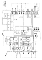
- CEN indicates the telephone exchange
- NTP generally indicates the apparatus of the system according to the present invention.
- the apparatus comprises, located in a centralized region, a plurality of modular process units, TAI1...TAIn which are connected in parallel to at least one serial bus interconnecting these process units for the functions which will be specified hereinafter.
- the system and the apparatus are preset for controlling terminals of different kinds and are therefore provided with a first and a second serial bus BB1, BB2 interconnecting, besides the modular process units TA1, a pair of extended process memories MEX-I1, 2 which will be described hereinafter.
- Each modular unit TAI has a microprocessor to provide the following system functions:
- the parallel connection on the serial bus BB1 allows, among other things, reloading and initializing of one or more modular units TAI subsequent to possible dropouts due to power failures or due to generic disabling events.
- the system is provided with a plurality of modular units TAI, one of said units may act as master with respect to the remaining ones and the programs to be reloaded are taken therefrom.
- the modular unit acting as master is also connected, via a modem unit MMOD and a switched line LC, to a per se known remote center TCS, acting as a loading center.
- the unit MMOD besides acting as a modem, is also provided with its own memories to store, as will be specified hereinafter, a copy of the counters stored in the modular units TAI.
- Each modular processing unit TAI is connected to a group of telephone or telematic terminals through a pair of specialized transfer modules, hereinafter termed probes, the nature of which varies according to the type of terminal connected thereto.
- probes the nature of which varies according to the type of terminal connected thereto.
- the following three types of probe are considered:
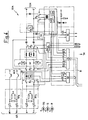
- MP indicates the microprocessor in its entirety. In this microprocessor, the following functional blocks are integrated:
- the diagram of Fig. 2 furthermore illustrates the "transceiver" buffers TR1, TR2 of the two system buses BB1, BB2, with the related protections; the additional interface of the system bus INT1 towards the MMOD module, a first tone generator GEN1 suitable for generating, towards the telephone set (terminal), the exchange tone at 425Hz (free-engaged); a second tone generator GEN2 at 1000 Hz, generating the beep tone for end-of-credit, the interface INB for extending, towards the probes, the internal data and address bus BI.
- a first tone generator GEN1 suitable for generating, towards the telephone set (terminal), the exchange tone at 425Hz (free-engaged)
- a second tone generator GEN2 at 1000 Hz, generating the beep tone for end-of-credit, the interface INB for extending, towards the probes, the internal data and address bus BI.
- each unit TAI is provided with an autonomous power supply DC/DC suitable for feeding also the probe modules, and with a group of three optical indicators L1, L2, L3 respectively for operativity, major alert and minor alert.
- Each SUT probe mutiplexes five interface units, indicated at IU in Fig. 3, each connecting one telephone set of the indicated type to the TAI unit and being enabled by a common analog multiplexer MUX and associated latch LA.
- Fig. 3 depicts only one of these interface units, which however in the practical implementation are physically repeated five times on each module SUT. Naturally, the fivefold provision is not limitative, since it depends on a mere design choice.
- Each interface unit IU is enabled in sequence by an enable signal en stored in the latch register LA of the unit TAI.
- the command en sets the analog multiplexer MUX so as to enable the selected interface.
- the multiplexer MUX receives the counter co , check ri and engagement im signals arriving from the corresponding terminal, via a repeater T, on the leads c , r and b . All the signals are filtered by related attenuation and protection circuits AP1-AP3.
- the engagement signal is taken as a derivation on the audio lead b in electromechanical exchanges, serially in numeric exchanges. In the first case, the derivation enters the interface unit of the probe at the point IN and, filtered by the circuit AP3, reaches the multiplexer MUX.
- the lead b is interrupted, the engagement signal enters at the point IN, returns onto the lead b from the point OUT after triggering an opto-isolator OT which allows the passage of an engagement signal reproduced towards the multiplexer MUX.
- the latch LA furthermore stores commands coming from the modular unit TAI and actuating correspondent circuits CO which generate and send to the telephone set, through a protection circuit CP, the disconnection signal dis and collection signal inc . From the latch LA, furthermore, a command is issued which lights a luminous indicator as by means of which the modular unit TAI has the possibility of indicating a failure related to the SUT probe.
- This probe comprises the repeaters for the telephone sets of the G+M, CCT and CDT types.
- Each probe is preferably structured for controlling two telephone sets, each set being connected to the probe by means of four leads: audio a , b and signalling a s , b s .
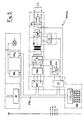
- Fig. 4 illustrates schematically the circuitry related to only one repeater, which however in the practical implementation is physically repeated two (or more) times on the same probe.
- the interface of the probe SGM towards the modular unit TAI is the same described previously for the module SUT; the two probes are thus interchangeable in the same rack (pin-to-pin compatibility) depending on the need to control, by means of the modular unit TAI, telephone sets of one kind of of the other.
- the diagram illustrates the connection towards the exchange CEN on the right side; the connection towards the terminal (telephone set) AP on the left side and the commands and signals to and from the modular unit TAI (bottom).
- the pairs of leads a , b , as , bs for connection to the terminal are shown, both protected against overvoltages and shortcircuits by related protection circuits AP4, AP5.
- the engagement and selection criteria are taken on the lead a ; the signals originating from the terminal are taken from the leads as , bs .
- the following signals are taken: the 425 Hz tone, the 12KHz counter or, alternatively, the DC count (from the lead z ) as well as the ring signal.
- the ring signal ri taken by means of a correspondent ring probe SR, and the DC count signal are sent to the modular unit TAI as analog signals.
- the switch AS is enabled by the same unit TAI by means of an enable command en stored in a latch LA1.
- BU indicates a buffer register, connected to the interface INB for the extension of the internal bus of the unit TAI.
- this buffer the following data are stored to be sent to the unit TAI: selection engagement is originating from the correspondent probe SIS sensing the engagement condition; signals ss originating from a power supply and signalling circuit ALS connected to the leads as , bs ; 12 KHz count c12 and 425 Hz tone t425 originating from corresponding probes S425, S12K which will be described hereinafter.
- the following actuation commands arrive for the correspondent circuits and components specified hereinafter:
- the probe is completed by four optical warning indicators for disconnection DIS, selection engagement IS and polarity inversion IP.
- a probe S2F may in any case be defined by a generic and known MODEM having a serial/parallel interface UART also of a known kind, associated to the probe SGM described previously. This combination is not illustrated in detail since its specialized circuital structure is not within the scope of the protection of the present invention.
- This module comprises an internal bus MBI intended to connect, by means of an interface IB, to the bus of the microprocessor MP of the modular unit TAI (chosen as master) thereby defining by all means an extension of the bus of the microprocessor.
- On the internal bus MBI two or more RAM memory banks MM1, MM2 are connected, which, in view of the bus MBI being interfaced with the modular unit, may be used for back-up of the data related to the counters present on the memories of the different units TAI which compose the system. These data are taken from the units TAI of the system with a continuous-scanning algorithm (polling).
- a buffer power supply circuit CAT is provided for keeping the same memories supplied with power - in case of power failure - for a period of time sufficient for the system recovery.
- CLL indicates an interface read circuit capable of taking, from a cabled matrix MMC, a code cabled at system level, representing a telephone number related to a center which, by means of a switched line LC, is called automatically, if there are no program-tabled intervention telephone numbers or if the same are unusable.
- a protection circuit AP6 Connected to the switched line LC, a protection circuit AP6, an engagement and selection circuit IMP and, by means of a line interface ILL, a modem MOD, are arranged.
- UST indicates a serial port connected to a modem MOD for reception, transmission and modem control.
- an port block I/O is furthermore connected, from which, by means of a tone probe S425, the microprocessor of the unit TAI receives the exchange tone signal and, by means of a ring probe SR, the calling ring.
- the microprocessor can furthermore control the engagement and selection circuit IMP.
- the block MMOD furthermore takes the +5V and ⁇ 12V and ground power supplies from the TAI unit.
- each unit MEX-I is provided with the following components:
- the unit MEX-I controls the group of the TAI units connected on the credit-debit bus BB2 according to a polling scanning with privileged dynamics.
- the unit TAI containing probes SGM for connection to CDT or CCT sets are scanned with a preset period such as to ensure a system response adequate to the external variations.
- the unit TAI sending such criterion is assigned to a group of privileged units with a higher scanning rate to ensure an adequate online response.
- the above unit TAI returns to the normal polling level.
- the unit MEX-I employs the second bus BB2. If a failure disables the bus BB2, the unit MEX-I switches onto the first bus BB1, slowing down the operations of updating of the duplicated counters present on the module MMOD.
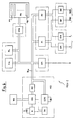
- Fig. 6 illustrates the functional block diagram of the unit MEX-I and its connections to the other modular units of the system (TAI and MMOD) as well as to the duplicate unit MEX-I.
- MCU indicates the microprocessor integrating the CPU, the decoder circuit DEC for decoding the addresses on the internal bus BIm, the clock K driven by a quartz Q at 8 MHz and a coprocessor CCPU capable of autonomously processing the cryptography algorithm according to the well-known DES (Data Encryption Standard).
- the coprocessor CCPU operates with a clock frequency of its own, e.g. at 10 MHz.
- the block MCU furthermore contains a timer TM with different levels (e.g. four) of interrupt programable with a preset base frequency, e.g. 2 ms.
- a watchdog circuit WD is arranged to control the correct operation of the CPU.
- the WD circuit is retriggered by the CPU. In the absence of a retrigger, this circuit activates an alarm which allows a role swap to be carried out between the two duplicate MEX-I units according to the well-known master/slave configuration.
- the internal bus BIm is connected with the program memories PM of the EPROM type, the work memories ML of the RAM type and the file memories MA composed of banks (1 to 8) m1...m8 of dynamic RAMs. To each byte of the file memories, a parity bit is added which is automatically validated at every read/write operation.
- the file memory is preferably handled in "pages", having, e.g., a 32-Kbyte size.
- a circuit GGM automatically provides the logical/physical control in the overall space of the total bytes.
- SPI Serial Programmable Interface
- IIM indicates the interfaces (two, for reasons of reliability) for the double connection of the units MEX-I
- IB1, IB2 indicate the interfaces for the connections to the system bus BB1, BB2.
- the interfaces IIM and IB1, IB2 are connected to the internal bus BIm through serial I/O ports P1, P2.
- the interface IB2 is normally active for the connection on the system bus BB2 and only in case of malfunction of this bus the interface IB1 is activated.
Landscapes
- Engineering & Computer Science (AREA)
- Computer Networks & Wireless Communication (AREA)
- Computer Security & Cryptography (AREA)
- Signal Processing (AREA)
- Telephonic Communication Services (AREA)
- Sub-Exchange Stations And Push- Button Telephones (AREA)
- Interface Circuits In Exchanges (AREA)
Claims (29)
- Öffentliches Telefonsystem, voreingestellt für die Verbindung mindestens einer Vielzahl von Telefonanschlüssen, gekennzeichnet durch: mindestens einen seriellen Systembus (BB1, BB2); eine Vielzahl von modularen Prozeßeinheiten (TAI1...TAIn) parallel verbunden mit dem seriellen Systembus, wobei jede der modularen Prozeßeinheiten zum Steuern mindestens eines Paars von Sonden (SUT, SGM, S2F) bestimmt ist, die für die Verbindung mit übereinstimmend spezialisierten Telefon- und Nichttelefon-Anschlüssen spezialisiert sind; mindestens eine modulare Master-Prozeßeinheit (TAI1), die als Master gegenüber den anderen mit dem seriellen Bus verbundenen Einheiten wirkt, wobei die modulare Master-Prozeßeinheit (TAI1) - über ein Modem (MMOD) und geschaltete oder dedizierte Datenübertragungs-Telefonleitungen (LC) - mit einem oder mehreren ortsfesten Steuer- und/oder Aufsichts- und/oder Datenkonzentrierungszentren (TCS) verbunden ist.
- Öffentliches Telefonsystem nach Anspruch 1, dadurch gekennzeichnet, daß jede modulare Prozeßeinheit (TAI1...TAIn) einen Mikroprozessor (MP) zur Schaffung der folgenden Systemfunktionen enthält:- Verbindung mit dem zugeordneten Anschluß für Verbindungen- Analog-Signalbehandlung für und von dem zugeordneten Anschluß- Betriebssteuerungsowie nichtflüchtige Speicher (Ml, M3) und RAMs (M2, M4), wobei die nichtflüchtigen Speicher zum Abspeichern der Systemparameter und Tabellen und die RAMs zum Abspeichern der sich auf die Zähler der zugeordneten Anschlüsse beziehenden Daten und der Anwendungsprogramme geeignet sind.
- Öffentliches Telefonsystem nach Anspruch 1 oder 2, dadurch gekennzeichnet, daß die Verbindung zwischen den modularen Prozeßeinheiten (TAI1...TAIn) und den telefonischen und nichttelefonischen Anschlüssen (U+I, U+IP, Tx3c, G+M, CCT, CDT, TT) mit drei verschiedenen Arten spezialisierter Sonden (SUT, SGM, S2F) versehen ist, wobei die verschiedenen Arten spezialisierter Sonden direkt entsprechende äußere Verbinder zur Verbindung mit den modularen Prozeßeinheiten aufweisen und daher wechselseitig austauschbar sind.
- Öffentliches Telefonsystem nach Anspruch 1 und 3, dadurch gekennzeichnet, daß eine erste Art von Sonde (SUT) eine Schnittstelle zwischen zur Verfügung stehenden Telefonwiederholern (T1...T5) und der modularen Prozeßeinheit (TAI) bildet, daß eine zweite Art von Sonde (SGM) einen Wiederholer für Fernsprechapparate (G+M, CCT, CDT) mit einer Zwei-Leitungspaarverbindung - Audio und Signal - bildet, und daß eine dritte Art von Sonde (S2F) einen Wiederholer für Telematik-Anschlüsse und die Telefonapparate (TT) bildet, die Verbindungen mit nur zwei Leitungen verwenden.
- Öffentliches Telefonsystem nach Anspruch 1, dadurch gekennzeichnet, daß die modulare Master-Prozeßeinheit (TAI1) mit dem ortsfernen Steuerzentrum (TCS) durch eine Verbindungseinheit verbunden ist, die ein Modem (MMOD) und eine Vielzahl von Speichern zum Abspeichern einer Kopie der Zähler jeder modularen Prozeßeinheit (TAI1...TAIn) aufweist.
- Öffentliches Telefonsystem nach Anspruch 1, gekennzeichnet durch einen ersten (BB1) und einen zweiten (BB2) seriellen Bus, mit dem neben den modularen Prozeßeinheiten (TAI1...TAIn) Zweitexemplare von vergrößerten Prozeßspeichern (MEX-I1, MEX-I2) parallel verbunden sind, die selektiv für die Zuverlässigkeit aktiviert werden können und Telefonanschlüsse mit Telefonkarten steuern.
- Öffentliches Telefonsystem nach Anspruch 6, dadurch gekennzeichnet, daß die vergrößerten Prozeßspeicher (MEX-I1, MEX-I2) eine Mikroprozessor-Steuerlogik (MCU) aufweisen, die die modularen Prozeßeinheiten (TAI1... TAIn) steuern, wenn sie mit dem zweiten seriellen Bus (BB2) mit einer voreingestellten Exkursion und mit bevorrechtigten dynamischen Verhalten verbunden sind.
- Öffentliches Telefonsystem nach Anspruch 7, dadurch gekennzeichnet, daß die vergrößerten Prozeßspeicher (MEX-I1, MEX-I2) Dateispeicher (MM1, MM2) für Listen von für ungültig erklärten Telefonkarten oder Codes, Steueralgorithmen, Steuerparameter und Verkehrsdatenpuffer aufweisen.
- Öffentliches Telefonsystem nach Ansprüchen 6 bis 8, dadurch gekennzeichnet, daß der zweite serielle Bus (BB2) für den Austausch von bearbeiteten Daten mit den vergrößerten Prozeßspeichern (MEX-I1, MEX-I2) bestimmt ist und durch deren Einsetzung aktiviert wird.
- In dem öffentlichen Telefonsystem nach den Ansprüchen 1 bis 9 verwendete Vorrichtung, dadurch gekennzeichnet, daß sie eine Vielzahl modularer Prozeßeinheiten (TAI1...TAIn) aufweist, die parallel mit mindestens einem seriellen Bus (BB1, BB2) verbunden und mit Hilfe von dedizierten Sonden (SUT, SGM, S2F) mit öffentlichen Telefonund Telematik-Anschlüssen (U+I, U+IP, Tx3c, G+M, CCT, CDT, TT) verbunden sind, die von dem System gesteuert werden, und daß jede modulare Prozeßeinheit enthält:- einen Mikroprozessor (MP) mit einer Betriebsprüfungs-Steuerschaltung (WD) vom Wachhund-Typ, ansprechend auf einen Rücksetzbefehl und beim Fehlen des Befehls einen Alarm in Richtung auf die Vermittlung CEN) erzeugend,- ein Unterbrecherelement (S1, S2) für den seriellen Bus (BB1, BB2), aktiviert von der Betriebsprüfungs-Steuerschaltung (WD) und durch eine Programm;- Vergleichsschaltungen (COM, D/A) für die Umwandlung von analog nach digital und umgekehrt,- modulare Einheitsverbindungs- (SCI) und Auswahl(WV)-Schaltungen, wobei die Verbindungsschaltung (SCI) zum Erkennen von an die zugeordnete Einheit adressierten Botschaften geeignet ist und deren Empfang erlaubt und wobei die Auswahlschaltung (WV) zum Aussondern jeder anderen Meldung mit einer verschiedenen Adresse bestimmt ist,- einen Satz von Speicherbänken (M1-M4) für die Speicherung von Betriebsprogrammen, von Zählern, von Systemdaten und von erneuerbaren Programmen,- einen ersten und einen zweiten Tongenerator (GEN1, GEN2) bei 425 Hz für den Wählton bzw. bei 1000 Hz für das Ende des Kredits,- eine Schnittstelle (INB) zur Verlängerung eines internen Busses (BI),- eine autonome Leistungsversorgung (DC/DC),- optische Betriebsanzeiger (L1-L3),worin mindestens eine modulare Prozeßeinheit (TAI1), die als Master gegenüber den anderen modularen Prozeßeinheiten (TAI2...TAIn) arbeitet, über ein Modem (MMOD) und geschaltete (LC) oder dedizierte Datenübertragungs-Telefonleitungen mit einem ortsfernen Zentrum zum Datenladen und zum Konzentrieren verbunden ist.
- Vorrichtung nach Anspruch 10, dadurch gekennzeichnet, daß mindestens eine modulare Prozeßeinheit (TAI1) und eine oder mehr dieser zugeordnete dedizierte Sonden (SUT) zur Verbindung mit Telefongeräten des U+I-, U+IP-und Tx3c-Typs vorgesehen sind.
- Vorrichtung nach Anspruch 11, dadurch gekennzeichnet, daß jede dedizierte Sonde (SUT) eine Vielzahl von Schnittstelleneinheiten (IU) jeweils zur Verbindung mit einem übereinstimmenden Telefongerät aufweist, jede Schnittstelleneinheit von einem Multiplexer (MUX) entsprechend einem Befehl der zugeordneten modularen Prozeßeinheit (TAI1...TAIn) ausgewählt wird, wie in einer Latch-Einheit (LA) der Sonde gespeichert wird, und daß der Multiplexer ein Besetztsignal (im) von einem Audiodraht (b) empfängt, der in Umleitung im Falle elektromechanischer Vermittlungsstellen und in Reihe im Fall digitaler Vermittlungsstellen verbunden ist.
- Vorrichtung nach Anspruch 12, dadurch gekennzeichnet, daß die Reihenverbindung des Audiodrahts (b) einen Opto-Isolator (OT) für den Durchgang eines reproduzierten Besetztsignals zu dem Multiplexer (MUX) aufweist.
- Vorrichtung nach Anspruch 10, dadurch gekennzeichnet, daß mindestens eine modulare Prozeßeinheit (TAIn-2, TAIn-1) und eine oder mehr dieser zugeordnete dedizierte Sonden (SGM) zur Verbindung mit Telefonapparaten des G+M-Typs vorgesehen sind.
- Vorrichtung nach Anspruch 14, dadurch gekennzeichnet, daß jede dedizierte Sonde (TAIn-2, TAIn-1) zwei Telefonapparate jeweils mit Hilfe zweier Paare von Drähten steuert, nämlich Audio- (a, b) und Signaldrähten (a s, b s).
- Vorrichtung nach Anspruch 10, 14 und 15, dadurch gekennzeichnet, daß die dedizierte Sonde (SGM) enthält:- einen Analogschalter (AS), der von der modularen Prozeßeinheit (TAI) zum Übertragen eines Anrufsignals (ri) eingeschaltet wird;- einen Vergrößerungspuffer (BU) zum Vergrößern des internen Bus (BI) der modularen Prozeßeinheit, um dadurch die folgenden Daten zu speichern und zu der modularen Prozeßeinheit zu senden: Anwahl-Einschaltung (is), Signal (ss), Zählen (C12) und Ton (t425),- einen Schalter (LA1), der von der modularen Prozeßeinheit die folgenden Befehle empfängt: Unterbrechung der Verbindung (dis), Polaritätsumkehrung (ip), Umgehung (mp), Tonübertragung (it), Tonauswahl (st), Auswahl-Anschaltung (is) und Testkommando (te).
- Vorrichtung nach Ansprüche 14 bis 16, dadurch gekennzeichnet, daß die dedizierte Sonde (SGM) einen Satz von drei Relais (R1-R3) aufweist, für die Verbindung, die Umgehung bzw. das Einsetzen der tonerzeugenden Schaltung.
- Vorrichtung nach Anspruch 10, dadurch gekennzeichnet, daß mindestens eine modulare Prozeßeinheit (TAIn) und eine oder mehr zugeordnete dedizierte Sonden (S2F) für die Verbindung auf zwei Drähten übereinstimmender Telematik-Anschlüsse (TT) vorgesehen sind.
- Vorrichtung nach Anspruch 18, dadurch gekennzeichnet, daß die dedizierte Sonde (TAIn) mindestens ein Modem unter Einschluß eines seriellen/parallelen UART-Ports aufweist.
- Vorrichtung nach Anspruch 10, dadurch gekennzeichnet, daß die als Master wirkende modulare Prozeßeinheit (TAI1) mit dem ortsfernen Steuer- und/oder Überwachungs-und/oder Datenkonzentrierungs-Zentrum (CEN) durch Verbindungsmittel (MMOD) verbunden ist, die einen internen Bus (MBI) aufweisen, der durch eine Schnittstelle (IB) mit dem internen Bus (BI) der modularen Prozeßeinheit verbunden ist und hierfür eine Verlängerung bildet, sowie mit dem internen Bus (MBI) der Verbindungsmittel (MMOD) verbundene Speicherbänke (MM1, MM2) zur Duplikatbildung von Daten der modularen Prozeßeinheiten (TAI1...TAIn), insbesondere der Zähler, wobei die Daten von den modularen Einheiten durch einen kontinuierlich abrufenden Abtastalgorithmus entnommen werden.
- Vorrichtung nach Anspruch 20, dadurch gekennzeichnet, daß die Verbindungsmittel (MMOD) eine verkabelte Matrix (MMC) aufweisen, die permanent eine Interventions-Telefonnummer für Alarme und eine Leseschnittstelle (CLL) für die verkabelte Matrix aufweist.
- Vorrichtung nach Anspruch 20 und 21, dadurch gekennzeichnet, daß die Verbindungsmittel (MMOD) weiterhin eine Telefonleitung (LC) aufweisen, die durch eine Leitungsschnittsstelle (ILL) mit einem mit einem seriellen Steueranschluß (UST) zusammenwirkenden Modem (MOD) verbunden ist.
- Vorrichtung nach Ansprüchen 20 bis 22, dadurch gekennzeichnet, daß auf der Telefonleitung (LC) eine Wahleinschaltschaltung (IMP), eine Anwählsonde (SR) und eine Tonsonde (S425) eingesetzt werden und mit dem internen Bus (MBI) der Verbindungsmittel (MMOD) durch einen Eingangs-/Ausgangsanschluß (I/O) verbunden sind.
- Vorrichtung nach Ansprüchen 10 und 14, dadurch gekennzeichnet, daß die zur Verbindung mit Telefonapparaten des G+M-Typs vorgesehenen dedizierten Sonden (SGM) ebenfalls zum Steuern von Telefongeräten (CCT, CDT) des Telefonkarten- und Kreditkartentyps geeignet sind, daß die modularen Prozeßeinheiten (TAI1...TAIn) mit zwei Systembussen (BB1, BB2) verbunden sind und daß mindestens ein vergrößerter Prozeßspeicher (MEX-I1, MEX-I2) ebenfalls mit den beiden Systembussen verbunden ist.
- Vorrichtung nach Anspruch 24, dadurch gekennzeichnet, daß sie zwei vergrößerte Prozeßspeicher (MEX-I1, MEX-I2) aufweist, die in Master-Slave-Anordnung verbunden sind.
- Vorrichtung nach Ansprüchen 24 und 25, dadurch gekennzeichnet, daß jeder vergrößerte Prozeßspeicher (MEX-I1, MEX-I2) enthält:- eine Mikroprozessor-Steuerlogik (MCU),- eine Schnittstelle (IB1, IB2) zur Verbindung mit den beiden Systembussen (BB1, BB2),- Speicher (MA), die die sich auf die für ungültig erklärten Kredit- und Telefonkarten beziehenden Daten und die Kredit- und Telefonkarten-Steueralgorithmen beziehenden Daten enthalten,- Speicher (PM, ML), die die Steuerprogramme enthalten,- Verkehrsdatenpuffer (SPI, IIM, P1, P2).
- Vorrichtung nach Anspruch 26, dadurch gekennzeichnet, daß die Mikroprozessor-Steuerlogik (MCU) einen Coprozessor (CCPU) zum Verarbeiten eines kryptographischen Algorithmus und einen Zeitgeber (TM) mit verschiedenen Ebenen programmierbarer Interrupts aufweist.
- Vorrichtung nach Ansprüchen 24 bis 27, dadurch gekennzeichnet, daß jeder vergrößerte Prozeßspeicher (MEX-I1, MEX-I2) aus dynamischen RAMs bestehende Dateien-Speicherbänke (MA) aufweist und daß die Dateienspeicher in "Seiten" behandelt werden.
- Vorrichtung nach Ansprüchen 10 und 24 bis 28, dadurch gekennzeichnet, daß jeder vergrößerte Prozeßspeicher (MEX-I1, MEX-I2) eine serielle programmierbare Schnittstelle (SPI) zur Verbindung mit dem Verbindungsmittelmodem (MMOD) und daher mit dem Steuer- und/oder Überwachungs- und/oder Datenkonzentrations-Zentrum aufweist.
Applications Claiming Priority (2)
| Application Number | Priority Date | Filing Date | Title |
|---|---|---|---|
| IT67047/86A IT1187866B (it) | 1986-01-21 | 1986-01-21 | Sistema ed apparecchiatura per la telefonia pubblica con predisposizione all inserzione di terminali telefonici vari e di terminali telematici |
| IT6704786 | 1986-01-21 |
Publications (3)
| Publication Number | Publication Date |
|---|---|
| EP0230283A2 EP0230283A2 (de) | 1987-07-29 |
| EP0230283A3 EP0230283A3 (en) | 1989-04-26 |
| EP0230283B1 true EP0230283B1 (de) | 1992-09-30 |
Family
ID=11299162
Family Applications (1)
| Application Number | Title | Priority Date | Filing Date |
|---|---|---|---|
| EP87100489A Expired EP0230283B1 (de) | 1986-01-21 | 1987-01-16 | Öffentliches Fernsprechsystem und -Gerät |
Country Status (4)
| Country | Link |
|---|---|
| EP (1) | EP0230283B1 (de) |
| DE (1) | DE3781905D1 (de) |
| ES (1) | ES2034965T3 (de) |
| IT (1) | IT1187866B (de) |
Families Citing this family (5)
| Publication number | Priority date | Publication date | Assignee | Title |
|---|---|---|---|---|
| FR2624679B1 (fr) * | 1987-12-15 | 1994-05-06 | Crouzet Sa | Systeme de paiement electronique |
| JPH024083A (ja) * | 1988-06-17 | 1990-01-09 | Fujitsu Ltd | 網間接続における統合課金方式 |
| ES2021519A6 (es) * | 1990-04-19 | 1991-11-01 | Telefonica Nacional Espana Co | Sistema de gestion de telefonos publicos modulares. |
| FR2711297B1 (fr) * | 1993-10-11 | 1995-12-29 | Mt2 | Interface destinée à permettre l'utilisation de plusieurs terminaux à partir d'une seule ligne téléphonique. |
| US5519769C1 (en) * | 1994-04-04 | 2002-05-28 | Rates Technology Inc | Method and system for updating a call rating database |
Family Cites Families (5)
| Publication number | Priority date | Publication date | Assignee | Title |
|---|---|---|---|---|
| US4208549A (en) * | 1978-06-29 | 1980-06-17 | Bray Martin L | Coin surveillance apparatus |
| US4199659A (en) * | 1978-08-17 | 1980-04-22 | Ceeco | Electronic prepay adapter circuit for central office telephone equipment |
| IT1154048B (it) * | 1981-06-09 | 1987-01-21 | Urmet Sud Costr Elett Telefon | Perfezionamento ai sistemi ed alle apparecchiature per la telefonia pubblica impiegante apparecchi urbani interurbani dotati di selettore |
| US4439636A (en) * | 1982-03-09 | 1984-03-27 | Martha Newkirk | Credit card actuated telecommunication access network |
| CH659162A5 (de) * | 1982-10-01 | 1986-12-31 | Sodeco Compteurs De Geneve | Anordnung fuer die datenuebertragung ueber das oeffentliche telefonnetz. |
-
1986
- 1986-01-21 IT IT67047/86A patent/IT1187866B/it active
-
1987
- 1987-01-16 ES ES198787100489T patent/ES2034965T3/es not_active Expired - Lifetime
- 1987-01-16 EP EP87100489A patent/EP0230283B1/de not_active Expired
- 1987-01-16 DE DE8787100489T patent/DE3781905D1/de not_active Expired - Lifetime
Also Published As
| Publication number | Publication date |
|---|---|
| ES2034965T3 (es) | 1993-04-16 |
| EP0230283A2 (de) | 1987-07-29 |
| EP0230283A3 (en) | 1989-04-26 |
| DE3781905D1 (de) | 1992-11-05 |
| IT1187866B (it) | 1987-12-23 |
| IT8667047A0 (it) | 1986-01-21 |
Similar Documents
| Publication | Publication Date | Title |
|---|---|---|
| CA1181512A (en) | Digital information switching system | |
| EP0066823B1 (de) | Verfahren und Vorrichtung zum öffentlichen Fernsprechen mittels Apparate versehen mit Wahlvorrichtungen für Normal- und Ferngespräche | |
| US4213201A (en) | Modular time division switching system | |
| US4099033A (en) | Telephone security device | |
| US4972183A (en) | Method for transmitting terminal-specifying program parameter data from a communications installaton to communications terminal equipment | |
| US4090034A (en) | Usage-sensitive billing arrangement for private branch exchange subscribers | |
| NL7920194A (nl) | Inrichting voor het opslaan en weer beschikbaar stellen van data en bedoeld voor een bericht- opslagstelsel. | |
| US4360911A (en) | Digital signal switch system having space switch located between time switches | |
| CA1103340A (en) | Time division telecommunications system | |
| EP0230283B1 (de) | Öffentliches Fernsprechsystem und -Gerät | |
| JPH0329347B2 (de) | ||
| US4500991A (en) | Circuit arrangement for the control of the transmission of digital signals, particularly PCM-signals, between stations of a time division multiplex telecommunication network particularly PCM-time division multiplex telecommunication network | |
| US4119805A (en) | Line-control unit for telecommunication system | |
| US5228081A (en) | Ringing signal control circuit for an enhanced subscriber line interface | |
| US3784757A (en) | Limited access dialing system | |
| US3363063A (en) | Circuit arrangement which enables subscriber controlled special service features within a switching system at a future predetermined time | |
| US5163090A (en) | Over-current verifier circuit for an enhanced subscriber line interface | |
| US3917908A (en) | Call concentrator with expanded intracall capability | |
| US3996425A (en) | Call denial circuit | |
| US4146929A (en) | Input/output security system for data processing equipment | |
| US3963871A (en) | Analysis device for establishing the binary value of asynchronous data signals | |
| US3787633A (en) | Multiplexing arrangement for a communication switching system | |
| US3514540A (en) | Toll charge informing apparatus | |
| RU2010447C1 (ru) | Устройство контроля начисления стоимости телефонных разговоров станционной аппаратурой учета стоимости | |
| RU2179334C1 (ru) | Устройство поиска информации |
Legal Events
| Date | Code | Title | Description |
|---|---|---|---|
| PUAI | Public reference made under article 153(3) epc to a published international application that has entered the european phase |
Free format text: ORIGINAL CODE: 0009012 |
|
| AK | Designated contracting states |
Kind code of ref document: A2 Designated state(s): BE CH DE ES FR GB LI |
|
| PUAL | Search report despatched |
Free format text: ORIGINAL CODE: 0009013 |
|
| AK | Designated contracting states |
Kind code of ref document: A3 Designated state(s): BE CH DE ES FR GB LI |
|
| 17P | Request for examination filed |
Effective date: 19890922 |
|
| 17Q | First examination report despatched |
Effective date: 19911205 |
|
| GRAA | (expected) grant |
Free format text: ORIGINAL CODE: 0009210 |
|
| AK | Designated contracting states |
Kind code of ref document: B1 Designated state(s): BE CH DE ES FR GB LI |
|
| PG25 | Lapsed in a contracting state [announced via postgrant information from national office to epo] |
Ref country code: LI Effective date: 19920930 Ref country code: FR Effective date: 19920930 Ref country code: DE Effective date: 19920930 Ref country code: CH Effective date: 19920930 Ref country code: BE Effective date: 19920930 |
|
| REF | Corresponds to: |
Ref document number: 3781905 Country of ref document: DE Date of ref document: 19921105 |
|
| REG | Reference to a national code |
Ref country code: CH Ref legal event code: PL |
|
| PG25 | Lapsed in a contracting state [announced via postgrant information from national office to epo] |
Ref country code: GB Effective date: 19930116 |
|
| EN | Fr: translation not filed | ||
| REG | Reference to a national code |
Ref country code: ES Ref legal event code: FG2A Ref document number: 2034965 Country of ref document: ES Kind code of ref document: T3 |
|
| PLBE | No opposition filed within time limit |
Free format text: ORIGINAL CODE: 0009261 |
|
| STAA | Information on the status of an ep patent application or granted ep patent |
Free format text: STATUS: NO OPPOSITION FILED WITHIN TIME LIMIT |
|
| GBPC | Gb: european patent ceased through non-payment of renewal fee |
Effective date: 19930116 |
|
| 26N | No opposition filed | ||
| PGFP | Annual fee paid to national office [announced via postgrant information from national office to epo] |
Ref country code: ES Payment date: 19960229 Year of fee payment: 10 |
|
| PG25 | Lapsed in a contracting state [announced via postgrant information from national office to epo] |
Ref country code: ES Free format text: LAPSE BECAUSE OF NON-PAYMENT OF DUE FEES Effective date: 19970117 |
|
| REG | Reference to a national code |
Ref country code: ES Ref legal event code: FD2A Effective date: 19990201 |