EP0230307A2 - Procédé et appareil de chromatographie d'ions - Google Patents
Procédé et appareil de chromatographie d'ions Download PDFInfo
- Publication number
- EP0230307A2 EP0230307A2 EP87100712A EP87100712A EP0230307A2 EP 0230307 A2 EP0230307 A2 EP 0230307A2 EP 87100712 A EP87100712 A EP 87100712A EP 87100712 A EP87100712 A EP 87100712A EP 0230307 A2 EP0230307 A2 EP 0230307A2
- Authority
- EP
- European Patent Office
- Prior art keywords
- column
- chromatographic
- eluent
- sample
- effluent
- Prior art date
- Legal status (The legal status is an assumption and is not a legal conclusion. Google has not performed a legal analysis and makes no representation as to the accuracy of the status listed.)
- Granted
Links
- 238000004255 ion exchange chromatography Methods 0.000 title abstract description 9
- 239000003480 eluent Substances 0.000 claims abstract description 68
- 230000007717 exclusion Effects 0.000 claims abstract description 62
- 239000011800 void material Substances 0.000 claims abstract description 25
- VEXZGXHMUGYJMC-UHFFFAOYSA-M Chloride anion Chemical compound [Cl-] VEXZGXHMUGYJMC-UHFFFAOYSA-M 0.000 claims abstract description 23
- 238000000034 method Methods 0.000 claims abstract description 23
- 150000002500 ions Chemical class 0.000 claims abstract description 22
- BTBUEUYNUDRHOZ-UHFFFAOYSA-N Borate Chemical compound [O-]B([O-])[O-] BTBUEUYNUDRHOZ-UHFFFAOYSA-N 0.000 claims abstract description 21
- 239000007788 liquid Substances 0.000 claims abstract description 16
- XLYOFNOQVPJJNP-UHFFFAOYSA-N water Substances O XLYOFNOQVPJJNP-UHFFFAOYSA-N 0.000 claims abstract description 14
- 150000001450 anions Chemical class 0.000 claims description 97
- 238000012544 monitoring process Methods 0.000 claims description 15
- 239000011347 resin Substances 0.000 claims description 15
- 229920005989 resin Polymers 0.000 claims description 15
- -1 aryl sulfonic acid Chemical compound 0.000 claims description 11
- KGBXLFKZBHKPEV-UHFFFAOYSA-N boric acid Chemical compound OB(O)O KGBXLFKZBHKPEV-UHFFFAOYSA-N 0.000 claims description 10
- 239000004327 boric acid Substances 0.000 claims description 10
- 238000013375 chromatographic separation Methods 0.000 claims description 9
- 238000002347 injection Methods 0.000 claims description 9
- 239000007924 injection Substances 0.000 claims description 9
- 239000003957 anion exchange resin Substances 0.000 claims description 7
- 239000002253 acid Substances 0.000 claims description 6
- 238000005086 pumping Methods 0.000 claims description 6
- 125000000217 alkyl group Chemical group 0.000 claims description 5
- MYRTYDVEIRVNKP-UHFFFAOYSA-N 1,2-Divinylbenzene Chemical compound C=CC1=CC=CC=C1C=C MYRTYDVEIRVNKP-UHFFFAOYSA-N 0.000 claims description 4
- PPBRXRYQALVLMV-UHFFFAOYSA-N Styrene Chemical compound C=CC1=CC=CC=C1 PPBRXRYQALVLMV-UHFFFAOYSA-N 0.000 claims description 4
- 238000004445 quantitative analysis Methods 0.000 claims description 4
- 150000003839 salts Chemical class 0.000 claims description 4
- 229920000642 polymer Polymers 0.000 claims description 3
- 229920001577 copolymer Polymers 0.000 claims description 2
- 239000007864 aqueous solution Substances 0.000 claims 4
- DGAQECJNVWCQMB-PUAWFVPOSA-M Ilexoside XXIX Chemical compound C[C@@H]1CC[C@@]2(CC[C@@]3(C(=CC[C@H]4[C@]3(CC[C@@H]5[C@@]4(CC[C@@H](C5(C)C)OS(=O)(=O)[O-])C)C)[C@@H]2[C@]1(C)O)C)C(=O)O[C@H]6[C@@H]([C@H]([C@@H]([C@H](O6)CO)O)O)O.[Na+] DGAQECJNVWCQMB-PUAWFVPOSA-M 0.000 claims 2
- 125000005228 aryl sulfonate group Chemical group 0.000 claims 2
- 229910052700 potassium Inorganic materials 0.000 claims 2
- 239000011591 potassium Substances 0.000 claims 2
- 229910052708 sodium Inorganic materials 0.000 claims 2
- 239000011734 sodium Substances 0.000 claims 2
- 150000007522 mineralic acids Chemical class 0.000 claims 1
- 238000004458 analytical method Methods 0.000 abstract description 38
- 238000004587 chromatography analysis Methods 0.000 abstract description 6
- 238000005349 anion exchange Methods 0.000 abstract description 4
- 229910052796 boron Inorganic materials 0.000 description 26
- ZOXJGFHDIHLPTG-UHFFFAOYSA-N Boron Chemical compound [B] ZOXJGFHDIHLPTG-UHFFFAOYSA-N 0.000 description 25
- 239000000243 solution Substances 0.000 description 14
- 239000003643 water by type Substances 0.000 description 8
- HEMHJVSKTPXQMS-UHFFFAOYSA-M Sodium hydroxide Chemical compound [OH-].[Na+] HEMHJVSKTPXQMS-UHFFFAOYSA-M 0.000 description 6
- QAOWNCQODCNURD-UHFFFAOYSA-N Sulfuric acid Chemical compound OS(O)(=O)=O QAOWNCQODCNURD-UHFFFAOYSA-N 0.000 description 6
- RGHNJXZEOKUKBD-SQOUGZDYSA-M D-gluconate Chemical compound OC[C@@H](O)[C@@H](O)[C@H](O)[C@@H](O)C([O-])=O RGHNJXZEOKUKBD-SQOUGZDYSA-M 0.000 description 5
- 229940050410 gluconate Drugs 0.000 description 5
- 238000005342 ion exchange Methods 0.000 description 5
- HRQDCDQDOPSGBR-UHFFFAOYSA-M sodium;octane-1-sulfonate Chemical compound [Na+].CCCCCCCCS([O-])(=O)=O HRQDCDQDOPSGBR-UHFFFAOYSA-M 0.000 description 5
- 229910002651 NO3 Inorganic materials 0.000 description 4
- NHNBFGGVMKEFGY-UHFFFAOYSA-N Nitrate Chemical compound [O-][N+]([O-])=O NHNBFGGVMKEFGY-UHFFFAOYSA-N 0.000 description 4
- QAOWNCQODCNURD-UHFFFAOYSA-L Sulfate Chemical compound [O-]S([O-])(=O)=O QAOWNCQODCNURD-UHFFFAOYSA-L 0.000 description 4
- 125000000524 functional group Chemical group 0.000 description 4
- WEVYAHXRMPXWCK-UHFFFAOYSA-N Acetonitrile Chemical compound CC#N WEVYAHXRMPXWCK-UHFFFAOYSA-N 0.000 description 3
- WMFOQBRAJBCJND-UHFFFAOYSA-M Lithium hydroxide Chemical compound [Li+].[OH-] WMFOQBRAJBCJND-UHFFFAOYSA-M 0.000 description 3
- 150000001449 anionic compounds Chemical class 0.000 description 3
- XMBWDFGMSWQBCA-UHFFFAOYSA-N hydrogen iodide Chemical compound I XMBWDFGMSWQBCA-UHFFFAOYSA-N 0.000 description 3
- 229910001412 inorganic anion Inorganic materials 0.000 description 3
- 239000000463 material Substances 0.000 description 3
- 239000011159 matrix material Substances 0.000 description 3
- 238000012986 modification Methods 0.000 description 3
- 230000004048 modification Effects 0.000 description 3
- 229920003229 poly(methyl methacrylate) Polymers 0.000 description 3
- 239000004926 polymethyl methacrylate Substances 0.000 description 3
- NLKNQRATVPKPDG-UHFFFAOYSA-M potassium iodide Chemical compound [K+].[I-] NLKNQRATVPKPDG-UHFFFAOYSA-M 0.000 description 3
- 230000001629 suppression Effects 0.000 description 3
- PEDCQBHIVMGVHV-UHFFFAOYSA-N Glycerine Chemical compound OCC(O)CO PEDCQBHIVMGVHV-UHFFFAOYSA-N 0.000 description 2
- IWOUKMZUPDVPGQ-UHFFFAOYSA-N barium nitrate Chemical compound [Ba+2].[O-][N+]([O-])=O.[O-][N+]([O-])=O IWOUKMZUPDVPGQ-UHFFFAOYSA-N 0.000 description 2
- 230000033228 biological regulation Effects 0.000 description 2
- NLSCHDZTHVNDCP-UHFFFAOYSA-N caesium nitrate Chemical compound [Cs+].[O-][N+]([O-])=O NLSCHDZTHVNDCP-UHFFFAOYSA-N 0.000 description 2
- 238000005341 cation exchange Methods 0.000 description 2
- 239000003153 chemical reaction reagent Substances 0.000 description 2
- 239000012141 concentrate Substances 0.000 description 2
- 238000011161 development Methods 0.000 description 2
- 238000010790 dilution Methods 0.000 description 2
- 239000012895 dilution Substances 0.000 description 2
- 230000009977 dual effect Effects 0.000 description 2
- WLGDAKIJYPIYLR-UHFFFAOYSA-N octane-1-sulfonic acid Chemical compound CCCCCCCCS(O)(=O)=O WLGDAKIJYPIYLR-UHFFFAOYSA-N 0.000 description 2
- 150000007524 organic acids Chemical class 0.000 description 2
- 235000005985 organic acids Nutrition 0.000 description 2
- 238000001448 refractive index detection Methods 0.000 description 2
- 238000000926 separation method Methods 0.000 description 2
- 239000000126 substance Substances 0.000 description 2
- NWUYHJFMYQTDRP-UHFFFAOYSA-N 1,2-bis(ethenyl)benzene;1-ethenyl-2-ethylbenzene;styrene Chemical compound C=CC1=CC=CC=C1.CCC1=CC=CC=C1C=C.C=CC1=CC=CC=C1C=C NWUYHJFMYQTDRP-UHFFFAOYSA-N 0.000 description 1
- AEQDJSLRWYMAQI-UHFFFAOYSA-N 2,3,9,10-tetramethoxy-6,8,13,13a-tetrahydro-5H-isoquinolino[2,1-b]isoquinoline Chemical compound C1CN2CC(C(=C(OC)C=C3)OC)=C3CC2C2=C1C=C(OC)C(OC)=C2 AEQDJSLRWYMAQI-UHFFFAOYSA-N 0.000 description 1
- CPELXLSAUQHCOX-UHFFFAOYSA-M Bromide Chemical compound [Br-] CPELXLSAUQHCOX-UHFFFAOYSA-M 0.000 description 1
- 229910000831 Steel Inorganic materials 0.000 description 1
- 239000006096 absorbing agent Substances 0.000 description 1
- 150000007513 acids Chemical class 0.000 description 1
- 239000003513 alkali Substances 0.000 description 1
- QGZKDVFQNNGYKY-UHFFFAOYSA-O ammonium group Chemical group [NH4+] QGZKDVFQNNGYKY-UHFFFAOYSA-O 0.000 description 1
- HKVFISRIUUGTIB-UHFFFAOYSA-O azanium;cerium;nitrate Chemical compound [NH4+].[Ce].[O-][N+]([O-])=O HKVFISRIUUGTIB-UHFFFAOYSA-O 0.000 description 1
- 239000002585 base Substances 0.000 description 1
- 229910021538 borax Inorganic materials 0.000 description 1
- 238000011088 calibration curve Methods 0.000 description 1
- BVKZGUZCCUSVTD-UHFFFAOYSA-N carbonic acid Chemical compound OC(O)=O BVKZGUZCCUSVTD-UHFFFAOYSA-N 0.000 description 1
- 150000001735 carboxylic acids Chemical class 0.000 description 1
- 150000001768 cations Chemical class 0.000 description 1
- 238000001514 detection method Methods 0.000 description 1
- 238000010586 diagram Methods 0.000 description 1
- URSLCTBXQMKCFE-UHFFFAOYSA-N dihydrogenborate Chemical compound OB(O)[O-] URSLCTBXQMKCFE-UHFFFAOYSA-N 0.000 description 1
- UQGFMSUEHSUPRD-UHFFFAOYSA-N disodium;3,7-dioxido-2,4,6,8,9-pentaoxa-1,3,5,7-tetraborabicyclo[3.3.1]nonane Chemical compound [Na+].[Na+].O1B([O-])OB2OB([O-])OB1O2 UQGFMSUEHSUPRD-UHFFFAOYSA-N 0.000 description 1
- 230000000694 effects Effects 0.000 description 1
- 239000003344 environmental pollutant Substances 0.000 description 1
- 235000015203 fruit juice Nutrition 0.000 description 1
- 235000011187 glycerol Nutrition 0.000 description 1
- 230000010354 integration Effects 0.000 description 1
- 239000003456 ion exchange resin Substances 0.000 description 1
- 229920003303 ion-exchange polymer Polymers 0.000 description 1
- ICAKDTKJOYSXGC-UHFFFAOYSA-K lanthanum(iii) chloride Chemical compound Cl[La](Cl)Cl ICAKDTKJOYSXGC-UHFFFAOYSA-K 0.000 description 1
- 230000003287 optical effect Effects 0.000 description 1
- 238000012856 packing Methods 0.000 description 1
- 239000002952 polymeric resin Substances 0.000 description 1
- 238000002360 preparation method Methods 0.000 description 1
- 238000012545 processing Methods 0.000 description 1
- 125000001453 quaternary ammonium group Chemical group 0.000 description 1
- 230000002285 radioactive effect Effects 0.000 description 1
- 230000001105 regulatory effect Effects 0.000 description 1
- 230000035945 sensitivity Effects 0.000 description 1
- 239000000176 sodium gluconate Substances 0.000 description 1
- 229940005574 sodium gluconate Drugs 0.000 description 1
- 235000012207 sodium gluconate Nutrition 0.000 description 1
- 239000004328 sodium tetraborate Substances 0.000 description 1
- 235000010339 sodium tetraborate Nutrition 0.000 description 1
- 239000002904 solvent Substances 0.000 description 1
- 239000010959 steel Substances 0.000 description 1
- 229920003002 synthetic resin Polymers 0.000 description 1
- 238000012546 transfer Methods 0.000 description 1
Images


Classifications
-
- G—PHYSICS
- G01—MEASURING; TESTING
- G01N—INVESTIGATING OR ANALYSING MATERIALS BY DETERMINING THEIR CHEMICAL OR PHYSICAL PROPERTIES
- G01N30/00—Investigating or analysing materials by separation into components using adsorption, absorption or similar phenomena or using ion-exchange, e.g. chromatography or field flow fractionation
- G01N30/96—Investigating or analysing materials by separation into components using adsorption, absorption or similar phenomena or using ion-exchange, e.g. chromatography or field flow fractionation using ion-exchange
Definitions
- This invention is in the field of ion analysis and more particularly relates to ion chromatography.
- the separator columns such as those available to Small et al., it is difficult, however, to detect the separated ions at low concentrations because of a poor signal to noise ratio obtainable in the electrical conductivity detector. Because of this, the effluent from the separator column was passed through a second (suppressor) ion exchange column which contained a packing having functional groups of opposite charge to those on the resin in the separator column.
- the suppressor column functioned to enhance the conductivity signal of the separated bands of ions and simultaneously minimize the background conductivity signal from the eluent.
- the current technique for chloride analysis in the nuclear power industry employs an on-line ion chromatograph containing pellicular anion exchange resin, a chemical suppression system and a conductivity detector. Borate analysis is accomplished manually using a laboratory ion chromatograph with chemical suppression and a conductivity detector. Samples employed for borate analysis must be diluted prior to injection into the column and total analysis time per sample is around 20 minutes.
- borate analysis is a partially manual operation, technicians risk exposure to highly radioactive samples.
- the run time per sample for borate is considerably longer than desired.
- This invention relates to the simultaneous analysis of weakly ionized anions such as borate, and strongly ionized anions, such as chloride, in a liquid sample by ion chromatography.
- Simultaneous analysis is achieved by directing the liquid sample and a first eluent through a chromatographic exclusion column packed with a resin capable of resolving weakly ionized anions in effluent from the exclusion column and passing strongly ionized anions in the void volume from the exclusion column.
- the void volume from the chromatograpic exclusion column and a second eluent are combined and directed to a liquid chromatographic anion column packed with an anion exchange resin capable of resolving strongly ionized anions in effluent from the anion column.
- the refractive index of effluent from the exclusion column is detected and monitored as an indication of the quantity of weakly ionized anions in the sample.
- Conductivity of effluent from the anion column is detected and monitored as an indication of the quantity of strongly ionized anions in the sample.
- weakly ionized anions means anions from materials having a pKa higher-than about two.
- weakly ionized anions are borate, carbonate and anions of carborylic acids.
- strongly ionized anions means anions from materials having a pKa less than about two. Examples of strongly ionized anions include chloride, nitrate, and sulfate.
- the method of this invention is conveniently carried out in an apparatus designed for the simultaneous chromatographic separation and quantitative analysis of strongly ionized anions in the presence of weakly ionized anions in a liquid sample.
- the apparatus comprises: a chromatographic exclusion column packed with an exclusion resin capable of resolving weakly ionized anions in effluent from the exclusion column and passing strongly ionized anions contained in the void volume from the exclusion column; a reservoir of first eluent; means for pumping first eluent through the chromatographic exclusion column; sample injection means for injecting the liquid sample into first eluent prior to the time the eluent enters the chromatographic exclusion column; refractive index monitoring means for monitoring the refractive index of effluent from the chromatographic exclusion column; a chromatographic anion column packed with an anion exchange resin capable of resolving strongly ionized anions in effluent from the anion column; a reservoir or second el
- the method and apparatus of this invention offer several advantages over prior methods and apparatus for detecting anions in the presence of boron, particularly for use in the nuclear power industry. Since no dilution of the sample is required, on-line borate analysis is possible instead of the manual operation now currently being performed. Additionally, borate analysis can be run in much shorter periods of time than is customary, and chloride can be simultaneously analyzed from the same sample. The system is simplified because it does not require any post-column suppression device. Since borate analysis is performed independently from the chloride analysis, multiple borate analyses can be performed while the more time consuming analysis of chloride is in progress. Moreover, the refractive.index detector employed for boron analysis provides linearity over a much wider range than other commonly employed detector systems.
- this invention relates to a method and apparatus for the simultaneous analysis of boron and additional anions in a liquid sample by ion chromatography. It is particularly useful in carrying out an on-line analysis for boron and additional anions in the water employed in nuclear reactors.
- the boron is often present as borate anion since boron is added in the form of boric acid when an accident has occurred.
- the additional anions are typically inorganic anions and include such anions-as chloride, sulfate, iodide, nitrate, bromide, etc. Of these, it is particularly important in the nuclear power industry to detect the levels of chloride in the presence of boron.
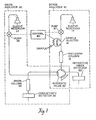
- Figure 1 illustrates schematically an ion chromatographic separation system according to this invention. Reference numerals therein correspond to elements described below.
- Boron analyzer 10 includes a chromatographic exclusion column 12.
- Column 12 is packed with an exclusion resin on which weakly ionized anions are resolved in the column. Strongly ionized anions pass through the column in void volume. Since boron, present as boric acid, is a weakly dissociated species, boron can be resolved in effluent from column 12. On the other hand, strongly ionized species, such as chloride, will pass through column 12 in void volume.
- Typical exclusion resins are sulfonated polymers, and a specific suitable material is a sulfonated copolymer of styrene and divinyl benzene.
- a first eluent contained in reservoir 14 is employed to elute the sample through column 12. Eluent is delivered from resevoir 14 by pump 16.
- the first eluent can be a strong acid such as sulfuric, nitric or phosphoric, or a weaker acid such as sulfonic, or salts thereof.
- Alkyl or aryl sulfonic acids e.g., octane sulfonic acid
- a sample is injected into the first eluent stream via automatic sample injector valve 18.
- Void volume and effluent from exclusion column 12 pass to automatic switching valve 20.
- Automatic valve 20 is preferably at least a six-port valve, the operation of which will be described further with reference to Figures 2-5.
- Void volume containing unretained anions to be further analyzed is directed into anion ' analyzer portion 30 of the system.
- Effluent from exclusion column 12 is directed by automatic valve 20 to refractive index detector 22. The presence and quantity of boron, resolved in exclusion column 12, are determined by detecting and monitoring the refractive index of effluent from column 1 2 by detector 22.
- Portion 30 includes a chromatographic anion column 32 packed with an anion exchange resin capable of resolving the strongly ionized anions.
- anion resins are typically polymeric resins having positively charged functional groups thereon.
- a specific example is a 10 um fully porous polymethyl methacrylate (PMMA) resin functionalized with alkyl substituted guaternary ammonium groups.
- Second eluent contained in reservoir 34 is delivered by pump 36 to automatic valve 20.
- Carboxylic acids or alkyl or aryl sulfonic acids, or salts of these, are examples of eluents suitable for use as a second eluent.
- automatic valve 20 directs second eluent from reservoir 34 to anion column 32.
- valve 20 directs second eluent to refractive index detector 22 while simultaneously directing void volume from exclusion column 12 to anion column 32 for anion analysis.
- the excluded anions in the original sample are resolved by the anion exchange resin in column 32 and the presence and quantity of these anions is determined by detecting and monitoring the conductivity of the solution by detector 38.
- the system is operated by microprocessor based controller 40, which may be included in one of the pumps.
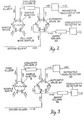
- Figure 2 illustrates the initial positions of automatic sample injector valve 18 and automatic switching valve 20, and the flow of first and second eluents, during the sample loading portion of the analysis.
- first eluent is directed through automatic sample injector valve 18 in a manner to bypass the sample loop and is passed directly to ion exclusion column 18 by automatic valve 20.
- Sample is directed into a suitable sample loop (e.g., 20 or 100 ul) within injector 18.
- Second eluent is directed by automatic valve 20 -directly to anion column 32.
- Figure 3 illustrates the positioning of sample injector 18 and automatic valve 20, and the flow of first and second eluents, during sample injection.
- the position of sample injector valve 18 has been switched so that first eluent is directed through the sample loop.
- the sample originally contained in the sample loop is injected into the eluent carrying it to ion exclusion column 12.
- the position of valve 20 remains the same as during sample loading.
- the sample is eluted with first eluent through ion exclusion column 12 and effluent from column 12 passes through automatic valve 20 to refractive index detector 22.
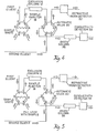
- Figure 4 illustrates the positioning of sample injector 18 and automatic valve 20, and the flow of first and second effluents, during the transfer of strongly ionized anions from the boron analyzer to the anion analyzer.
- the strongly ionized anions elute from the anion exclusion column in its void volume.
- valve 20 is switched to direct the void volume into anion analyzer 30.
- Valve 20 thus directs void volume from exclusion column 12 to anion column 32 for resolution of the additional anions.
- Valve 20 directs second eluent directly to the refractive index detector 22.
- a loop between ports 5 and 6 is used to allow the second eluent to flow directly to the refractive index detector preventing disturbances of the baseline.
- Figure 5 illustrates the positioning of valves 18 and 20, and the flow of first and second eluents, during analysis of strongly ionized anions.
- Automatic valve 20 is switched to its initial position reconnecting second eluent with anion column 32 and conductivity detector 38.
- Effluent from exclusion column 12 is allowed to pass again to refractive index detector 22.
- Sample injection valve 18 is also returned to its original position to load another sample for subsequent analysis.
- the invention is further specifically illustrated by following exemplification.
- the apparatus employed to analyze the sample is that illustrated in Figure 1 employing the following components.
- the ion exclusion column was a Fast Fruit Juice column marketed by Waters Chromatography Division, Millipore Corporation, Milford, MA. This column was a 7.8 mm x 15 cm steel chromatography column packed with a 50 A, 10 micron fully sulfonated resin.
- the anion exchange column was a Waters I.C. PAK anion column packed with a 10 micron PMMA resin (quaternary ammonium functional groups). The ion exchange capacity of the resin was 30 ⁇ 3 ueq/ml.
- the refractive index detector was a Waters 410 Differential Refractometer and the conductivity detector was a Waters 430 conductivity detector. Waters Models 510 and 590 solvent delivery systems were employed.
- the automatic sample injector valve and automatic switching valve were parts of the Waters Automated Valve Station (WAVS).
- the control system was a Waters 590 Programmable Module provided with the
- the reproducibility of boron analyses was tested by making 10 serial injections of three different solutions.
- the first was a solution of boric acid in water having 2,000 ppm boron.
- the second solution (natural pH) was a matrix made up simulating nuclear reactor water after a nuclear accident and formulated according to Nuclear Regulatory Commission regulations.
- This sample was prepared by dissolving potassium iodide, cesium nitrate, barium nitrate, lanthanum chloride, ammonium cerium nitrate, boric acid and lithium hydroxide in water to provide a sample containing the following anions:
- the third solution (high pH) was a matrix made up as the natural pH matrix but having its pH raised to 13 by the addition of sodium hydroxide.
- the latter solution is considered the worst case scenario according to the NRC regulations.
- 10mN sulfuric acid was employed as first eluent at a flow rate of 1.0 ml/min.
- a sample of 100 microliters (1:100 dilution) was injected.
- the second eluent was 3mM sodium octane sulfonate at a flow rate of 1 ml/min.
- the analysis time per sample was 5 minutes.
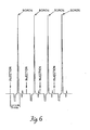
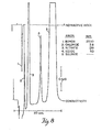
- the linearity of response in the boron analysis was studied by forming solutions containing 6, 60, 600, 1000, 2000, 3000, and 6000 ppm boron as boric acid in water. 1.25 mN sulfuric acid at a flow rate of 1.0 ml/min. was employed to elute 20 microliter samples. Data handling and processing were done on a Waters 840 system (integration method by areas). The results are shown plotted in Figure 7 indicating the outstanding linearity over a wide range of boron concentrations.
- the borate/gluconate eluent was prepared by initially formulating a concentrate containing 16g sodium gluconate, 18g boric acid, 25g sodium tetraborate.10H20, 125ml glycerine and reagent grade water to make one liter volume. The final eluent was prepared from 15ml borate/gluconate concentrate, 120ml acetonitrile, 865ml water (reagent grade) to form 1,000ml borate/gluconate eluent.
- the method and apparatus of this invention have been described in terms of the separation and quantitation of weakly ionized and strongly ionized anions present in the same liquid sample, other applications are possible with or without modifications to the apparatus or method.
- the system illustrated herein could also be used for on-line sample preparation. This would be useful, for example, in analyzing for inorganic anions in the presence of concentrated bases, such as sodium hydroxide, or in the presence of concentrated solutions of organic acids.
- the system with some modifications could be employed for the simultaneous analysis of alkali or alkaline earth cations in the presence of strongly ionized anions.
- modifications include the replacement of the exclusion column with a cation exchange column and the replacement of the refractive index detector with a conductivity detector to provide increased sensitivity.
- a suitable first eluent for use in the cation exchange column is octane sulfonic acid
- an example of a specific eluent for use in the anion column is sodium octane sulfonate.
- This invention is useful in analyzing liquid samples containing both strongly ionized and weakly ionized anions by ion chromatographic techniques. It is particularly useful in simultaneously analyzing water employed in a nuclear reactor after a nuclear accident has occurred for the presence of borate and chloride.
Landscapes
- Physics & Mathematics (AREA)
- Health & Medical Sciences (AREA)
- Life Sciences & Earth Sciences (AREA)
- Chemical & Material Sciences (AREA)
- Analytical Chemistry (AREA)
- Biochemistry (AREA)
- General Health & Medical Sciences (AREA)
- General Physics & Mathematics (AREA)
- Immunology (AREA)
- Pathology (AREA)
- Treatment Of Liquids With Adsorbents In General (AREA)
Applications Claiming Priority (2)
| Application Number | Priority Date | Filing Date | Title |
|---|---|---|---|
| US821154 | 1986-01-21 | ||
| US06/821,154 US4699718A (en) | 1986-01-21 | 1986-01-21 | Ion chromatography method and apparatus |
Publications (3)
| Publication Number | Publication Date |
|---|---|
| EP0230307A2 true EP0230307A2 (fr) | 1987-07-29 |
| EP0230307A3 EP0230307A3 (en) | 1988-04-27 |
| EP0230307B1 EP0230307B1 (fr) | 1992-04-01 |
Family
ID=25232655
Family Applications (1)
| Application Number | Title | Priority Date | Filing Date |
|---|---|---|---|
| EP87100712A Expired EP0230307B1 (fr) | 1986-01-21 | 1987-01-20 | Procédé et appareil de chromatographie d'ions |
Country Status (4)
| Country | Link |
|---|---|
| US (1) | US4699718A (fr) |
| EP (1) | EP0230307B1 (fr) |
| JP (1) | JPS62223668A (fr) |
| DE (1) | DE3777840D1 (fr) |
Cited By (2)
| Publication number | Priority date | Publication date | Assignee | Title |
|---|---|---|---|---|
| GB2223692A (en) * | 1988-09-16 | 1990-04-18 | Philips Nv | Liquid chromatography |
| EP0892267A1 (fr) * | 1997-07-15 | 1999-01-20 | Tosoh Corporation | Appareil de chromatographie en phase liquide avec vanne de commutation |
Families Citing this family (34)
| Publication number | Priority date | Publication date | Assignee | Title |
|---|---|---|---|---|
| US4814281A (en) * | 1986-01-07 | 1989-03-21 | Westinghouse Electric Corp. | Differential conductivity sulfate monitor |
| US4859342A (en) * | 1986-10-14 | 1989-08-22 | Suntory Limited | Process for industrially separating biopolymers |
| US4999105A (en) * | 1987-11-02 | 1991-03-12 | The Dow Chemical Company | Apparatus for membrane assisted liquid chromatography |
| US4775476A (en) * | 1987-11-02 | 1988-10-04 | The Dow Chemical Company | Method for membrane assisted liquid chromatography |
| JPH0721485B2 (ja) * | 1988-03-11 | 1995-03-08 | ダイソー株式会社 | 苛性アルカリ中塩化物イオンの流れ分析法 |
| US5132018A (en) * | 1988-05-20 | 1992-07-21 | Millipore Corporation | Isoconductive gradient ion chromatography |
| SE462303B (sv) * | 1988-10-27 | 1990-05-28 | Asea Atom Ab | Saett foer provberedning vid analys av partikulaera foereningar i ett floede av vatten |
| US5042293A (en) * | 1989-09-25 | 1991-08-27 | Heyde H Paul | Ion chromatography method for low concentrations |
| US4991428A (en) * | 1989-09-25 | 1991-02-12 | Heyde H Paul | Ion chromatography method for low concentrations |
| US5076097A (en) * | 1990-06-28 | 1991-12-31 | Tsi Incorporated | Method and apparatus for determining concentration of macromolecules and colloids in a liquid sample |
| CA2111695A1 (fr) * | 1991-06-26 | 1993-01-07 | Noubar B. Afeyan | Methode et appareil de detection des contaminants a l'etat de traces |
| US5133868A (en) * | 1991-10-07 | 1992-07-28 | Marathon Oil Comany | Identification of sulfonation by-products by ion chromatography |
| US5377234A (en) * | 1992-10-23 | 1994-12-27 | General Electric Company | Colloidal resin slurry recycle concentrating system of nuclear reactor coolant water |
| US5346622A (en) * | 1993-03-04 | 1994-09-13 | Hewlett-Packard Company | Hydrocarbon class separation and quantitation by split column effluent analysis |
| US5462660A (en) * | 1994-04-22 | 1995-10-31 | The United States Of America As Represented By The Secretary Of Agriculture | High performance liquid chromatography injection system for the simultaneous concentration and analysis of trace components |
| JP3512811B2 (ja) * | 1994-07-11 | 2004-03-31 | テクマー カンパニー | モジュール式バイアル自動サンプル装置 |
| US5948360A (en) | 1994-07-11 | 1999-09-07 | Tekmar Company | Autosampler with robot arm |
| ATE196949T1 (de) * | 1995-03-03 | 2000-10-15 | Alltech Associates Inc | Verfahren und vorrichtung zur elektrochemischen veränderung von chromatographiematerial |
| WO1997000969A1 (fr) * | 1995-06-20 | 1997-01-09 | Johannes Schumacher | Procede et dispositif de determination de l'activite d'enzymes dans des liquides ou de la concentration et/ou activite d'inhibiteurs dans des liquides |
| US5739422A (en) * | 1995-12-19 | 1998-04-14 | Dionex Corporation | Multicycle loop injection for trace analysis by ion chromatography apparatus and method |
| AU4450900A (en) | 1999-04-23 | 2000-11-10 | Advanced Bioanalytical Services, Inc. | High-throughput parallel liquid chromatography system |
| US6502448B1 (en) | 1999-09-07 | 2003-01-07 | Edward Rapkin | Chromatography detection system and method |
| US6962658B2 (en) * | 2003-05-20 | 2005-11-08 | Eksigent Technologies, Llc | Variable flow rate injector |
| JP4114076B2 (ja) * | 2004-02-17 | 2008-07-09 | 独立行政法人 日本原子力研究開発機構 | アクチノイド元素の分離方法 |
| US20070183928A1 (en) * | 2005-09-09 | 2007-08-09 | Eksigent Technologies, Llc | Variable flow rate system for column chromatography |
| JP2011141120A (ja) * | 2008-10-07 | 2011-07-21 | Arkray Inc | 液体クロマトグラフィ装置および液体クロマトグラフィ |
| KR101239884B1 (ko) | 2010-09-30 | 2013-03-06 | 한국원자력연구원 | 고온 수용액 내 불순물 감지방법 및 이를 위한 불순물 감지 장치 |
| EP2682168A1 (fr) | 2012-07-02 | 2014-01-08 | Millipore Corporation | Dispositif de tirage et métier à filer |
| JP6260719B2 (ja) * | 2014-12-15 | 2018-01-17 | 株式会社島津製作所 | 液体クロマトグラフ |
| CN104535518A (zh) * | 2015-01-20 | 2015-04-22 | 利穗科技(苏州)有限公司 | 一种新型ri在线检测层析和超滤系统 |
| JP6512630B2 (ja) * | 2015-02-26 | 2019-05-15 | オルガノ株式会社 | セレン及び/またはヒ素の濃縮方法及び分析方法並びに装置 |
| US11287403B2 (en) | 2016-01-07 | 2022-03-29 | Board Of Regents, The University Of Texas System | Ion chromatography system and methods utilizing a weak acid or weak base extraction device |
| CN111077264B (zh) * | 2020-01-03 | 2022-06-24 | 湖南金泰环保科技有限公司 | 实现单台离子色谱仪切换使用双系统的方法 |
| CN111735882B (zh) * | 2020-07-01 | 2022-05-20 | 沧州信联化工有限公司 | 一种高纯净tmah试剂离子色谱检测装置及其检测方法 |
Family Cites Families (8)
| Publication number | Priority date | Publication date | Assignee | Title |
|---|---|---|---|---|
| US3920397A (en) * | 1973-08-06 | 1975-11-18 | Dow Chemical Co | Apparatus and method for quantitative analysis of ionic species by liquid column chromatography |
| US3966596A (en) * | 1973-08-06 | 1976-06-29 | The Dow Chemical Company | High performance, cation-exchange chromatography on surface-sulfonated compositions |
| US3926559A (en) * | 1973-08-06 | 1975-12-16 | Dow Chemical Co | Method and apparatus for quantitative chromatographic analysis of cationic species |
| US4073725A (en) * | 1975-05-09 | 1978-02-14 | Hitachi, Ltd. | Method and apparatus for liquid chromatography under elevated pressure |
| US4251220A (en) * | 1978-10-30 | 1981-02-17 | Larson Thurston E | Apparatus for and method of determining high pressure, high temperature feedwater contaminants |
| US4314823A (en) * | 1979-03-05 | 1982-02-09 | Dionex Corporation | Combination apparatus and method for chromatographic separation and quantitative analysis of multiple ionic species |
| DE3173691D1 (en) * | 1980-03-13 | 1986-03-20 | Hitachi Ltd | Process for analyzing anions and process for treating radioactive liquid waste utilizing the same |
| JPS56162050A (en) * | 1980-04-22 | 1981-12-12 | Dionex Corp | Liquid chromatography and method of using ion condensation |
-
1986
- 1986-01-21 US US06/821,154 patent/US4699718A/en not_active Expired - Lifetime
-
1987
- 1987-01-20 DE DE8787100712T patent/DE3777840D1/de not_active Expired - Lifetime
- 1987-01-20 EP EP87100712A patent/EP0230307B1/fr not_active Expired
- 1987-01-21 JP JP62010141A patent/JPS62223668A/ja active Pending
Cited By (3)
| Publication number | Priority date | Publication date | Assignee | Title |
|---|---|---|---|---|
| GB2223692A (en) * | 1988-09-16 | 1990-04-18 | Philips Nv | Liquid chromatography |
| EP0892267A1 (fr) * | 1997-07-15 | 1999-01-20 | Tosoh Corporation | Appareil de chromatographie en phase liquide avec vanne de commutation |
| US5958227A (en) * | 1997-07-15 | 1999-09-28 | Tosoh Corporation | Liquid chromatograph apparatus with a switching valve |
Also Published As
| Publication number | Publication date |
|---|---|
| US4699718A (en) | 1987-10-13 |
| DE3777840D1 (de) | 1992-05-07 |
| EP0230307A3 (en) | 1988-04-27 |
| EP0230307B1 (fr) | 1992-04-01 |
| JPS62223668A (ja) | 1987-10-01 |
Similar Documents
| Publication | Publication Date | Title |
|---|---|---|
| US4699718A (en) | Ion chromatography method and apparatus | |
| Siriraks et al. | Chelation ion chromatography as a method for trace elemental analysis in complex environmental and biological samples | |
| US4314823A (en) | Combination apparatus and method for chromatographic separation and quantitative analysis of multiple ionic species | |
| Zhang et al. | Arsenic speciation in serum of uraemic patients based on liquid chromatography with hydride generation atomic absorption spectrometry and on-line UV photo-oxidation digestion | |
| Michalski | Recent development and applications of ion chromatography | |
| EP1924853B1 (fr) | Système de chromatographie ionique comportant un prétraitement d'échantillons et utilisant une seule pompe | |
| Bowman | Analysis of soil extracts for inorganic and organic tracer anions via high-performance liquid chromatography | |
| AU711415B2 (en) | Multi-cycle loop injection for trace analysis by ion chromatography apparatus and method | |
| US4272246A (en) | Method and apparatus for chromatographic quantitative analysis | |
| Cassidy et al. | Determination of metals in groundwaters by trace enrichment and liquid chromatography | |
| Michalski | Principles and applications of ion chromatography | |
| Michalski et al. | Ion chromatography as a part of green analytical chemistry | |
| DiNunzio et al. | Donnan dialysis preconcentration for ion chromatography | |
| Kerr et al. | Determination of uranium in natural groundwaters using high-performance liquid chromatography | |
| Jones et al. | Automated dual column coupled system for simultaneous determination of carboxylic acids and inorganic anions | |
| EP0202437A2 (fr) | Chromatographie à échange d'ions avec détection photométrique indirecte | |
| EP0186037A2 (fr) | Analyse indépendante d'anions et de cations utilisant la chromatographie photométrique indirecte | |
| Toofan et al. | Preconcentration determination of inorganic anions and organic acids in power plant waters separation optimization through control of column capacity and selectivity | |
| Onuska et al. | Isotachophoresis: Trials, tribulations, and trends in trace analysis of organic and inorganic pollutants | |
| Lemos et al. | An online preconcentration system for the determination of uranium in water and effluent samples | |
| Dasgupta | On the ion chromatographic determination of S (IV) | |
| Fitchett | Analysis of rain by ion chromatography | |
| Tabatabai et al. | Ion chromatography | |
| Takeuchi et al. | Indirect photometric detection of monovalent cations via postsuppressor ion replacement in microcolumn ion chromatography | |
| Cassidy et al. | Liquid chromatographic determination of the number of fissions in uranium/aluminium nuclear fuels |
Legal Events
| Date | Code | Title | Description |
|---|---|---|---|
| PUAI | Public reference made under article 153(3) epc to a published international application that has entered the european phase |
Free format text: ORIGINAL CODE: 0009012 |
|
| AK | Designated contracting states |
Kind code of ref document: A2 Designated state(s): DE FR GB IT NL SE |
|
| PUAL | Search report despatched |
Free format text: ORIGINAL CODE: 0009013 |
|
| AK | Designated contracting states |
Kind code of ref document: A3 Designated state(s): DE FR GB IT NL SE |
|
| 17P | Request for examination filed |
Effective date: 19880614 |
|
| 17Q | First examination report despatched |
Effective date: 19900528 |
|
| RBV | Designated contracting states (corrected) |
Designated state(s): DE FR GB IT |
|
| ITTA | It: last paid annual fee | ||
| GRAA | (expected) grant |
Free format text: ORIGINAL CODE: 0009210 |
|
| AK | Designated contracting states |
Kind code of ref document: B1 Designated state(s): DE FR GB IT |
|
| ET | Fr: translation filed | ||
| REF | Corresponds to: |
Ref document number: 3777840 Country of ref document: DE Date of ref document: 19920507 |
|
| ITF | It: translation for a ep patent filed | ||
| PGFP | Annual fee paid to national office [announced via postgrant information from national office to epo] |
Ref country code: FR Payment date: 19921210 Year of fee payment: 7 |
|
| PGFP | Annual fee paid to national office [announced via postgrant information from national office to epo] |
Ref country code: DE Payment date: 19921211 Year of fee payment: 7 |
|
| PGFP | Annual fee paid to national office [announced via postgrant information from national office to epo] |
Ref country code: GB Payment date: 19921231 Year of fee payment: 7 |
|
| PLBE | No opposition filed within time limit |
Free format text: ORIGINAL CODE: 0009261 |
|
| STAA | Information on the status of an ep patent application or granted ep patent |
Free format text: STATUS: NO OPPOSITION FILED WITHIN TIME LIMIT |
|
| 26N | No opposition filed | ||
| PG25 | Lapsed in a contracting state [announced via postgrant information from national office to epo] |
Ref country code: GB Effective date: 19940120 |
|
| REG | Reference to a national code |
Ref country code: GB Ref legal event code: 732E |
|
| REG | Reference to a national code |
Ref country code: FR Ref legal event code: TP |
|
| GBPC | Gb: european patent ceased through non-payment of renewal fee |
Effective date: 19940120 |
|
| PG25 | Lapsed in a contracting state [announced via postgrant information from national office to epo] |
Ref country code: FR Effective date: 19940930 |
|
| PG25 | Lapsed in a contracting state [announced via postgrant information from national office to epo] |
Ref country code: DE Effective date: 19941001 |
|
| REG | Reference to a national code |
Ref country code: FR Ref legal event code: ST |
|
| PG25 | Lapsed in a contracting state [announced via postgrant information from national office to epo] |
Ref country code: IT Free format text: LAPSE BECAUSE OF NON-PAYMENT OF DUE FEES Effective date: 20050120 |