EP0230323A2 - Verschlusszähler - Google Patents
Verschlusszähler Download PDFInfo
- Publication number
- EP0230323A2 EP0230323A2 EP87100912A EP87100912A EP0230323A2 EP 0230323 A2 EP0230323 A2 EP 0230323A2 EP 87100912 A EP87100912 A EP 87100912A EP 87100912 A EP87100912 A EP 87100912A EP 0230323 A2 EP0230323 A2 EP 0230323A2
- Authority
- EP
- European Patent Office
- Prior art keywords
- housing
- counting unit
- display unit
- closure
- rotation
- Prior art date
- Legal status (The legal status is an assumption and is not a legal conclusion. Google has not performed a legal analysis and makes no representation as to the accuracy of the status listed.)
- Granted
Links
Images
Classifications
-
- G—PHYSICS
- G06—COMPUTING OR CALCULATING; COUNTING
- G06M—COUNTING MECHANISMS; COUNTING OF OBJECTS NOT OTHERWISE PROVIDED FOR
- G06M1/00—Design features of general application
- G06M1/08—Design features of general application for actuating the drive
- G06M1/083—Design features of general application for actuating the drive by mechanical means
Definitions
- the invention relates to a closure counter for counting how many times a screw cap closure has been closed and opened, said closure counter being back in its initial position after N closing and opening operations.
- the closure counter is to require no additional manipulation, i.e. the closure counter is to be actuated automatically when the closure cap is opened and closed.
- the closure counter has an open-bottomed housing and a likewise open-bottomed cap-shaped counting unit arranged in the housing and rotatable about its longitudinal axis, said rotary motion being limited to a fraction 1/N of a full rotation, and a display unit arranged for rotation about the longitudinal axis of the counting unit, said rotation of the display unit relative to the counting unit being allowed by a ratchet in only one direction, the click motion likewise being the fraction 1/N of a full rotation, and there is sliding fit between the housing and the display unit.
- the housing, the counting unit and the display unit are suitably of cylindrical configuration, and the display unit is provided on the upper end of the counting unit having lesser external diameter, so that the display unit and the counting unit have substantially equal external diameters.
- the external diameter of the display unit is somewhat wider, since there is sliding fit between the display unit and the inner side of the housing, while the counting unit can rotate within the housing with more clearance.
- the counting unit can rotate within the housing through only a limited angle which is equal to the Nth fraction of a full rotation.
- This limitation can be attained by a pin projecting from the inner housing wall and engaging a groove in the outer side of the counting unit; said pin can also be formed on the outside of the counting unit and said groove in the inside of the housing. It is also possible to provide at the lower rim of the housing inside projections engaging the lower rim of the counting unit. Between the projections and the recesses there is a clearance in peripheral direction which corresponds to the Nth part of a full rotation. Owing to said relatively wide clearance there are generally provided only two or three recesses and projections.
- the display unit is connected to the counting unit by way of a ratchet so that, upon rotation in one direction, the counting unit carries the display unit along, while upon rotation in the opposite direction the display unit is not carried along, i.e. it does not co-rotate.
- a ratchet For this purpose preferably sawtooth-like teeth jut out at about half the height of the display unit, and at the lower rim of the display unit one or more pawls are provided.
- the click motion i.e. the spacing of the teeth, likewise corresponds to the Nth part of the circle periphery, so that altogether N teeth are provided.
- Locking can be effected either upon right-hand or left-hand rotation. Depending on the lock ing direction, the display unit is rotated through the Nth part of a full rotation relative to the housing either upon opening or closing of the screw cap closure.
- the teeth can be provided also at the display unit and the pawl at the counting unit. It is merely essential that the display unit and the counting unit cooperate like a ratchet, i.e. that upon rotation in one direction they are locked together, while in the other direction they are free.
- the sliding fit can be tightened by the insertion of a small spring along a secant at the head portion of the display unit so that the spring slightly extends beyond the cylinder periphery.
- the counting unit is cap-shaped so that it is hollow inside.
- the cavity can be formed such that it fits onto the screw cap closure of a container and is positively or non-positively engaged therewith.
- the counting unit itself can form the screw cap closure, and to this end it can be provided with threads or other closing means on the cavity interior.
- the closure counter operates as follows: To open the closure, the housing is turned counterclockwise relative to the container, as usual. Owing to the sliding fit, the housing carries the display unit along, while the counting unit is carried along only after one Nth rotation.
- the ratchet is to be so designed that in counterclockweise direction the display unit is freely movable relative to the counting unit.
- the cap of the screw closure is opened in the usual way. Since the display unit does not rotate relative to the housing, the display remains unchanged.
- the display consists of N indicia of equal angular width on the outside of the display unit, one at a time being visible through a window in the cylinder wall of the housing which is in register therewith.
- the fixedly positioned top of the housing may be provided with a window. In that case one section each in the top area of the display unit becomes visible.
- the closure counter is placed in the usual way on the container opening and is turned clockwise.
- the housing carries along the counting unit only after one Nth rotation. Since in clockwise direction the rotation of the display unit relative to the counting unit is locked, also the display unit is carried along only after one Nth rotation, i.e. in the window of the housing the next indicium area appears. The housing is then rotated further in clockwise direction until the container is closed.
- counting can begin with any desired display area.
- the display areas can be switched by turning the housing back and forth relative to the counting unit.
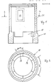
- the housing 10 is, on the whole, of cylindrical shape and is open at the bottom, while on top it is closed by a cover 30.
- the cover 30 is detachable for assembly purposes.
- the cover 30 can also be integral with the cylinder wall 31.
- At the lower end of the inside of the cylinder wall 31 three projections 19 are provided which resemble merlons extending each around 60° of the circle circumference and spaced apart an equal angular width.
- the lower rim of the cylinder wall 31 is thickened somewhat in outward and inward direction.
- the inwardly facing thickened portion corresponds to the thickness of the projections 19.
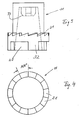
- Figs. 3, 4 and 5 show the counting unit 11. It has the shape of a cap, i.e. an open-bottomed cylinder.
- the cylindrical outer surface widens downwardly in a step at about 1/3 of its height, said enlargement being required to accommodate teeth 21 of a ratchet 14.
- Below the teeth 21 there are three niche-like recesses 20 extending each over an angle of about 90° leaving ribs 32 of an angular width of about 30°.
- the niche-like recesses 20 in the assembled closure counter engage, in the manner of a denture clutch, the projections 19 on the housing inside 10 permitting one 14th rotation (rotation through 25.71°) between the housing 10 and the counting unit 11.
- the teeth 21 have sawtooth shape.
- Fig. 4 shows the counting unit from top with the tooth tips visible.
- Fig. 5 shows the counting unit from the bottom.
- the hollow inside of the counting unit 11 is designed so that it can grip a frustoconical closure cap having a crater-shaped depression at the blunt top.
- the hollow inside has a cruciform projection 33 at the upper end thereof which extends downwardly with chamfered edges.
- the cruciform projection 33 extends into the crater-shaped depression of the screw cap closure.
- the external diameter of the counting unit 11 in the region below the toothed ring is somewhat smaller than the inner diameter of the housing 10 so that the counting unit 11 is freely rotatable within the housing 10.
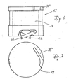
- Figs. 6 and 7 show the display unit 13. It is likewise shaped like an open-bottomed hollow cylinder.
- the external diameter of the display unit 13 is matched to the inner diameter of the housing 10 such that there is sliding fit between the two units, i.e. that the display unit 13, though being not freely movable within the housing 10, can be turned with only slight force within the housing 10.
- Spaced from the upper and lower ends the display unit 13 has a display region 34 of somewhat reduced outer diameter. Said region carries the display areas extending each over an angular width of 25.71° and bearing the indicia. In the present case these are the weekdays, each weekday appearing two consecutive times on differently colored areas.
- the reduction of the outer diameter in the display region 34 is to prevent the indicia from contacting the inner side of the housing 10 and thus from being chafed away.
- Two pawls 22 are provided at the lower rim of the display unit 13 in diametrically opposed relation forming, together with the teeth 21 of the counting unit 11, the ratchet 14.
- the pawls 22 resiliently extend beyond the lower rim of the display unit 13 so that they resiliently bear against the teeth 21.
- a small spring 35 in the form of a stiff steel wire can be inserted, as shown in Fig. 7, urging against the inside of the housing 10 and making sliding fit of steady torque.
- the hollow inside of the display unit 13 has a somewhat larger inner diameter than the outer diameter in the upper region of the counting unit 11.
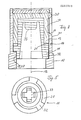
- Fig. 8 shows through the assembled closure counter.
- the closure counter is assembled such that the counting unit 11 is introduced into the housing 10 from above in such a way that the niche-like recesses 20 of the counting unit 11 receive the projections 19 in the housing 10.
- the display unit 13 is then inserted into the annular space remaining between the counting unit 11 and the housing 10.
- the housing top is then closed by impression of the cover 30, whereafter the closure counter is complete and can be placed on the screw cap of a container.
- the closure counter does not require any additional manipulation.
- the counting unit 11 advances by14th of a full rotation relative to the housing 10.
- the counting unit 11 takes along the display unit 13 only when rotated in one direction, namely when the screw cap closure is closed and the housing is turned clockwise while the counting unit 1 turns counterclockwise through a 14th of one full rotation relative to the housing thereby carrying along the display unit 13.
- the housing is turned in the opposite direction, e.g. when the screw cap closure is opened, the counting unit rotates clockwise relative to the housing 10.
- the display unit corotates with the housing 10, and the pawls 22 slide over one tooth 21 and click behind said tooth 21.
- the number of teeth 21 is thus equal to the number of the display areas, and each tooth 21 extends through25.71°, i.e. one 14th of a full circle, just like each display area.
- the number of display areas, and thus also the number of teeth 21, can be selected according to requirements.
- the configuration of the hollow interior of the counting unit 11 can be adapted to the requirements of the individual case, i.e. to the external shape of the screw cap closure.
- the counting unit 11 itself can form the screw cap closure and, to this end, can be provided with threads in the lower portion of the interior cooperating with the external threads provided around the opening of the container to be closed.
- the housing 10, the counting unit 11, and the display unit 13 can be made of any desired material. Suitably they are injection molded from synthetic resin.
Landscapes
- General Physics & Mathematics (AREA)
- Engineering & Computer Science (AREA)
- Theoretical Computer Science (AREA)
- Physics & Mathematics (AREA)
- Closures For Containers (AREA)
- Indication In Cameras, And Counting Of Exposures (AREA)
- Extrusion Moulding Of Plastics Or The Like (AREA)
- Vehicle Body Suspensions (AREA)
- Supplying Of Containers To The Packaging Station (AREA)
- Burglar Alarm Systems (AREA)
- Displays For Variable Information Using Movable Means (AREA)
- Transforming Light Signals Into Electric Signals (AREA)
- Details Of Measuring And Other Instruments (AREA)
- Exposure Control For Cameras (AREA)
- Infusion, Injection, And Reservoir Apparatuses (AREA)
- Investigating Or Analysing Materials By The Use Of Chemical Reactions (AREA)
- Details Of Rigid Or Semi-Rigid Containers (AREA)
- Liquid Crystal Substances (AREA)
Priority Applications (1)
| Application Number | Priority Date | Filing Date | Title |
|---|---|---|---|
| AT87100912T ATE88030T1 (de) | 1986-01-24 | 1987-01-23 | Verschlusszaehler. |
Applications Claiming Priority (2)
| Application Number | Priority Date | Filing Date | Title |
|---|---|---|---|
| DE19863602119 DE3602119A1 (de) | 1986-01-24 | 1986-01-24 | Verschlusszaehler |
| DE3602119 | 1986-01-24 |
Publications (3)
| Publication Number | Publication Date |
|---|---|
| EP0230323A2 true EP0230323A2 (de) | 1987-07-29 |
| EP0230323A3 EP0230323A3 (en) | 1989-06-14 |
| EP0230323B1 EP0230323B1 (de) | 1993-04-07 |
Family
ID=6292539
Family Applications (1)
| Application Number | Title | Priority Date | Filing Date |
|---|---|---|---|
| EP87100912A Expired - Lifetime EP0230323B1 (de) | 1986-01-24 | 1987-01-23 | Verschlusszähler |
Country Status (9)
| Country | Link |
|---|---|
| US (1) | US4792664A (de) |
| EP (1) | EP0230323B1 (de) |
| JP (1) | JPS62235082A (de) |
| AT (1) | ATE88030T1 (de) |
| CA (1) | CA1293958C (de) |
| DE (2) | DE3602119A1 (de) |
| DK (1) | DK170265B1 (de) |
| ES (1) | ES2040704T3 (de) |
| FI (1) | FI91567C (de) |
Cited By (3)
| Publication number | Priority date | Publication date | Assignee | Title |
|---|---|---|---|---|
| US5009338A (en) * | 1989-02-03 | 1991-04-23 | Senetics Corporation | Indicator cap for a medicine bottle |
| US5261548A (en) * | 1989-02-03 | 1993-11-16 | Senetics, Inc. | Indicator cap for use with threaded or bayonet lug container |
| US5299701A (en) * | 1989-02-03 | 1994-04-05 | Senetics, Inc. | Indicator cap |
Families Citing this family (26)
| Publication number | Priority date | Publication date | Assignee | Title |
|---|---|---|---|---|
| US5421482A (en) * | 1989-02-03 | 1995-06-06 | Senetics, Inc. | Indicator device responsive to axial force |
| DE4027669A1 (de) * | 1990-08-31 | 1992-03-05 | Pfeiffer Erich Gmbh & Co Kg | Austragvorrichtung fuer medien |
| DE59107710D1 (de) * | 1990-08-31 | 1996-05-30 | Pfeiffer Erich Gmbh & Co Kg | Austragvorrichtung für Medien |
| DE4030530A1 (de) * | 1990-09-27 | 1992-04-02 | Pfeiffer Erich Gmbh & Co Kg | Austragvorrichtung fuer medien |
| JP4423457B2 (ja) | 1998-01-16 | 2010-03-03 | トルーデル メディカル インターナショナル | ディスペンサおよび投与装置用表示装置 |
| US6142339A (en) | 1998-01-16 | 2000-11-07 | 1263152 Ontario Inc. | Aerosol dispensing device |
| US5931302A (en) * | 1998-02-09 | 1999-08-03 | Innovative Premiums Inc. | Pellet dispenser |
| US6082358A (en) | 1998-05-05 | 2000-07-04 | 1263152 Ontario Inc. | Indicating device for aerosol container |
| US6729330B2 (en) | 1998-05-05 | 2004-05-04 | Trudell Medical International | Indicating device for aerosol container |
| US6336453B1 (en) | 1999-04-30 | 2002-01-08 | Trudell Medical International | Indicating device for aerosol container |
| US6745760B2 (en) | 2001-05-15 | 2004-06-08 | Trudell Medical International | Medicament applicator |
| US7004164B2 (en) | 2002-03-21 | 2006-02-28 | Trudell Medical International | Indicating device for aerosol container |
| US7621273B2 (en) | 2003-10-28 | 2009-11-24 | Trudell Medical International | Indicating device with warning dosage indicator |
| US7100530B2 (en) | 2003-12-15 | 2006-09-05 | Trudell Medical International, Inc. | Dose indicating device |
| US7543582B2 (en) | 2004-09-20 | 2009-06-09 | Trudell Medical International | Dose indicating device with display elements attached to container |
| US7886934B2 (en) | 2005-01-20 | 2011-02-15 | Trudell Medical International | Dispensing device |
| US8141550B2 (en) | 2006-08-01 | 2012-03-27 | Trudell Medical International | Dispensing device |
| US20090032547A1 (en) * | 2007-07-31 | 2009-02-05 | Theresa Litherland | Three button actuated pill holder/dispenser |
| US8082873B2 (en) | 2008-05-05 | 2011-12-27 | Trudell Medical International | Drive mechanism for an indicating device |
| US8181591B1 (en) | 2008-05-23 | 2012-05-22 | Trudell Medical International | Domed actuator for indicating device |
| CA2683353C (en) | 2008-10-22 | 2015-12-15 | Trudell Medical International | Modular aerosol delivery system |
| EP2917129B1 (de) | 2012-11-10 | 2017-01-04 | Kraft Foods Group Brands LLC | Behälter mit abnehmbarer messkappe |
| CN106610449B (zh) * | 2015-10-23 | 2023-03-24 | 福建三洲电力科技有限公司 | 一种避雷器用二进制雷击计数装置 |
| EP3199288B8 (de) * | 2016-01-28 | 2024-05-29 | Böllhoff Verbindungstechnik GmbH | Elementzuführeinrichtung eines setz-schweiss-geräts, ein setz-schweiss-gerät sowie ein verbindungsverfahren in form eines mechanisch-thermischen setz-schweiss-prozesses |
| US20190161254A1 (en) * | 2017-11-29 | 2019-05-30 | Cory J. Wilson | Child-resistant cap |
| CA3001033A1 (en) * | 2018-04-11 | 2019-10-11 | Dwaine Mcneil | System and method for transporting drugs |
Family Cites Families (13)
| Publication number | Priority date | Publication date | Assignee | Title |
|---|---|---|---|---|
| US3279651A (en) * | 1965-02-08 | 1966-10-18 | Gordon J Thompson | Article dispenser having rupturable cells and means to eject articles therefrom |
| US3385421A (en) * | 1967-01-05 | 1968-05-28 | Ortho Pharma Corp | Strip dispensing device |
| DK119125B (da) * | 1967-11-01 | 1970-11-16 | Novo Terapeutisk Labor As | Tabletbeholder med datoindikering. |
| US4011829A (en) * | 1974-10-01 | 1977-03-15 | Doris Beryl Wachsmann | Closure having indicating means |
| US4223801A (en) * | 1978-01-26 | 1980-09-23 | Carlson Torsten S | Automatic periodic drug dispensing system |
| CA1085352A (en) * | 1978-09-19 | 1980-09-09 | William Rossmo | Medication dispenser |
| US4220247A (en) * | 1979-04-04 | 1980-09-02 | Kramer Steven G | Closure members |
| US4365722A (en) * | 1981-06-26 | 1982-12-28 | Kramer Steven G | Reminder closure |
| DE3210361A1 (de) * | 1982-03-20 | 1983-10-20 | Gotthard 8230 Bad Reichenhall Neugebauer | Kindersichere arzneimittelpackung |
| GB2116153B (en) * | 1982-11-01 | 1984-04-26 | Esther B Lyss | Pill dispenser with sequential dispensing and indicating cap |
| GB8308231D0 (en) * | 1983-03-25 | 1983-05-05 | Vee Tek Ltd | Bottles and caps |
| US4528933A (en) * | 1983-05-11 | 1985-07-16 | Robert Allen | Container with indicating closure |
| GB2179778A (en) * | 1985-08-29 | 1987-03-11 | Alternate Resources Limited | Indicator device |
-
1986
- 1986-01-24 DE DE19863602119 patent/DE3602119A1/de not_active Ceased
- 1986-12-24 US US06/946,263 patent/US4792664A/en not_active Expired - Fee Related
-
1987
- 1987-01-16 FI FI870171A patent/FI91567C/fi not_active IP Right Cessation
- 1987-01-22 CA CA000527937A patent/CA1293958C/en not_active Expired - Lifetime
- 1987-01-23 ES ES198787100912T patent/ES2040704T3/es not_active Expired - Lifetime
- 1987-01-23 EP EP87100912A patent/EP0230323B1/de not_active Expired - Lifetime
- 1987-01-23 DK DK037887A patent/DK170265B1/da not_active IP Right Cessation
- 1987-01-23 DE DE87100912T patent/DE3785224T2/de not_active Expired - Fee Related
- 1987-01-23 AT AT87100912T patent/ATE88030T1/de not_active IP Right Cessation
- 1987-01-24 JP JP62013354A patent/JPS62235082A/ja active Pending
Cited By (3)
| Publication number | Priority date | Publication date | Assignee | Title |
|---|---|---|---|---|
| US5009338A (en) * | 1989-02-03 | 1991-04-23 | Senetics Corporation | Indicator cap for a medicine bottle |
| US5261548A (en) * | 1989-02-03 | 1993-11-16 | Senetics, Inc. | Indicator cap for use with threaded or bayonet lug container |
| US5299701A (en) * | 1989-02-03 | 1994-04-05 | Senetics, Inc. | Indicator cap |
Also Published As
| Publication number | Publication date |
|---|---|
| ES2040704T3 (es) | 1993-11-01 |
| DE3785224D1 (de) | 1993-05-13 |
| FI91567C (fi) | 1994-07-11 |
| FI91567B (fi) | 1994-03-31 |
| EP0230323B1 (de) | 1993-04-07 |
| ATE88030T1 (de) | 1993-04-15 |
| EP0230323A3 (en) | 1989-06-14 |
| JPS62235082A (ja) | 1987-10-15 |
| US4792664A (en) | 1988-12-20 |
| DK37887A (da) | 1987-07-25 |
| DE3785224T2 (de) | 1993-11-04 |
| DK37887D0 (da) | 1987-01-23 |
| DK170265B1 (da) | 1995-07-17 |
| DE3602119A1 (de) | 1987-07-30 |
| CA1293958C (en) | 1992-01-07 |
| FI870171A0 (fi) | 1987-01-16 |
| FI870171A7 (fi) | 1987-07-25 |
Similar Documents
| Publication | Publication Date | Title |
|---|---|---|
| US4792664A (en) | Closure counter | |
| US4749093A (en) | Child-resistant medication reminder | |
| US4489834A (en) | Counting cap for medicine bottles | |
| US4666051A (en) | In cap medication reminder | |
| US5261548A (en) | Indicator cap for use with threaded or bayonet lug container | |
| US5520307A (en) | Dispensing top for pill case | |
| US5299701A (en) | Indicator cap | |
| US4528933A (en) | Container with indicating closure | |
| US5421482A (en) | Indicator device responsive to axial force | |
| US4011829A (en) | Closure having indicating means | |
| EP0381494B1 (de) | Behälterkappe mit Anzeigevorrichtung | |
| US5799651A (en) | Indicator device responsive to axial force | |
| US5718355A (en) | Indicator device responsive to axial force for use with inhaler | |
| US4920912A (en) | Time dial for pharmaceutical containers | |
| US5082129A (en) | Snap-lock for screw-cap container | |
| US5242067A (en) | Adaptor for indicator device | |
| US5586087A (en) | Container | |
| US5184739A (en) | Child resistant reminder closure | |
| US4220247A (en) | Closure members | |
| US5520296A (en) | Virtual hinge | |
| US4562933A (en) | Bottle having cap with safety feature and counter | |
| US7000791B2 (en) | Vial closure with indicator | |
| GB2179778A (en) | Indicator device | |
| US5702013A (en) | Virtual hinge | |
| US11932469B2 (en) | Dispensing system cap and cap system |
Legal Events
| Date | Code | Title | Description |
|---|---|---|---|
| PUAI | Public reference made under article 153(3) epc to a published international application that has entered the european phase |
Free format text: ORIGINAL CODE: 0009012 |
|
| AK | Designated contracting states |
Kind code of ref document: A2 Designated state(s): AT BE CH DE ES FR GB IT LI LU NL SE |
|
| ITCL | It: translation for ep claims filed |
Representative=s name: SOCIETA' ITALIANA BREVETTI S.P.A. |
|
| PUAL | Search report despatched |
Free format text: ORIGINAL CODE: 0009013 |
|
| AK | Designated contracting states |
Kind code of ref document: A3 Designated state(s): AT BE CH DE ES FR GB IT LI LU NL SE |
|
| 17P | Request for examination filed |
Effective date: 19890808 |
|
| 17Q | First examination report despatched |
Effective date: 19910402 |
|
| ITF | It: translation for a ep patent filed | ||
| GRAA | (expected) grant |
Free format text: ORIGINAL CODE: 0009210 |
|
| AK | Designated contracting states |
Kind code of ref document: B1 Designated state(s): AT BE CH DE ES FR GB IT LI LU NL SE |
|
| REF | Corresponds to: |
Ref document number: 88030 Country of ref document: AT Date of ref document: 19930415 Kind code of ref document: T |
|
| REF | Corresponds to: |
Ref document number: 3785224 Country of ref document: DE Date of ref document: 19930513 |
|
| ET | Fr: translation filed | ||
| REG | Reference to a national code |
Ref country code: ES Ref legal event code: FG2A Ref document number: 2040704 Country of ref document: ES Kind code of ref document: T3 |
|
| PLBE | No opposition filed within time limit |
Free format text: ORIGINAL CODE: 0009261 |
|
| STAA | Information on the status of an ep patent application or granted ep patent |
Free format text: STATUS: NO OPPOSITION FILED WITHIN TIME LIMIT |
|
| EPTA | Lu: last paid annual fee | ||
| 26N | No opposition filed | ||
| EAL | Se: european patent in force in sweden |
Ref document number: 87100912.2 |
|
| ITTA | It: last paid annual fee | ||
| PGFP | Annual fee paid to national office [announced via postgrant information from national office to epo] |
Ref country code: SE Payment date: 20000103 Year of fee payment: 14 Ref country code: AT Payment date: 20000103 Year of fee payment: 14 |
|
| PGFP | Annual fee paid to national office [announced via postgrant information from national office to epo] |
Ref country code: CH Payment date: 20000106 Year of fee payment: 14 |
|
| PGFP | Annual fee paid to national office [announced via postgrant information from national office to epo] |
Ref country code: NL Payment date: 20000110 Year of fee payment: 14 |
|
| PGFP | Annual fee paid to national office [announced via postgrant information from national office to epo] |
Ref country code: LU Payment date: 20000113 Year of fee payment: 14 |
|
| PGFP | Annual fee paid to national office [announced via postgrant information from national office to epo] |
Ref country code: BE Payment date: 20000125 Year of fee payment: 14 |
|
| PGFP | Annual fee paid to national office [announced via postgrant information from national office to epo] |
Ref country code: GB Payment date: 20001222 Year of fee payment: 15 |
|
| PGFP | Annual fee paid to national office [announced via postgrant information from national office to epo] |
Ref country code: FR Payment date: 20010102 Year of fee payment: 15 |
|
| PGFP | Annual fee paid to national office [announced via postgrant information from national office to epo] |
Ref country code: DE Payment date: 20010103 Year of fee payment: 15 |
|
| PG25 | Lapsed in a contracting state [announced via postgrant information from national office to epo] |
Ref country code: LU Free format text: LAPSE BECAUSE OF NON-PAYMENT OF DUE FEES Effective date: 20010123 Ref country code: AT Free format text: LAPSE BECAUSE OF NON-PAYMENT OF DUE FEES Effective date: 20010123 |
|
| PG25 | Lapsed in a contracting state [announced via postgrant information from national office to epo] |
Ref country code: SE Free format text: LAPSE BECAUSE OF NON-PAYMENT OF DUE FEES Effective date: 20010124 |
|
| PG25 | Lapsed in a contracting state [announced via postgrant information from national office to epo] |
Ref country code: LI Free format text: LAPSE BECAUSE OF NON-PAYMENT OF DUE FEES Effective date: 20010131 Ref country code: CH Free format text: LAPSE BECAUSE OF NON-PAYMENT OF DUE FEES Effective date: 20010131 Ref country code: BE Free format text: LAPSE BECAUSE OF NON-PAYMENT OF DUE FEES Effective date: 20010131 |
|
| PGFP | Annual fee paid to national office [announced via postgrant information from national office to epo] |
Ref country code: ES Payment date: 20010208 Year of fee payment: 15 |
|
| BERE | Be: lapsed |
Owner name: CHIBRET PHARMAZEUTISCHE G.M.B.H. Effective date: 20010131 |
|
| PG25 | Lapsed in a contracting state [announced via postgrant information from national office to epo] |
Ref country code: NL Free format text: LAPSE BECAUSE OF NON-PAYMENT OF DUE FEES Effective date: 20010801 |
|
| EUG | Se: european patent has lapsed |
Ref document number: 87100912.2 |
|
| REG | Reference to a national code |
Ref country code: CH Ref legal event code: PL |
|
| NLV4 | Nl: lapsed or anulled due to non-payment of the annual fee |
Effective date: 20010801 |
|
| REG | Reference to a national code |
Ref country code: GB Ref legal event code: IF02 |
|
| PG25 | Lapsed in a contracting state [announced via postgrant information from national office to epo] |
Ref country code: GB Free format text: LAPSE BECAUSE OF NON-PAYMENT OF DUE FEES Effective date: 20020123 |
|
| PG25 | Lapsed in a contracting state [announced via postgrant information from national office to epo] |
Ref country code: ES Free format text: LAPSE BECAUSE OF NON-PAYMENT OF DUE FEES Effective date: 20020124 |
|
| PG25 | Lapsed in a contracting state [announced via postgrant information from national office to epo] |
Ref country code: DE Free format text: LAPSE BECAUSE OF NON-PAYMENT OF DUE FEES Effective date: 20020801 |
|
| GBPC | Gb: european patent ceased through non-payment of renewal fee |
Effective date: 20020123 |
|
| PG25 | Lapsed in a contracting state [announced via postgrant information from national office to epo] |
Ref country code: FR Free format text: LAPSE BECAUSE OF NON-PAYMENT OF DUE FEES Effective date: 20020930 |
|
| REG | Reference to a national code |
Ref country code: FR Ref legal event code: ST |
|
| REG | Reference to a national code |
Ref country code: ES Ref legal event code: FD2A Effective date: 20030922 |
|
| PG25 | Lapsed in a contracting state [announced via postgrant information from national office to epo] |
Ref country code: IT Free format text: LAPSE BECAUSE OF NON-PAYMENT OF DUE FEES;WARNING: LAPSES OF ITALIAN PATENTS WITH EFFECTIVE DATE BEFORE 2007 MAY HAVE OCCURRED AT ANY TIME BEFORE 2007. THE CORRECT EFFECTIVE DATE MAY BE DIFFERENT FROM THE ONE RECORDED. Effective date: 20050123 |