EP0230361A2 - Anordnung und Verfahren zur Helligkeitsregelung in einem elektronischen Drucker - Google Patents
Anordnung und Verfahren zur Helligkeitsregelung in einem elektronischen Drucker Download PDFInfo
- Publication number
- EP0230361A2 EP0230361A2 EP87300176A EP87300176A EP0230361A2 EP 0230361 A2 EP0230361 A2 EP 0230361A2 EP 87300176 A EP87300176 A EP 87300176A EP 87300176 A EP87300176 A EP 87300176A EP 0230361 A2 EP0230361 A2 EP 0230361A2
- Authority
- EP
- European Patent Office
- Prior art keywords
- select
- output signal
- ray tube
- cathode ray
- display means
- Prior art date
- Legal status (The legal status is an assumption and is not a legal conclusion. Google has not performed a legal analysis and makes no representation as to the accuracy of the status listed.)
- Granted
Links
- 238000000034 method Methods 0.000 title claims abstract description 16
- 230000004044 response Effects 0.000 claims description 5
- 230000033458 reproduction Effects 0.000 description 10
- 230000000875 corresponding effect Effects 0.000 description 8
- 230000008859 change Effects 0.000 description 7
- 230000007423 decrease Effects 0.000 description 4
- 230000003247 decreasing effect Effects 0.000 description 3
- 206010034960 Photophobia Diseases 0.000 description 2
- 238000010586 diagram Methods 0.000 description 2
- 230000000694 effects Effects 0.000 description 2
- 208000013469 light sensitivity Diseases 0.000 description 2
- 230000009467 reduction Effects 0.000 description 2
- 238000000926 separation method Methods 0.000 description 2
- 238000005286 illumination Methods 0.000 description 1
- 230000008520 organization Effects 0.000 description 1
- 230000011664 signaling Effects 0.000 description 1
Images
Classifications
-
- H—ELECTRICITY
- H04—ELECTRIC COMMUNICATION TECHNIQUE
- H04N—PICTORIAL COMMUNICATION, e.g. TELEVISION
- H04N1/00—Scanning, transmission or reproduction of documents or the like, e.g. facsimile transmission; Details thereof
- H04N1/40—Picture signal circuits
- H04N1/40025—Circuits exciting or modulating particular heads for reproducing continuous tone value scales
- H04N1/4005—Circuits exciting or modulating particular heads for reproducing continuous tone value scales with regulating circuits, e.g. dependent upon ambient temperature or feedback control
-
- H—ELECTRICITY
- H04—ELECTRIC COMMUNICATION TECHNIQUE
- H04N—PICTORIAL COMMUNICATION, e.g. TELEVISION
- H04N1/00—Scanning, transmission or reproduction of documents or the like, e.g. facsimile transmission; Details thereof
- H04N1/40—Picture signal circuits
- H04N1/40025—Circuits exciting or modulating particular heads for reproducing continuous tone value scales
-
- H—ELECTRICITY
- H04—ELECTRIC COMMUNICATION TECHNIQUE
- H04N—PICTORIAL COMMUNICATION, e.g. TELEVISION
- H04N1/00—Scanning, transmission or reproduction of documents or the like, e.g. facsimile transmission; Details thereof
- H04N1/40—Picture signal circuits
- H04N1/407—Control or modification of tonal gradation or of extreme levels, e.g. background level
Definitions
- This invention relates generally to a system and method for adjusting the brightness of an image to be photographically reproduced and, more particularly, to a system and method for adjusting the image brightness in a system in which the images are displayed for photographic reproduction.
- Electronic image copiers which utilize a cathode ray tube to display an image to be photographically reproduced by exposing a photosensitive material to the display screen of the cathode ray tube are well known in the art. Such images to be photographically reproduced may be displayed on the cathode ray tube at conventional video frame rates. Full color reproductions may be made by using a monochromatic cathode ray tube to sequentially display the red, green and blue color separation video signals through filters in a way that synchronizes the color of the filter to the color of the video signal being displayed on the screen. Alternatively, a color cathode ray tube could be used to display the full color image for photographic reproduction.
- the brightness of the cathode ray tube must be adjusted before each exposure to assure its correlation to the photosensitive character istics of the film to be exposed.
- the brightness of a cathode ray tube for a given input voltage may vary considerably with time particularly during the warm-up period for the cathode ray tube which may extend for several minutes.
- it is necessary that the cathode ray tube be adjusted before each exposure so that for a given input voltage there is provided a select brightness on the display screen of the cathode ray tube which correlates to the light sensitivity characteristics of the photoresponsive material to be exposed.
- the adjustment of the cathode ray tube brightness to a select reference level may not be sufficient to accommodate for the variation in brightness levels of the different images that may be displayed for photographic reproduction.
- a satisfactory exposure still may not be provided despite the aforementioned brightness adjustment since there may still be an insufficient correlation between the scene brightness characteristics and the light sensitivity characteristics of the film to achieve a satisfactory photographic reproduction.
- an electronic printer for displaying an image for photographic reproduction, comprises display means for visually displaying the image to be photographed; photoresponsive means for detecting the intensity of light emanating from the display means and providing an output signal corresponding to the intensity of light so detected; comparator means for comparing the output signal from the photoresponsive means with a select one of a plurality of different voltage reference signals and providing an output signal indicative of the comparison; and control means for initially applying a steady state select voltage to the display means in place of an image defining electronic information signal so that the display means displays a substantially uniform light intensity; for thereafter adjusting, if necessary, the light intensity of the display means in response to the output of the comparator means so that the light intensity of the display means corresponds to the one select voltage reference signal; for thereafter applying an image defining electronic information signal in place of the steady state select voltage to the display means so that the display means displays the image to be photographed; for thereafter selecting, if necessary, other ones of the plurality of different voltage reference signals until the ouput signal from the comparator means meets
- a method for adjusting the image brightness in a system for displaying images for photographic reproduction comprises the steps of applying a steady state select voltage to an image display device so that the display device displays a generally uniform light intensity; detecting the intensity of light emanating from the display device and providing a first output signal corresponding to the intensity of light so detected; comparing the first output signal with a select one of a plurality of different voltage reference signals and providing a second output signal indicative of the comparison; adjusting, if necessary, the light intensity of the display means in response to the second output signal so that the light intensity of the display means corresponds to the one select voltage reference signal; applying an image defining electronic information signal in place of the steady state select voltage to the display means so that the display means displays the image to be photographed; selecting, if necessary, other ones of the plurality of different voltage reference signals until the second output signal meets a select condition; and adjusting, if necessary, the light intensity of the display means as a function of the different voltage reference signals selected in the immediately preceding step
- This invention provides a system and method for adjusting the image brightness in a display from which a photographic reproduction is exposed which accounts for the variation in the brightness characteristics of different images.
- the display preferably comprises a cathode ray tube having a cathode and grid terminal wherein the control applies the steady state voltage and the image defining electronic information signal to the cathode terminal of the cathode ray tube.
- the control further adjusts the light intensity of the cathode ray tube by varying the grid voltage applied to the cathode ray tube.
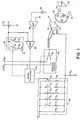
- FIG. l there is shown a schematic circuit diagram of the system for adjusting the image brightness in an electronic printer which displays images for photographic reproduction.
- the electronic image printer comprises a monochrome cathode ray tube l2 having a display screen l4 overlapped by a rotatably mounted filter wheel l6.
- the filter wheel l6, in turn, comprises the three primary red, green and blue color filters each one of which may be selectively moved into overlying relationship with respect to the display screen l4 by a motor drive l8.
- the light from the display screen l4 is transmitted through a selected one of the red, green and blue filters of the filter wheel l6 to a lens 20 from which it is imaged on the surface of a photosensitive material as shown at 22.
- the cathode ray tube l2, the filter wheel l6, the lens 20, and the photosensitive material 22 are all housed in a suitably lighttight chamber (not shown in the drawing).
- the motor l6, in turn, is controlled in a well-known manner in concert with the particular red, green or blue color separation video signal applied to the cathode ray tube l2 so that the appropriate one of the red, green and blue filters is moved into overlying relationship with respect to the display screen l4 to expose the photosensitive material 22 in a manner as is disclosed in U.S. Patent No. 4,438,453, entitled "Constant Light Greyscale Generator For CRT Color Camera System", by L. Alston, issued March 20, l984, and now incorporated by reference herein.
- the grid voltage applied to the cathode ray tube l2 is furnished from a positive voltage supply V2 and a negative voltage supply V1 by way of a resistor network shown generally at 24 and a resistor R9, respectively.
- the positive voltage supply V2 may be l2 volts
- the negative voltage supply V1 may be -l00 volts
- resistor R9 may be l00k ohms.
- the resistor network 24 comprises a plurality of resistors R1, R2, R3, R4 and R5 connected in serial relation, respectively, with a plurality of switch contacts S1, S2, S3, S4 and S5.
- the resistor network also preferably comprises another parallel connected resistor R8.
- the voltage applied to the grid terminal of the cathode ray tube l2 may be varied by closing selected ones of the switch contacts S1, S2. S3, S4 and S5 to achieve different parallel resistance combinations as will be subsequently described.
- mechanical switch contacts are shown for purposes of illustration, it will be readily understood that electronic switches, i.e., transistors, would comprise the preferred switch elements.
- Resistors R1. R2, R3, R4 and R5 may have typical values of 30k ohms, 62k ohms, l20k ohms, 240k ohms and 470k ohms, respectively, while resistor R8 may have a typical value of l2k ohms.
- the output signal from the photoresponsive element 26 is amplified by an amplifier 28 and thereafter directed to one input terminal of a comparator 30 for comparison with a select voltage reference signal applied to the other terminal of the comparator 30 and derived from a voltage supply V1 by way of a potentiometer P1 and a resistor network shown generally at 32.
- the resistor network 32 comprises resistors R6 and R7 connected, respectively, in serial relationship with switch contacts S6 and S7.
- the select voltage reference signal applied to the comparator 30 may be varied by selectively switching the switch contacts S6 and S7 to achieve different combinations of parallel resistance.
- the output from the comparator 30, in turn, is directed to a microprocessor 34 which operates to control the closure of the switch contacts S1 through S7 in the manner to be subsequently described.
- mechanical switch contacts are shown only for purposes of illustration and electronic switch components such as transistors would be preferred.
- An image defining electronic information signal is applied to a video terminal and thereafter directed to the cathode terminal of the cathode ray tube l2 by way of a monitor control as shown at 36.
- the monitor control 36 includes a switch contact S8 for switching the signal applied to the cathode of the cathode ray tube l2 between the image defining electronic information signal applied to the video terminal and a steady state select voltage reference level applied to the terminal V ref . Closure of the switch contact S8 is controlled by the microprocessor 34 in the manner to be herein described.
- the system of this example for adjusting the image brightness on the display screen l4 of the cathode ray tube l2 commences upon the microprocessor 34 providing the appropriate control signal to move switch contact S8 to the solid line position as shown thereby applying the steady state voltage V ref to the cathode terminal of the cathode ray tube l2.
- the display screen l4 thus displays a full screen raster of generally uniform light intensity across the face thereof at standard video field rates.
- the light emanating from the display screen l4 is detected by the photodiode 26 which is center weighted to detect primarily the light emanating from the center portion of the display screen l4 and provide an output signal corresponding to the light so detected.
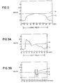
- the amplified output signal for one vertical field is shown graphically at A in FIG. 2.
- the other input terminal to the comparator 30 receives one of a select plurality of different voltage reference signals which are determined in accordance with the positions of the switch contacts S6 and S7 and the adjustment of the potentiometer P1.
- the switch contacts S6 and S7 are initially opened as shown in solid lines and the potentiometer P1 and voltage supply V1 selected to provide a l.5 volt reference voltage signal to the comparator 30 as shown graphically at B in FIG. 2.
- the microprocessor 34 interrogates the output signal from the comparator 30 at the middle of each vertical field to determine whether the appropriate grid voltage is being applied to the cathode ray tube l2. Referring to FIG. 2 it can be seen that the output signal A from the amplifier 28 at the center of the vertical field corresponds to the selected l.5 volt reference voltage so that no further adjustment to the grid voltage of the cathode ray tube l2 should be required to control the brightness of the display screen l4.
- the microprocessor 34 cannot determine whether the brightness of the display screen l4 is set to the appropriate brightness level as determined by the l.5 volt reference voltage or set to a brighter than desired level in comparison to the l.5 volt reference voltage.
- the microprocessor 34 therefore provides the appropriate control signal to switch one or more of the switch contacts S1 through S5 to effectively reduce the grid voltage applied to the cathode ray tube l2 and, in turn, decrease the intensity of the illumination emanating from the display screen l4.
- the light intensity from the display screen l4 detected by the photoresponsive element 26 thus decreases accordingly so as to provide a corresponding reduction in the amplitude of the output signal A.
- the comparator 30 responds to this reduction in the level of the output signal A to provide the appropriate signal to the microprocessor 34 that the value of the output signal A at the middle of the vertical field is less than the reference voltage B.
- the change in the output signal from the comparator 30 signals the microproceessor that the last incremental change in the resistance of the resistance network 24 resulted in the brightness of the display screen l4 decreasing across the selected level at which it is to be set to correspond to the select voltage reference B.
- the crossover point is determined for the adjustment of the grid voltage which controls the light intensity from the display screen l4 and no further switch contacts S1 through S5 are opened or closed.
- the microprocessor 34 provides a control signal to switch one or more of the switch contacts S1 through S5 to increase the grid voltage applied to the cathode ray tube l2 and thereby increase the light intensity emanating from the display screen l4.
- Photodiode 26 thereafter measures the increased light intensity emanating from the display screen l4 and provides a corresponding output signal to the amplifier 28 which, in turn, amplifies the output signal A to the comparator 30.
- the output from the comparator 30 switches so as to signal the microprocessr 34 that the light intensity of the display screen l4 has crossed over the voltage reference signal B and no further change in the position of the switch contacts S1 through S5 is required.
- the switch contacts S1 through S5 are arranged in a binary format and controlled by the microprocessor to close and/or open in select combinations for each incremental change in the light intensity of the display screen l4 which is thereafter detected by the photodetector 26 to determine whether the light intensity is crossed over with respect to the select voltage reference level B.
- the switch contacts of the network 24 that are opened and/or closed for each incremental resistance step are selected by the microprocessor 34 to effect the least significant change in resistance, which in our example is 470k ohms, thereby resulting in 32 different total steps of resistance to which the resistor network 24 may be switched by the microprocessor 34.
- each step in resistance for the resistor network 24 results in a corresponding change of l/l0th of a stop in the exposure of the photosensitive material 22 by virtue of the incremental change in the light intensity of the display screen l4.
- the resistive network may be switched through a plurality of succeeding resistive steps before the light intensity of the display screen l4 is increased or decreased sufficiently to effect a crossover in the output signal from the amplifier 28 relative to the select voltage reference signal B. Once the crossover is detected by the microprocessor 34, no further switching occurs within the resistor network 24 and the light intensity of the display screen l4 is adjusted to correspond to the select voltage reference signal B which for our example is initially l.5 volts.
- the microprocessor 34 signals the monitor control 36 to switch the switch contact S8 from its solid line position as shown to its phantom line position thereby applying an image defining electronic information signal from the video terminal to the cathode terminal of the cathode ray tube l2.
- the display screen l4 thereafter displays an image of the subject to be photographically reproduced on the photosensitive material 22, and the light intensity of the image is detected in the aforementioned manner by the photodetector 26.
- the output signal from the photodetector is amplified by the amplifier 28 to provide an output signal, as shown at C in FIG. 3A, to one input of the comparator 30.
- the comparator 30, compares the output signal A with the voltage reference signal B as shown in FIG. 3A.
- the microprocessor 34 reacts to the output signal from the comparator 30 at the center of the vertical field where it can be seen that the voltage reference signal B exceeds the level of the output signal A from the amplifier 28. This indicates that the cathode ray tube l2 grid voltage is set too high by virtue of its being adjusted in the aforementioned manner to correlate to a l.5 volt reference signal B.
- the microprocessor 34 thereafter provides a control signal to close one of the switch contacts S6, S7 to further reduce the voltage reference signal B level from l.5 volts to l volt as graphically shown at B′ in FIG. 3B.
- the light intensity of the image displayed on the display screen l4 is detected by the photodetector 26 and converted to the amplified electronic signal as shown at C in FIG. 3B for comparison with the newly established l volt reference signal B′.
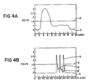
- FIGS. 4A and 4B there is shown at D the output signal from the amplifier 28 derived from the photodiode 26 detecting the light intensity of the display screen l4 upon the application of another image defining electronic information signal.
- dropping the l.5 volt reference signal B, by closing one of the switch contacts S6 or S7, to the l volt reference signal B′ is not sufficient to reduce the voltage reference signal B below the value at the center of the field of the output signal D from the amplifier 28.
- the remaining open switch contact of the switch contacts S6 and S7 must be closed to further reduce the voltage reference signal and thereby provide a 0.6 voltage reference signal B".
- the grid voltage to the cathode ray tube l2 provides for too dark an image and must be adjusted to brighten the image. This is accomplished by the microprocessor 34 switching the appropriate switch contacts S1 through S5 to decrease the resistance of the network 24 by two incremental steps of resistance thereby increasing the image brightness by 2/l0ths of a stop.
- the grid voltage to the cathode ray tube l2 is appropriately adjusted to correspond with one of four exposure ranges as determined by the amplitude of the output signal from the amplifier 28 as measured about the center of the field being: greater than l.5 volts or between l volt and l.5 volts or between 0.6 volts and l volt, or less than 0.6 volts.
- l.5, l and 0.6 volts defining the aforementioned four exposure ranges are described, it will be generally apparent that any number of different voltage reference signal levels defining corresponding numbers of exposure ranges may be utilized to achieve the appropriate brightness level of the image displayed on the display screen l4 for photographic reproduction on the photosensitive material 22.
- a color cathode ray tube could be used in place of the monochrome CRT l2 and filter wheel l6 thereby exposing the photosensitive material 22 to the full color image in a single exposure.
Landscapes
- Engineering & Computer Science (AREA)
- Multimedia (AREA)
- Signal Processing (AREA)
- Television Receiver Circuits (AREA)
- Controls And Circuits For Display Device (AREA)
- Projection-Type Copiers In General (AREA)
Applications Claiming Priority (2)
| Application Number | Priority Date | Filing Date | Title |
|---|---|---|---|
| US06/819,128 US4742397A (en) | 1986-01-16 | 1986-01-16 | System and method for adjusting image brightness in electronic printer |
| US819128 | 1986-01-16 |
Publications (3)
| Publication Number | Publication Date |
|---|---|
| EP0230361A2 true EP0230361A2 (de) | 1987-07-29 |
| EP0230361A3 EP0230361A3 (en) | 1988-10-12 |
| EP0230361B1 EP0230361B1 (de) | 1991-12-18 |
Family
ID=25227288
Family Applications (1)
| Application Number | Title | Priority Date | Filing Date |
|---|---|---|---|
| EP87300176A Expired EP0230361B1 (de) | 1986-01-16 | 1987-01-09 | Anordnung und Verfahren zur Helligkeitsregelung in einem elektronischen Drucker |
Country Status (5)
| Country | Link |
|---|---|
| US (1) | US4742397A (de) |
| EP (1) | EP0230361B1 (de) |
| JP (1) | JPS62189450A (de) |
| CA (1) | CA1278262C (de) |
| DE (1) | DE3775223D1 (de) |
Cited By (6)
| Publication number | Priority date | Publication date | Assignee | Title |
|---|---|---|---|---|
| EP0271178A3 (en) * | 1986-12-09 | 1989-05-24 | Canon Kabushiki Kaisha | Image processing apparatus |
| EP0393848A3 (de) * | 1989-04-21 | 1991-10-23 | Camtronics, Ltd. | Eichgerät für eine Lichtquelle zur Beleuchtung eines photographischen Films mit Bilddaten |
| EP0454086A3 (en) * | 1990-04-26 | 1992-04-22 | Honeywell Inc. | Compensation for drift in a cathode ray tube |
| EP0489758A4 (en) * | 1988-11-23 | 1992-12-02 | Hanoch Shalit | Photographic video recording processor and method |
| EP0542012A1 (de) * | 1991-11-13 | 1993-05-19 | Eastman Kodak Company | Kalibrierungsverfahren für Videobildwiedergabe mit elektronischem Drucker und Videomonitor |
| US5345315A (en) * | 1988-11-23 | 1994-09-06 | Imatec, Ltd. | Method and system for improved tone and color reproduction of electronic image on hard copy using a closed loop control |
Families Citing this family (5)
| Publication number | Priority date | Publication date | Assignee | Title |
|---|---|---|---|---|
| JPS63309077A (ja) * | 1987-06-11 | 1988-12-16 | Seikosha Co Ltd | ビデオプリンタ |
| DE3721326A1 (de) * | 1987-06-27 | 1989-01-12 | Triumph Adler Ag | Ansteuerverfahren fuer eine bildroehre mit unterschiedlich dicker frontscheibe und schaltungsanordnung zur durchfuehrung des verfahrens |
| US4999791A (en) * | 1988-12-23 | 1991-03-12 | Schumann Robert W | Computer graphics color film recording method and apparatus |
| US5303056A (en) * | 1992-09-14 | 1994-04-12 | Eastman Kodak Company | Dynamic gain correction for CRT printing |
| US5843615A (en) * | 1995-12-04 | 1998-12-01 | Avery Dennison Corporation | Image-recording technology |
Family Cites Families (16)
| Publication number | Priority date | Publication date | Assignee | Title |
|---|---|---|---|---|
| US3441663A (en) * | 1965-05-04 | 1969-04-29 | Photo Electronics Corp | Non-linear amplifiers and systems |
| US3469142A (en) * | 1967-06-20 | 1969-09-23 | Spedcor Electronics Inc | Intensity control circuit for oscilloscope or the like |
| US3564137A (en) * | 1968-01-26 | 1971-02-16 | Motorola Inc | Automatic brightness compensation circuit |
| US3597540A (en) * | 1969-04-01 | 1971-08-03 | Motorola Inc | Automatic brightness control responsive to black level of video signal |
| US3700329A (en) * | 1971-08-02 | 1972-10-24 | Logetronics Inc | Radiographic reduction system |
| US3917974A (en) * | 1973-11-23 | 1975-11-04 | Searle & Co | Scintillation camera brightness calibrating apparatus |
| US4027315A (en) * | 1975-10-03 | 1977-05-31 | Dunn Instruments, Inc. | Multiple image camera |
| US4240729A (en) * | 1977-02-14 | 1980-12-23 | Dunn Instruments, Inc. | Multiple image camera |
| US4126884A (en) * | 1977-05-05 | 1978-11-21 | Rca Corporation | Kinescope beam current limiter employing automatic sequential control of image contrast and brightness to limit beam current |
| US4433345A (en) * | 1981-06-19 | 1984-02-21 | Loge/Dunn Instruments, Inc. | Video image recording methods and devices |
| US4530011A (en) * | 1981-06-19 | 1985-07-16 | Loge/Dunn Instruments, Inc. | Apparatus for maintaining of a cathode ray tube image within the light acceptance range of a photographic film |
| US4415921A (en) * | 1981-10-30 | 1983-11-15 | Nicolet Instrument Corporation | Automatic calibration system for video displays in vision testing |
| US4473849A (en) * | 1981-12-21 | 1984-09-25 | Image Resource Corporation | System and apparatus for conversion of video signals to film images |
| US4438453A (en) * | 1982-01-21 | 1984-03-20 | Polaroid Corporation | Constant light greyscale generator for CRT color camera system |
| US4679087A (en) * | 1984-03-12 | 1987-07-07 | Loge/Dunn Instruments, Inc. | Method and apparatus for photographing video images of either polarity without CRT brightness or contrast readjustment |
| US4631576A (en) * | 1984-11-13 | 1986-12-23 | Hazeltine Corporation | Nonuniformity correction system for color CRT display |
-
1986
- 1986-01-16 US US06/819,128 patent/US4742397A/en not_active Expired - Lifetime
-
1987
- 1987-01-07 CA CA000526811A patent/CA1278262C/en not_active Expired - Fee Related
- 1987-01-09 EP EP87300176A patent/EP0230361B1/de not_active Expired
- 1987-01-09 DE DE8787300176T patent/DE3775223D1/de not_active Expired - Fee Related
- 1987-01-14 JP JP62007387A patent/JPS62189450A/ja active Pending
Cited By (7)
| Publication number | Priority date | Publication date | Assignee | Title |
|---|---|---|---|---|
| EP0271178A3 (en) * | 1986-12-09 | 1989-05-24 | Canon Kabushiki Kaisha | Image processing apparatus |
| US4864419A (en) * | 1986-12-09 | 1989-09-05 | Canon Kabushiki Kaisha | Image processing apparatus |
| EP0489758A4 (en) * | 1988-11-23 | 1992-12-02 | Hanoch Shalit | Photographic video recording processor and method |
| US5345315A (en) * | 1988-11-23 | 1994-09-06 | Imatec, Ltd. | Method and system for improved tone and color reproduction of electronic image on hard copy using a closed loop control |
| EP0393848A3 (de) * | 1989-04-21 | 1991-10-23 | Camtronics, Ltd. | Eichgerät für eine Lichtquelle zur Beleuchtung eines photographischen Films mit Bilddaten |
| EP0454086A3 (en) * | 1990-04-26 | 1992-04-22 | Honeywell Inc. | Compensation for drift in a cathode ray tube |
| EP0542012A1 (de) * | 1991-11-13 | 1993-05-19 | Eastman Kodak Company | Kalibrierungsverfahren für Videobildwiedergabe mit elektronischem Drucker und Videomonitor |
Also Published As
| Publication number | Publication date |
|---|---|
| US4742397A (en) | 1988-05-03 |
| CA1278262C (en) | 1990-12-27 |
| JPS62189450A (ja) | 1987-08-19 |
| EP0230361A3 (en) | 1988-10-12 |
| EP0230361B1 (de) | 1991-12-18 |
| DE3775223D1 (de) | 1992-01-30 |
Similar Documents
| Publication | Publication Date | Title |
|---|---|---|
| CA1210134A (en) | Endoscope signal level control | |
| EP0230361B1 (de) | Anordnung und Verfahren zur Helligkeitsregelung in einem elektronischen Drucker | |
| CA1309166C (en) | Image sensing apparatus having automatic iris function of automatically adjusting exposure in response to video signal | |
| EP0097032B1 (de) | Elektronische Kameras | |
| US5298993A (en) | Display calibration | |
| JP3412174B2 (ja) | 自動露光制御装置 | |
| US4638350A (en) | Color image sensing device | |
| US5815204A (en) | Strobe apparatus of a still video camera with adjustable color temperature | |
| USRE39410E1 (en) | White balance adjusting device for a camera | |
| JPH03204281A (ja) | 撮像装置 | |
| US5283655A (en) | Video camera apparatus having solid state imager | |
| US4750032A (en) | Automatic white balance adjusting system for a color video camera | |
| JPH031772A (ja) | 撮像装置 | |
| US5764287A (en) | Image pickup apparatus with automatic selection of gamma correction valve | |
| JP2528368B2 (ja) | カメラ | |
| JP2698296B2 (ja) | 画像処理回路 | |
| US4472743A (en) | Automatic diaphragm control device for a closed circuit television camera | |
| US5255077A (en) | White balance control based upon magnitude of flicker | |
| US5231515A (en) | Image reading device | |
| JPH03106269A (ja) | ビデオカメラの映像信号処理装置 | |
| JPH08107560A (ja) | 画像入力装置 | |
| JP2839202B2 (ja) | 撮像装置の自動露光制御装置及び方法 | |
| EP0436442A2 (de) | Schaltung zur automatischen Regelung des Weiss- und Schwarzabgleiches und deren Verfahren | |
| JPH01240082A (ja) | 露光制御装置 | |
| EP0420621A2 (de) | Verfahren und Einrichtung zur Weissabgleichssteuerung für eine Bildaufnahmevorrichtung |
Legal Events
| Date | Code | Title | Description |
|---|---|---|---|
| PUAI | Public reference made under article 153(3) epc to a published international application that has entered the european phase |
Free format text: ORIGINAL CODE: 0009012 |
|
| AK | Designated contracting states |
Kind code of ref document: A2 Designated state(s): DE FR GB NL |
|
| PUAL | Search report despatched |
Free format text: ORIGINAL CODE: 0009013 |
|
| AK | Designated contracting states |
Kind code of ref document: A3 Designated state(s): DE FR GB NL |
|
| 17P | Request for examination filed |
Effective date: 19890406 |
|
| 17Q | First examination report despatched |
Effective date: 19910301 |
|
| GRAA | (expected) grant |
Free format text: ORIGINAL CODE: 0009210 |
|
| AK | Designated contracting states |
Kind code of ref document: B1 Designated state(s): DE FR GB NL |
|
| ET | Fr: translation filed | ||
| PGFP | Annual fee paid to national office [announced via postgrant information from national office to epo] |
Ref country code: FR Payment date: 19920110 Year of fee payment: 6 |
|
| PGFP | Annual fee paid to national office [announced via postgrant information from national office to epo] |
Ref country code: GB Payment date: 19920115 Year of fee payment: 6 |
|
| PGFP | Annual fee paid to national office [announced via postgrant information from national office to epo] |
Ref country code: DE Payment date: 19920120 Year of fee payment: 6 |
|
| REF | Corresponds to: |
Ref document number: 3775223 Country of ref document: DE Date of ref document: 19920130 |
|
| PGFP | Annual fee paid to national office [announced via postgrant information from national office to epo] |
Ref country code: NL Payment date: 19920131 Year of fee payment: 6 |
|
| PLBE | No opposition filed within time limit |
Free format text: ORIGINAL CODE: 0009261 |
|
| STAA | Information on the status of an ep patent application or granted ep patent |
Free format text: STATUS: NO OPPOSITION FILED WITHIN TIME LIMIT |
|
| 26N | No opposition filed | ||
| PG25 | Lapsed in a contracting state [announced via postgrant information from national office to epo] |
Ref country code: GB Effective date: 19930109 |
|
| PG25 | Lapsed in a contracting state [announced via postgrant information from national office to epo] |
Ref country code: NL Effective date: 19930801 |
|
| GBPC | Gb: european patent ceased through non-payment of renewal fee |
Effective date: 19930109 |
|
| NLV4 | Nl: lapsed or anulled due to non-payment of the annual fee | ||
| PG25 | Lapsed in a contracting state [announced via postgrant information from national office to epo] |
Ref country code: FR Effective date: 19930930 |
|
| PG25 | Lapsed in a contracting state [announced via postgrant information from national office to epo] |
Ref country code: DE Effective date: 19931001 |
|
| REG | Reference to a national code |
Ref country code: FR Ref legal event code: ST |