EP0230396A2 - Magnetic pilot expansion valve system and method - Google Patents
Magnetic pilot expansion valve system and method Download PDFInfo
- Publication number
- EP0230396A2 EP0230396A2 EP87630008A EP87630008A EP0230396A2 EP 0230396 A2 EP0230396 A2 EP 0230396A2 EP 87630008 A EP87630008 A EP 87630008A EP 87630008 A EP87630008 A EP 87630008A EP 0230396 A2 EP0230396 A2 EP 0230396A2
- Authority
- EP
- European Patent Office
- Prior art keywords
- plunger
- pilot
- expansion valve
- magnetic
- pressure differential
- Prior art date
- Legal status (The legal status is an assumption and is not a legal conclusion. Google has not performed a legal analysis and makes no representation as to the accuracy of the status listed.)
- Withdrawn
Links
- 238000000034 method Methods 0.000 title claims abstract description 9
- 239000012530 fluid Substances 0.000 claims abstract description 47
- 230000001105 regulatory effect Effects 0.000 claims abstract description 19
- 238000004891 communication Methods 0.000 claims abstract description 13
- 230000001276 controlling effect Effects 0.000 claims abstract description 8
- 230000008859 change Effects 0.000 claims description 9
- 238000012886 linear function Methods 0.000 claims description 2
- 239000003507 refrigerant Substances 0.000 description 17
- 239000003570 air Substances 0.000 description 11
- 239000007788 liquid Substances 0.000 description 11
- 238000005057 refrigeration Methods 0.000 description 11
- 230000008878 coupling Effects 0.000 description 7
- 238000010168 coupling process Methods 0.000 description 7
- 238000005859 coupling reaction Methods 0.000 description 7
- 230000004044 response Effects 0.000 description 7
- 230000009471 action Effects 0.000 description 3
- 238000010276 construction Methods 0.000 description 3
- 230000000694 effects Effects 0.000 description 3
- 230000006835 compression Effects 0.000 description 2
- 238000007906 compression Methods 0.000 description 2
- 238000007667 floating Methods 0.000 description 2
- 239000000314 lubricant Substances 0.000 description 2
- 238000005259 measurement Methods 0.000 description 2
- 238000011144 upstream manufacturing Methods 0.000 description 2
- 235000014676 Phragmites communis Nutrition 0.000 description 1
- 238000004378 air conditioning Methods 0.000 description 1
- 239000012080 ambient air Substances 0.000 description 1
- 238000000418 atomic force spectrum Methods 0.000 description 1
- 230000008901 benefit Effects 0.000 description 1
- 238000013461 design Methods 0.000 description 1
- 238000010438 heat treatment Methods 0.000 description 1
- 239000010687 lubricating oil Substances 0.000 description 1
- 238000011084 recovery Methods 0.000 description 1
- 238000012360 testing method Methods 0.000 description 1
- 238000012546 transfer Methods 0.000 description 1
Images


Classifications
-
- G—PHYSICS
- G05—CONTROLLING; REGULATING
- G05D—SYSTEMS FOR CONTROLLING OR REGULATING NON-ELECTRIC VARIABLES
- G05D16/00—Control of fluid pressure
- G05D16/20—Control of fluid pressure characterised by the use of electric means
- G05D16/2093—Control of fluid pressure characterised by the use of electric means with combination of electric and non-electric auxiliary power
Definitions
- This invention relates to a system and method for controlling the flow rate of fluid through an expansion valve in a refrigeration system or the like and, more particularly, to a magnetic pilot for controlling such an expansion valve.
- a refrigeration system includes a compressor, a condenser coil, and an evaporator coil.
- Refrigerant vapor is compressed to a high pressure by the compressor and is conducted through the condenser coil where it is cooled to form a liquid under high pressure.
- This high pressure liquid is then adiabatically expanded through an expansion valve and is admitted into the evaporator coil where the refrigerant picks up heat from the surroundings of the coil.
- the heat transforms low pressure liquid in the evaporator coil into a vapor.
- the vapor is then conducted through the suction line of the refrigeration system and is returned to the inlet of the compressor.
- a thermostatic expansion valve has conventionally been used to regulate the flow of refrigerant through the evaporator coil so that under various operating conditions for the evaporator coil, the majority of the length of the coil will have liquid refrigerant therein, while flow is limited so as to ensure that the evaporator coil does not become flooded.
- the thermostatic expansion valve automatically controls the flow of refrigerant into the evaporator coil so as to maintain the superheat of the refrigerant leaving the evaporator coil at a predetermined level under various operating conditions.
- the superheat setting may only be changed by mechanically adjusting or varyingl'the spring force exerted on the valve, or by changing the fluid in the thermostatic sensing bulb so as to exert more or less pressure on the expansion valve diaphragm at selected temperatures.
- these adjustments are not always practical or desirable.
- electrically operated refrigerant expansion valves such as shown in the co-assigned U.S. Patent 3,967, 781 to Kunz, have been employed in conjunction with a control system responsive to a parameter, such as the temperature of the lubricant in the sump of the compressor, or to ambient air temperature, to modulate the superheat setting of the electrically operable expansion valve.
- a control system for such an electrically operable refrigerant expansion valve is disclosed in the co-assigned U.S. Patent 4,067,203 to Behr.
- the control system disclosed in the Behr patent enabled the precise control of the electrically operated expansion valve so that the evaporator coil could be continuously operated with liquid refrigerant in all parts of the coil under varying load conditions, and yet prevented liquid refrigerant from entering the suction side of the compressor. It will be recognized that when the evaporator coil is maintained in its flooded or wetted state, optimum heat transfer, and thus optimum operating efficiency, for the refrigeration system results.
- This apparatus includes an electric heater for biasing the thermostatic sensing bulb of the thermostatic expansion valve and a control for the heater which is responsive to a refrigeration system parameter, such as the temperature of the lubricant in the compressor sump, so as to effect an increase in the temperature of the thermostatic bulb above the refrigerant temperature upon an indicated change in the parameter being monitored to, in effect, reduce the superheat setting of the thermostatic expansion valve and to increase the flow of refrigerant through the refrigeration system.
- the heater is de-energized, or at least the heater power is reduced, to effect an increase in the superheat setting of the thermostatic expansion valve and to reduce the flow of refrigerant.
- a magnetic pilot for an expansion valve of the present invention includes a pilot body having first, second and third ports in fluid communication with one another.
- the first and second ports are adapted for flow of fluid therebetween, and the second and third ports are adapted to supply a pressure differential to a control element of an expansion valve.
- An assembly including a valve seat and a plunger are disposed in the fluid path between the first and second ports of the magnetic pilot for regulating a pressure differential supplied to the control element, which pressure differential is substantially independent of changes in fluid pressure at the first and second ports.
- the regulating assembly includes means for applying a magnetic force to the plunger to oppose the flow of fluid between the first and second ports.
- the regulating assembly also includes means for electrically setting the magnitude of the magnetic force applied to the plunger.
- the pressure differential is a function of that magnetic force.
- an expansion valve system in a second aspect of the present invention, includes an expansion valve having an inlet port, an outlet port, a passage between the inlet and outlet ports for fluid communication therebetween, and a valve assembly at least partially disposed in the passage between the inlet and outlet ports for controlling the amount of fluid flow between the ports.
- the valve assemby includes a pressure responsive control element.
- the expansion valve system also includes a magnetic pilot having means for supplying a regulated pressure differential to the pressure responsive control element of the expansion valve. The pressure differential is substantially independent of changes in fluid pressure at the inlet and outlet ports of the expansion valve.
- a method of controlling the flow rate of fluid through an expansion valve or the like includes the steps of developing a regulated pressure differential in an electrically controlled magnetic pilot, applying the regulated pressure differential across a control element of the expansion valve, and opening the expansion valve an amount corresponding to the pressure differential across the control element, whereby flow through the expansion valve is a function of the regulated pressure differential.
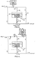
- an electrically controlled expansion valve system 11 of the present invention includes an expansion valve 13 having an inlet port 15 and an exit port 17.
- the expansion valve shown has a conventional diaphragm control element mounted in a diaphragm housing 19, although the expansion valve could just as easily be a conventional piston-controlled valve.
- the magnetic pilot 21 in the present invention is mounted above the expansion valve, and includes two main portions. The first is the electrically controlled solenoid 23. The second is the valve body 25 for the pilot itself. The valve body of the pilot is connected by : .means of two tubes 27 and 29 to the inlet and outlet ports of the expansion valve.
- magnetic pilot 21 supplies a regulated pressure differential to the pressure responsive control element, in this case, the diaphragm, of the expansion valve. Because of the particular construction and placement of the magnetic pilot, this pressure differential is substantially independent of changes in fluid pressure at the inlet and outlet ports 15 and 17 of the expansion valve.
- This particular pilot can drive refrigeration systems of from 10 to 200 tons with suitable expansion valves, although systems outside this range could also fall within the scope of the present invention.
- Solenoid 23 is controlled by means of a suitable controller, such as controller 31 (Fig. 2).
- Controller 31 includes two terminals 33 for supplying current to solenoid 23. That current is obtained from a suitable power source by a power supply cord 35, and is suitably transformed and regulated by controller 31.
- a pair of terminals 37 is provided for those instances in which it is desired to control the magnetic pilot using an external controller such as a microcomputer. In this latter case, controller 31 simply supplies and regulates the current in an amount determined by the voltage across remote input terminals 37.
- a two-position switch 39 is provided to chose between local or remote control of the current provided to the solenoid of the magnetic pilot. Normally, one would control the magnetic pilot using the remote inputs. However, for experimental purposes or the like, it might be desired to control the pilot manually. Manual control knob 41 and two test terminals 43 are provided for this purpose.
- an expansion valve 45 has a control element 47 (which can be a piston or a diaphragm) which is biased upwardly by a compression spring 49.
- a valve element 51 of the expansion valve is in its closed position.
- the position of valve element 51 is controlled by the pressure differential across control element 47.
- This pressure differential is supplied to the control element by means of two passages 53 and 55.
- the electrically controlled pilot 57 of the prior art device is disposed in a passage 59 connected to the inlet of the expansion valve.
- a fixed restrictor 61 is disposed downstream from passage 53 in passage 59, so that the pressure differential across the control element 47 is a function both of the fixed restrictor and of the position of the valve member in pilot valve 57.
- Passage 55 is connected directly to the outlet of the main expansion valve, so that the pressure differential across control element 47 is related to the position taken by the valve member of electrically controlled pilot 57 and the outlet pressure of the expansion valve.
- the pressure differential across the control element 47 is not the same as the pressure differential across the electrically controlled pilot 57.
- the present invention utilizes a magnetic pilot which is disposed directly across the control element of the expansion valve 45.
- Magnetic pilot 21 has its inlet port 62 connected directly to passage 53 and its exit port 63 connected directly to passage 55. That is, the valve element 65 of magnetic pilot 21 directly controls the pressure differential across the control element 47 of the expansion valve.
- valve element 65 is connected to the plunger 67 of solenoid 23. Valve element 65, when closed, sits on an annular valve seat 69 which encircles the valve element inlet port 62. As a result of this configuration, a small change in the position of valve element 65 results in a :large change in the pressure drop across the valve element.
- Fixed restrictor 61 in the present invention is disposed upstream of the magnetic pilot, and in one embodiment of the present invention, a liquid stop check valve 71 is provided to mechanically close off flow of fluid through the magnetic pilot when the solenoid is de-energized.
- valve element 51 of the expansion valve in the present invention is little affected by changes in valve inlet pressure or outlet pressure, which results in accurate, stable control of the system.
- valve element 65 and valve seat 69 in the magnetic pilot because of the design of the valve element 65 and valve seat 69 in the magnetic pilot, the plunger movement, when the pressure is being modulated, is extremely small. A small movement of the plunger results in a relatively large change in the flow through the pilot. This minimizes the variable of plunger force versus stroke typical of solenoid-type valves.
- the pressure set point is directly and linearly proportional to the power supplied to the coil.
- magnetic pilot 21 is actually a pressure regulator which maintains its set point pressure differential (which is set by the solenoid coil current) and compensates for any change in system conditions.
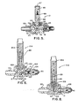
- Magnetic pilot 21 (Fig. 5) includes a valve body 73 having a number of passages 53,75,77,79, and 81 therein.
- Passage 75 extends from fixed restrictor 61 to passage 77.
- Passage 53 is in fluid communication and opens into passage 77 and connects that passageway with the upper side of control element 47 of the expansion valve.
- Passage 77 terminates at its upper end in inlet port 62 of the pilot valve itself.
- Inlet port 62 is surrounded by generally annular valve seat 69.
- valve element 65 Disposed above valve seat 69 is valve element 65, which is integral with plunger 83 of solenoid 23.
- Plunger 83 is secured at its upper end to a magnetically movable member 85 which is enclosed in a housing 87.
- Housing 87 is secured at its lower end to valve body 73.
- An air gap 89 of approximately 0.03 inch exists between magnetically movable member 85 and a stationary member 91 disposed annularly around plunger 83, which stationary member does not move with respect to housing 87, although it is contained therein.
- the plunger air gap 89 is mechanically prevented from completely closing because the valve element seats on valve seat 69 before the air gap is closed.
- This arrangement allows the modulation of the pressure to occur at a small air gap, which is a very high force range, while preventing the plunger from latching closed.
- the variable of plunger force as a function of the air gap is minimized.
- Pilot 21 does not include means for biasing the plunger in one direction or the other.
- the only significant forces affecting the position of the valve element with respect to the valve seat are the force exerted by the flow of current through the solenoid coil and the magnetic force resulting from the pressure differential across valve.element 65 itself.
- Outlet or exit port 63 is disposed in valve body 53 adjacent valve seat 69. Exit port 63 is connected by passage 79 to passage 81. Passage 81 is in fluid communication with a coupling 93 by means of which tube 29 (Fig. 1) connects the magnetic pilot to the outlet side of the expansion valve. A similar coupling 95 is provided to permit the attachment of tube 27 to the:magnetic pilot. Coupling 95, like coupling 93, has an interior bore. In the case of coupling 95, the interior bore is in fluid communication with fixed restrictor 61.
- Magnetic pilot 21 uses the magnetic force generated by the solenoid coil and plunger 83 to modulate a controlled pilot pressure across valve element 65.
- the pilot pressure on the high side of valve member 65 is directed by means of passage 53 to the signal side of the control element 47 (the piston or diaphragm) of the expansion valve.
- the exhaust or outlet side of pilot 21 is connected by means of passages 79, 81, coupling 93, tube 29 and passage 55 to the outlet side of the control element 47 so that the pilot controls the pressure differential across the expansion valve control element.
- This pressure differential is used to drive the expansion valve through its opening pressure gradient, which results in an electrically applied signal being translated into a percentage of valve opening.
- pilot valve element 65 The combination of the magnetic force driving the plunger downwardly and the force generated by the exhaust or outlet pressure of the pilot act downwardly through pilot valve element 65. These forces are offset by the fluid pressure acting upwardly through the valve inlet port 62. The plunger and valve element move in response to this force of balance, which results in a controlled pressure that is proportional to the plunger force.
- FIG. 6 An alternative embodiment of magnetic pilot 21 is shown in Fig. 6 and labeled 21A.
- This pilot differs from the one shown in Fig. 5 in that it includes check valve 71 to mechanically close the fluid flow path when the solenoid is de-energized. It also differs in that the air gap is not horizontal, but rather is angled. This latter feature, in some applications, could result in even more linear operation of the pilot than is achieved with the embodiment of Fig. 5, although it has been discovered that the embodiment of Fig. 5, even though less complex, has a very linear response.
- the valve body of pilot 21A (labeled 73A) has its controlled pressure port 53 extending downwardly from a passage 97 which terminates at its upper extent in valve seat 99.
- Solenoid plunger 83 in this embodiment, is again integral with valve element 65, but a pin 101 extends integrally down from valve element 65 in passage 97.
- pin 101 When the solenoid is energized to drive plunger 83 downwardly, pin 101 is driven downwardly in passage 97 where it strikes a check valve connecting rod 103.
- This movement forces check valve 71 open, thereby permitting fluid flow from the inlet side of the expansion valve into passage 97.
- tube 27 (Fig. 1) is connected by a coupling 105, which contains fixed restrictor 61 in the upstream part of an internal bore, to check valve 71.
- check valve 71 When check valve 71 is open as described above, a fluid path exists between fixed restrictor 61 and passageway 97.
- check valve 71 can be biased in any conventional manner, such as by a compression spring 108.
- the solenoid coil When the solenoid coil is de-energized, the plunger tends to be forced by the fluid pressure to its uppermost position, allowing the spring-loaded check valve to move to its normally closed position. This shuts off all flow through the pilot.
- the plunger When the coil is energized, the plunger forces the ramped surface on the end of the plunger pin past the check valve connecting rod 103. This action mechanically strokes check valve 71 open.
- the high pressure actuating fluid e-iters the pilot through fixed diameter orifice 61, past check valve 71, and into the port area encircled by plunger seat 99 by way of passage 97.
- the modulation of the pressure differential then proceeds as described above.
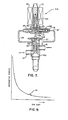
- the magnetic pilot of Fig. 6 is shown in Fig. 7 in combination with an expansion valve 13A having a diaphragm for a control element. It is more clearly seen in this Figure that high pressure fluid from inlet port 15 is supplied by tube 27 to fixed restrictor 61.
- check valve 71 When check valve 71 is forced open as described above by pin 101 and check valve connecting rod 103, the pilot pressure which is regulated by magnetic pilot 21 is supplied by way of passage 53 to the control .side of diaphragm 47.
- the exhaust side of the magnetic pilot is connected by tube 29 to the other side of diaphragm 47, so that the pressure differential across diaphragm 47 is exactly the same as that across valve element 65 in the magnetic pilot.
- Tube 29 is also connected through a passage 107 to outlet port 17 of the expansion valve.
- Expansion valve 13 is otherwise conventional and not described in detail herein. Of course for applications requiring a heavy duty expansion valve, diaphragm 47 could be replaced by a piston control element, as is well known in the art.
- solenoid 23 When solenoid 23 is de-energized, the forces on plunger 83 cause the plunger to be forced upwardly, which results in check valve 71 being biased to its closed position shown in Fig. 7.
- FIG. 8 Another embodiment of the magnetic pilot of the present invention, labelled 21B, is shown in Fig. 8.
- This embodiment is very similar to that of Fig. 6, but instead of having fixed pin 101 attached to the plunger, it has a floating plunger pin 109, which floats in passage 97.
- the plunger when the solenoid is energized, provides a hammer blow action to drive the pin down and open check valve 71.
- the floating action allows plunger 83 to move freely without the drag otherwise resulting from the check valve connecting rod 103.
- the magnetic force applied by a solenoid is a function of the air gap between movable and stationary parts of the plunger.
- the magnitude of this force as a function of the air gap is illustrated in Fig. 9.
- Fig. 9 With the present configuration, it is possible to operate in a fairly linear portion of the air gap versus force curve, which portion is labeled 111 in Fig.9.Since the stroke is limited to about 0.00254 cm (.002 inch) the change in magnetic force throughout the stroke is extremely linear and fairly constant.
- the percentage flow through expansion valve 13 is also a fairly smooth function of the current applied to solenoid 23. The curve representing this flow as a function of solenoid current is shown in Fig. 10.
- a circuit such as shown in Fig. 11 can be used to change the current supplied to the solenoid 23 to compensate for the non-linearity in Fig.10.
- This particular circuit has two break points at which the slope of the output is changed. One break point is controlled by an operational amplifier U1 in combination with a zener diode Z1, while the second is controlled by a second operational amplifier U3, having three diodes D1, D2, and D3 in a feedback loop.
- the output of amplifier U3 as a function of its input changes slope so that the current actually supplied to the solenoid coils is changed sufficiently to give a linear response of percentage flow through the expansion valve with respect to the input signal.
- the output of amplifier U3 is supplied through a third operational amplifier U5 to a MOSFET Q1 which controls the amount of current which flows through coil 23.
Landscapes
- Physics & Mathematics (AREA)
- Fluid Mechanics (AREA)
- General Physics & Mathematics (AREA)
- Engineering & Computer Science (AREA)
- Automation & Control Theory (AREA)
- Magnetically Actuated Valves (AREA)
Applications Claiming Priority (2)
| Application Number | Priority Date | Filing Date | Title |
|---|---|---|---|
| US82216086A | 1986-01-24 | 1986-01-24 | |
| US822160 | 1986-01-24 |
Publications (1)
| Publication Number | Publication Date |
|---|---|
| EP0230396A2 true EP0230396A2 (en) | 1987-07-29 |
Family
ID=25235329
Family Applications (1)
| Application Number | Title | Priority Date | Filing Date |
|---|---|---|---|
| EP87630008A Withdrawn EP0230396A2 (en) | 1986-01-24 | 1987-01-20 | Magnetic pilot expansion valve system and method |
Country Status (3)
| Country | Link |
|---|---|
| EP (1) | EP0230396A2 (da) |
| JP (1) | JPS62171578A (da) |
| DK (1) | DK36887A (da) |
Cited By (1)
| Publication number | Priority date | Publication date | Assignee | Title |
|---|---|---|---|---|
| US6658877B2 (en) * | 2001-05-26 | 2003-12-09 | Danfoss A/S | Valve arrangement with expansion valve |
-
1987
- 1987-01-20 EP EP87630008A patent/EP0230396A2/en not_active Withdrawn
- 1987-01-21 JP JP62012166A patent/JPS62171578A/ja active Pending
- 1987-01-23 DK DK036887A patent/DK36887A/da not_active Application Discontinuation
Cited By (1)
| Publication number | Priority date | Publication date | Assignee | Title |
|---|---|---|---|---|
| US6658877B2 (en) * | 2001-05-26 | 2003-12-09 | Danfoss A/S | Valve arrangement with expansion valve |
Also Published As
| Publication number | Publication date |
|---|---|
| JPS62171578A (ja) | 1987-07-28 |
| DK36887D0 (da) | 1987-01-23 |
| DK36887A (da) | 1987-07-25 |
Similar Documents
| Publication | Publication Date | Title |
|---|---|---|
| US5629660A (en) | Expansion valve for air conditioning system with proportional solenoid | |
| US4685309A (en) | Pulse controlled expansion valve for multiple evaporators and method of controlling same | |
| USRE33775E (en) | Pulse controlled expansion valve for multiple evaporators and method of controlling same | |
| EP1052463B1 (en) | Expansion valve | |
| US4448038A (en) | Refrigeration control system for modulating electrically-operated expansion valves | |
| US3577743A (en) | Control for refrigeration systems | |
| US4362027A (en) | Refrigeration control system for modulating electrically-operated expansion valves | |
| CA2063904C (en) | Modulated temperature control for environmental chamber | |
| US4459819A (en) | Pulse controlled expansion valve and method | |
| US4067203A (en) | Control system for maximizing the efficiency of an evaporator coil | |
| US3545472A (en) | Transducer | |
| US4080110A (en) | Control system for variable capacity gas compressor | |
| US5289692A (en) | Apparatus and method for mass flow control of a working fluid | |
| US3914952A (en) | Valve control means and refrigeration systems therefor | |
| US5460349A (en) | Expansion valve control element for air conditioning system | |
| US3324674A (en) | Refrigeration control apparatus | |
| US4425767A (en) | Refrigeration control system for modulating electrically-operated expansion valves | |
| US2583178A (en) | Refrigeration control apparatus | |
| EP0021745A1 (en) | An automatic temperature control system for a vehicle passenger compartment | |
| US4892285A (en) | Modulated electrically operated refrigerant expansion valve | |
| US3405535A (en) | Temperature controlled flow control device and refrigeration system including such device | |
| EP0230396A2 (en) | Magnetic pilot expansion valve system and method | |
| US3791160A (en) | Air conditioning system with temperature responsive controls | |
| EP1265041B1 (en) | Refrigerating cycle | |
| US4318509A (en) | Fluid temperature control system |
Legal Events
| Date | Code | Title | Description |
|---|---|---|---|
| PUAI | Public reference made under article 153(3) epc to a published international application that has entered the european phase |
Free format text: ORIGINAL CODE: 0009012 |
|
| AK | Designated contracting states |
Kind code of ref document: A2 Designated state(s): AT BE CH DE ES FR GB IT LI NL SE |
|
| STAA | Information on the status of an ep patent application or granted ep patent |
Free format text: STATUS: THE APPLICATION HAS BEEN WITHDRAWN |
|
| 18W | Application withdrawn |
Withdrawal date: 19880309 |
|
| RIN1 | Information on inventor provided before grant (corrected) |
Inventor name: PALMER, STEPHEN GEORGE Inventor name: YERLIKAYA, DENIS YALCIN |