EP0230447B1 - Ausgabeüberwachungssystem - Google Patents
Ausgabeüberwachungssystem Download PDFInfo
- Publication number
- EP0230447B1 EP0230447B1 EP86904539A EP86904539A EP0230447B1 EP 0230447 B1 EP0230447 B1 EP 0230447B1 EP 86904539 A EP86904539 A EP 86904539A EP 86904539 A EP86904539 A EP 86904539A EP 0230447 B1 EP0230447 B1 EP 0230447B1
- Authority
- EP
- European Patent Office
- Prior art keywords
- processor
- item
- price
- light source
- microprocessor
- Prior art date
- Legal status (The legal status is an assumption and is not a legal conclusion. Google has not performed a legal analysis and makes no representation as to the accuracy of the status listed.)
- Expired
Links
Images




Classifications
-
- G—PHYSICS
- G06—COMPUTING OR CALCULATING; COUNTING
- G06K—GRAPHICAL DATA READING; PRESENTATION OF DATA; RECORD CARRIERS; HANDLING RECORD CARRIERS
- G06K7/00—Methods or arrangements for sensing record carriers, e.g. for reading patterns
- G06K7/10—Methods or arrangements for sensing record carriers, e.g. for reading patterns by electromagnetic radiation, e.g. optical sensing; by corpuscular radiation
- G06K7/10544—Methods or arrangements for sensing record carriers, e.g. for reading patterns by electromagnetic radiation, e.g. optical sensing; by corpuscular radiation by scanning of the records by radiation in the optical part of the electromagnetic spectrum
- G06K7/10821—Methods or arrangements for sensing record carriers, e.g. for reading patterns by electromagnetic radiation, e.g. optical sensing; by corpuscular radiation by scanning of the records by radiation in the optical part of the electromagnetic spectrum further details of bar or optical code scanning devices
- G06K7/10861—Methods or arrangements for sensing record carriers, e.g. for reading patterns by electromagnetic radiation, e.g. optical sensing; by corpuscular radiation by scanning of the records by radiation in the optical part of the electromagnetic spectrum further details of bar or optical code scanning devices sensing of data fields affixed to objects or articles, e.g. coded labels
- G06K7/10871—Methods or arrangements for sensing record carriers, e.g. for reading patterns by electromagnetic radiation, e.g. optical sensing; by corpuscular radiation by scanning of the records by radiation in the optical part of the electromagnetic spectrum further details of bar or optical code scanning devices sensing of data fields affixed to objects or articles, e.g. coded labels randomly oriented data-fields, code-marks therefore, e.g. concentric circles-code
-
- G—PHYSICS
- G06—COMPUTING OR CALCULATING; COUNTING
- G06Q—INFORMATION AND COMMUNICATION TECHNOLOGY [ICT] SPECIALLY ADAPTED FOR ADMINISTRATIVE, COMMERCIAL, FINANCIAL, MANAGERIAL OR SUPERVISORY PURPOSES; SYSTEMS OR METHODS SPECIALLY ADAPTED FOR ADMINISTRATIVE, COMMERCIAL, FINANCIAL, MANAGERIAL OR SUPERVISORY PURPOSES, NOT OTHERWISE PROVIDED FOR
- G06Q20/00—Payment architectures, schemes or protocols
- G06Q20/08—Payment architectures
- G06Q20/20—Point-of-sale [POS] network systems
- G06Q20/201—Price look-up processing, e.g. updating
-
- G—PHYSICS
- G06—COMPUTING OR CALCULATING; COUNTING
- G06Q—INFORMATION AND COMMUNICATION TECHNOLOGY [ICT] SPECIALLY ADAPTED FOR ADMINISTRATIVE, COMMERCIAL, FINANCIAL, MANAGERIAL OR SUPERVISORY PURPOSES; SYSTEMS OR METHODS SPECIALLY ADAPTED FOR ADMINISTRATIVE, COMMERCIAL, FINANCIAL, MANAGERIAL OR SUPERVISORY PURPOSES, NOT OTHERWISE PROVIDED FOR
- G06Q20/00—Payment architectures, schemes or protocols
- G06Q20/08—Payment architectures
- G06Q20/20—Point-of-sale [POS] network systems
- G06Q20/208—Input by product or record sensing, e.g. weighing or scanner processing
-
- G—PHYSICS
- G07—CHECKING-DEVICES
- G07G—REGISTERING THE RECEIPT OF CASH, VALUABLES, OR TOKENS
- G07G1/00—Cash registers
- G07G1/0036—Checkout procedures
- G07G1/0045—Checkout procedures with a code reader for reading of an identifying code of the article to be registered, e.g. barcode reader or radio-frequency identity [RFID] reader
-
- G—PHYSICS
- G07—CHECKING-DEVICES
- G07G—REGISTERING THE RECEIPT OF CASH, VALUABLES, OR TOKENS
- G07G1/00—Cash registers
- G07G1/12—Cash registers electronically operated
- G07G1/14—Systems including one or more distant stations co-operating with a central processing unit
- G07G1/145—PLU-management
Definitions
- This invention relates to checkout control systems of the kind for checking the price of a purchased merchandise item having a label located thereon containing coded indicia representing the identity of the merchandise item, including scanning means having a light source and a scanner device adapted to cause light beams derived from said light source to scan across said label, thereby developing data signals, and first processing means coupled to said scanning means and adapted to control the operation of said light source and to receive said data signals, display means, and second processing means coupled to said first processing means and adapted to receive said data signals provided by said first processing means, said second processing means including table means responsive to said data signals identifying a merchandise item to provide associated price information.
- a checkout control system is known from U.S. Patent Specification No. 4,086,476.
- photosensitive devices are provided to form an enter item gate and an exit item gate on upstream and downstream sides of the scanner device and logical circuitry is provided to ensure that the enter item gate is tripped before the exit item gate and before a good read signal is generated.
- a bad read display is illuminated if the above events do not occur in the sequence indicated, or if only the enter item gate is tripped, thereby forcing the operator to initiate a new read operation.
- the known system has the disadvantage of inefficient operation in cases where price information relating to an identified merchandise item is not available, since it is possible for such items to be processed without having been paid for by the customer.
- a checkout control system including a laser scanner coupled to an electronic cash register which is connected via a controller to a computer including a price look-up file.
- the laser scanner includes a microprocessor which processes the signal derived from scanning a bar code label and provides label information to the cash register.
- the system provides for visual and audio indicating.
- a checkout control system of the kind specified, characterized in that said second processing means is adapted to provide an error signal upon not finding said price information in said table means, in that said first processing means includes a first processor adapted to control the operation of said display means and a second processor adapted to control the operation of said scanning means, in that first and second signal generating means are provided, adapted to generate respective entry and exit signals in response to said merchandise item entering and leaving said scanning means said entry and exit signals being applied to said first processor and transmitted thereby to said second processor to control the operation of said light source, in that said second processor is adapted, in response to the provision of said entry signal, to turn on said light source and to initiate operation of a time-out device, and in that said error signal is adapted to prevent the transmission of said entry and exit signals to said second processor, thereby permitting said time-out device to generate a time-out signal effective to turn off said light source, and disabling further operation of said scanning means.
- FIG. 1 there is shown a block diagram of the checkout system of the present invention which includes an optical scanner apparatus 20 for scanning a coded label on a purchased merchandise item and for generating coded signals representing the identity of the purchased item. These signals are transmitted over bus 22 to a data terminal device 24 which in turn transmits the signals over bus 26 to a back office processor 28.
- the processor 28 utilizing the signals received, determines the price of the purchased item from a price look-up table stored in the processor 28.
- the numerical data representing the price is transmitted over the bus 26 to the terminal device 24 which prints the price on a receipt member.
- the data is also transmitted over bus 22 to the scanner apparatus 20 which actuates a customer display member to display the price of the item purchased to the customer.
- a perspective view of the optical scanner apparatus 20 which includes a scanner assembly generally indicated by the numeral 30 comprising a light source 32 emitting an optical scanning light beam 34 in the visible or near visible spectrum, the light beam being directed through an aperture 36 located in a supporting surface 38 of a checkout counter 40.
- the light source 32 may be a helium or neon laserthat is pumped to produce a continuous laser beam of red monochromatic light of approximately 6,328 angstrom wave length.
- the light beam 34 produced by the source 32 may be focused by a lens system 42 onto a multi-faced mirror 44.
- the mirror 44 is mounted on the shaft 46 of a motor 48 which rotates the mirror 44 at a substantially constant speed.
- the mirror 44 is positioned to intercept the light beam 34 and projects the same through the aperture 36 to scan the encoded indicia located on a label 50 (Fig. 3) fixed to a merchandise item 52.
- the encoded data on the label 50 comprises a plurality of black 53 and white 55 coded areas representing data concerning the identity of the merchandise item.
- the rotation of the mirror 44 causes a succession of light beams 34 to scan any encoded label 50 positioned over the aperture 36.
- the light beam 34 is reflected off the label 50 through an optical filter 54 to a photo-responsive pick-up device such as a photo-multiplier 56 which converts the reflected light beam into electrical signals, the amplitude of which correspond to the amounts of light received.
- a photo-responsive pick-up device such as a photo-multiplier 56 which converts the reflected light beam into electrical signals, the amplitude of which correspond to the amounts of light received.
- the amplitude of the light reflected from the white coded area 55 on the label 50 (Fig. 3) will be greater than the light reflected from the black coded area 53.
- Conventional amplifying circuits will produce a relative high voltage which can be assigned a binary 1 when the beam 34 is scanning a black coded area 53 on the label and a relatively low voltage to which is assigned a binary 0 when scanning a white coded area 55.
- the information contained on the label 50 can be decoded and used as an input to a processor for use in generating the price of the purchased item 52.
- sensing means in the form of photo-detectors are positioned adjacent the front and rear portion of the aperture 36 to detect the presence or absence of a merchandise item 52 in that area.
- the enter item gate may comprise a photodiode 58 or similar photo responsive device mounted in an upstanding customer display member 61 located adjacent one edge of the surface 38 of the checkout counter 40.
- the photodiode 58 is positioned upstream of the aperture 36 and at a predetermined height above the surface 38 and receives a continuous beam of light from a conventional light source such as a light emitting diode (LED) 60 located in a rail member 62 mounted on the opposite edge of the checkout counter 40 and normally located adjacent the checkout operator.
- a conventional light source such as a light emitting diode (LED) 60 located in a rail member 62 mounted on the opposite edge of the checkout counter 40 and normally located adjacent the checkout operator.
- An exit item gate comprising a similar photodiode 64 is positioned downstream of the aperture 36 in the display member 61.
- the photodiode 64 receives a light beam from a light source 66 located in the rail member 62. Both photodiodes 58, 64 will generate a signal upon the interruption of the light beam in a manner that is well known in the art.
- a light emitting diode (LED) display member 68 which displays the price of the item purchased, a bad read indicator light 70, a good read indicator light 72 and a loud speaker 74 which generates tone signals in a manner that will be described more fully hereinafter.
- LED light emitting diode
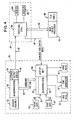
- FIG. 4 there is shown a more detailed block diagram of the checkout system of the present invention.
- Forward movement of a merchandise item 52 (Fig. 2) on the supporting surface 38 of the checkout counter 40 will trip the enter item gate 58 by intercepting the light beams directed from the light source 60, thereby generating the control signal IGE from the photodiode 58 over line 78 to a display microprocessor 80 located in the customer display member 61 (Fig. 2) of the scanner apparatus 20.
- the scanner apparatus 20 of the present invention shown within the dotted lines in Fig.
- the scanner assembly 40 includes the scanner assembly 30, a scanner microprocessor 82 for checking and decoding the encoded data read by the scanner assembly 30, a conventional memory storage unit 84, and an output buffer unit 86fortransmitting the data read by the scanner assembly 30 over line 87 which is part of the bus 22 (Fig. 1) and which is coupled to a processor unit (CPU) 88 located in the data terminal device 24.
- the processor unit 88 may comprise an Intel 4004 which is commercially available from the Intel Corporation of Santa Clara, California.
- the control signal IGE appearing on line 78 is transmitted to the microprocessor 80 in the customer display member 61 (Figs. 2 and 4) and then over bus 94 to the microprocessor 82.
- the microprocessor 82 in response receiving the signal IGE will turn on the light source 32 (Fig. 2) in the scanner assembly 30.
- the scanner assembly 30 will then read the label 50 on a merchandise item 52 which is positioned adjacent the aperture 36 and transmits the serial data read to the microprocessor 82.
- the data will be transmitted to the output buffer 86 preparatory for transmission over line 87 of the bus 22 (Fig. 1) to the processor 88 in the data terminal device 24.
- the processor 88 will encode the received serial data in Manchester code and will transmit the encoded data over bus 26 to the back office processor 28 which, using this data as an address, will access a price look-up table (PLU) 96 for retrieving the price of the merchandise item 52 being scanned.
- PLU price look-up table
- the table resides in RAM memory in the processor 28.
- the numerical data representing the price of the purchased item 52 is then transmitted over bus 26 to the processor 88 which in turn decodes the Manchester encoded data.
- the resulting numeric serial data is then transmitted over line 98 of the bus 26 to the microprocessor 80 which controls the display member 68 (Fig. 2) for displaying the price of the purchased item to the customer.
- the counter 100 will have stored therein a predetermined count and will be enabled, upon the generation of the signal IGE, to count down to 0 in a manner that is well known in the art, the count representing a time-out period which is used in determining a valid read operation by the scanner assembly 30 in a manner that will be described more fully hereinafter.
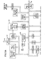
- the microprocessor 80 also includes a plurality of storage registers 102 (Fig. 5B) for temporarily storing the signal IGE generated by the enter item gate 58 (Fig. 4) and the signal IGL generated by the exit gate 64.
- the control of the microprocessor is found in the software program stored in the EPROM/ROM 104 (Fig. 5A).
- FIG. 6 there is disclosed a flow diagram illustrating the events that occur in the operation of the scanner system 20 (Fig. 1).
- the microprocessor 82 Prior to the movement of the merchandise item 52 (Fig. 2) past the scanner assembly 30, the microprocessor 82 (Figs. 4, 5A and 5B) is in an idle state which requires the enter item gate 58 to be tripped in order to initiate a scanning operation. If the operator at this time moves the merchandise item past the aperture 36 (Fig. 2) in the counter surface 38 of the checkout counter 40 without tripping the enter item gate 58, but trips the exit item gate 64 or moves the item 52 in the reverse direction, thereby tripping the exit item gate 64 first, the system will remain in the idle state and cycles between blocks 106 and 108.
- the signal is transmitted over line 78 (Fig. 4) through the microprocessor 80 and over the bus 94 to the microprocessor 82.
- the microprocessor 82 under the control of the program stored in the PROM/ ROM 104 (Fig. 5A) will generate the appropriate signals to turn on the laser light source 32 (Fig. 2) (Block 110) and enable the counter 100 (Block 112) in the microprocessor 82 (Fig. 5A) to start the countdown for generating the time-out sequence.
- the microprocessor 82 receives the encoded data read by the scanner assembly 30 and initiates a checking and decoding sequence if the data read is determined to be valid (Block 114). If the read operation produces a good read, the microprocessor 82 will turn off the light source 32 (Block 116) and check to see if the exit gate 64 has been tripped (Block 118). If it has been tripped, the microprocessor 82 will check to see if the output buffer 86 (Fig. 4) is available to receive data (Block 120). If it is available, the microprocessor 82 will transmit the good read signal GOOD over bus 94 to the microprocessor 80 in the customer display member 61 (Figs.
- the microprocessor 82 will also transfer the data read to the buffer 86 for transmission over line 87 to the processor 88 (Fig. 4) in the data terminal device 24.
- the microprocessor 82 Upon the returning of the enter item gate 58 (Fig. 4) to its clear condition (Block 126), the microprocessor 82 will return to an idle state preparatory to another scanning operation.
- the microprocessor 82 will check the exit item gate 64 (Fig. 4) (Block 128) to see if it has been tripped. If it has not been tripped, the processor 82 will cycle through blocks 128, 130 and 114 until a good read has been determined (Block 114) or until the event counter 100 (Fig. 5A) has timed out (Block 130). If the time-out occurs first, the light source 32 will be turned off (Block 132), the bad read indicator light 70 (Fig. 4) is illuminated (Block 134) and the microprocessor 82 returns to wait for the next read operation.
- the microprocessor 82 will go through blocks 128, 136, 138 and 140 to turn off the scanner assembly 30 preparatory to another read operation.
- Fig. 7 there is disclosed a flow chart of the program stored in the EPROM/ROM 104 (Fig. 5A) of the microprocessor 80.
- the processor 88 When data is transferred from the output buffer 86 over line 87 to the processor 88 in the data terminal device 24, the processor 88 will encode the received data in Manchester code and transmit the data over bus 26 to the back office processor 28 (Fig. 4) which uses the data to address the table 96 in which is stored the price of the merchandise items being offered for sale.
- the processor 28 which may comprise NCR 8060 mini-computer and which is commercially available from the NCR Corporation of Dayton, Ohio, will retrieve the price of the purchased item using the encoded data received and transmit the Manchester encoded price data to the processor 88 in the terminal device 24.
- the processor 88 will decode the received price data and transmit the numeric data representing the price of the purchased item over line 98 to the customer display member 68 where the price of the item is displayed.
- the price is also displayed in the terminal display 143 (Fig. 4) and also printed on a record member by the terminal printer 144.
- a terminal error signal in the form of binary bits is generated by the processor 88 and transmitted over line 98 (Fig. 4) as status data to the microprocessor 80 in the display member 61 (Fig. 2). If the price of the purchased item is not listed in the PLU table 96, a Not-on-File error is generated by the processor 28 as part of the status data which is transmitted through the processor 88 and over line 98 to the microprocessor 80.
- the microprocessor 80 at this time, after the system has been initialized (Block 145), will be checking (Block 146) the port bus buffer 147 (Fig. 5A) coupled to the line 98 (Fig. 4) of the bus 22 (Fig. 1) to detect the presence of any numeric data transmitted from the terminal 24 which represents the price of the purchased item. If the numeric data is present, it will enable the display member 68 to display the price (Block 148). If the numeric data is not present, it will check (Block 150) to see if there is present on line 98 status data transmitted from the terminal 24. If there is status data on line 98, the microprocessor 80 will check (Block 156) to see if the status data indicates an error condition at the terminal.
- the microprocessor 80 detects (Block 156) the presence of error status data on line 98, it will check the binary bits of the status data to determine if the error is a "Not-On-File" error (Block 158). If it is a "Not-On-File” error, the microprocessor cycles (Block 160) the tone generator 92 to generate a tone every 1/3 second, turns off the good read signal (Block 162), disabling the indicator member 72, and cycles the bad read indicator member 70 every 1/2 second (Block 162). The microprocessor 80 also disables (Block 164) the signals (IGE, IGL) generated by the item gates 58, 64 from being transmitted over the bus 94 (Fig.
- the microprocessor 80 will at this time check (Block 166) to see if there is still status data from the terminal appearing on line 98. If there is, the microprocessor 80 will again determine if the status data represents a "Not-On-File" error condition. If it does, the error indicator sequence described above is continued. If the error is not a "Not-On-File” error but comprises a terminal error such as a printer malfunction or other type of terminal error as described previously, the cycling of the bad read indicator member 70 (Block 162) will occur. Further, the scanner assembly is disabled (Block 164) in the manner described above.
Landscapes
- Physics & Mathematics (AREA)
- Business, Economics & Management (AREA)
- General Physics & Mathematics (AREA)
- Engineering & Computer Science (AREA)
- Accounting & Taxation (AREA)
- Theoretical Computer Science (AREA)
- Finance (AREA)
- Electromagnetism (AREA)
- Strategic Management (AREA)
- General Business, Economics & Management (AREA)
- Computer Vision & Pattern Recognition (AREA)
- Artificial Intelligence (AREA)
- Toxicology (AREA)
- General Health & Medical Sciences (AREA)
- Health & Medical Sciences (AREA)
- Computer Networks & Wireless Communication (AREA)
- Cash Registers Or Receiving Machines (AREA)
Claims (5)
Applications Claiming Priority (2)
| Application Number | Priority Date | Filing Date | Title |
|---|---|---|---|
| US06/753,076 US4679154A (en) | 1985-07-09 | 1985-07-09 | Scanning control system for merchandise checkout |
| US753076 | 1985-07-09 |
Publications (2)
| Publication Number | Publication Date |
|---|---|
| EP0230447A1 EP0230447A1 (de) | 1987-08-05 |
| EP0230447B1 true EP0230447B1 (de) | 1990-05-16 |
Family
ID=25029052
Family Applications (1)
| Application Number | Title | Priority Date | Filing Date |
|---|---|---|---|
| EP86904539A Expired EP0230447B1 (de) | 1985-07-09 | 1986-06-19 | Ausgabeüberwachungssystem |
Country Status (6)
| Country | Link |
|---|---|
| US (1) | US4679154A (de) |
| EP (1) | EP0230447B1 (de) |
| JP (1) | JPS63500130A (de) |
| CA (1) | CA1251281A (de) |
| DE (1) | DE3671308D1 (de) |
| WO (1) | WO1987000322A1 (de) |
Families Citing this family (55)
| Publication number | Priority date | Publication date | Assignee | Title |
|---|---|---|---|---|
| JPS62184596A (ja) * | 1986-02-10 | 1987-08-12 | オムロン株式会社 | 電子式キヤツシユレジスタ |
| US4860226A (en) * | 1986-09-09 | 1989-08-22 | Martin Edward L | Method and apparatus for bar code graphics quality control |
| US4875163A (en) * | 1986-09-22 | 1989-10-17 | Omron Tateisi Electronics Co. | Electronic cash register system with faster access time to price look-up file |
| JPH0789394B2 (ja) * | 1986-11-14 | 1995-09-27 | オムロン株式会社 | Pos端末装置 |
| US4751641A (en) * | 1986-12-22 | 1988-06-14 | Ncr Corporation | Method and apparatus for storing data to facilitate price look-up |
| US4775782A (en) * | 1987-09-30 | 1988-10-04 | Ncr Corporation | Checkout counter with remote keyboard writing pad and display |
| EP0348484B1 (de) * | 1987-12-28 | 1993-09-29 | Ncr International Inc. | Ausgangsrechnungsabwicklungssystem und -verfahren |
| JPH01173292A (ja) * | 1987-12-28 | 1989-07-07 | Ncr Corp | キヤツシヤレス・チエツクアウト・システム |
| US5448046A (en) * | 1987-12-28 | 1995-09-05 | Symbol Technologies, Inc. | Arrangement for and method of expediting commercial product transactions at a point-of-sale site |
| JPH01269197A (ja) * | 1988-04-21 | 1989-10-26 | Tokyo Electric Co Ltd | 電子キャッシュレジスタ |
| US4868375A (en) * | 1988-08-22 | 1989-09-19 | Ncr Corporation | Method for changing the functions of a bar code reader |
| US5229586A (en) * | 1988-10-28 | 1993-07-20 | Tokyo Electric Co., Ltd. | Card issuing apparatus having sequential processing units |
| US4991008A (en) * | 1988-12-01 | 1991-02-05 | Intec Video Systems, Inc. | Automatic transaction surveillance system |
| US5008518A (en) * | 1989-03-24 | 1991-04-16 | Spectra-Physics, Inc. | Data gathering system interface |
| US5162639A (en) * | 1989-06-30 | 1992-11-10 | Ncr Corporation | Method for updating price look up files in a point of sale terminal |
| US4967188A (en) * | 1989-07-26 | 1990-10-30 | Ncr Corporation | Method for detecting low battery voltage in portable scanning systems |
| US5144114A (en) * | 1989-09-15 | 1992-09-01 | Ncr Corporation | Volume control apparatus |
| US5023818A (en) * | 1989-09-21 | 1991-06-11 | Ncr Corporation | Laser scanner safety apparatus and method |
| US4968883A (en) * | 1989-10-20 | 1990-11-06 | Ncr Corporation | Apparatus and method for vertical mounting of an optical scanner |
| US5144118A (en) * | 1990-03-05 | 1992-09-01 | Spectra-Physics, Inc. | Bar code scanning system with multiple decoding microprocessors |
| US5247161A (en) * | 1990-03-05 | 1993-09-21 | Spectra-Physics, Inc. | Bar code scanning system with converter means and microprocessor means contained in a single integrated circuit |
| US5263164A (en) | 1991-01-09 | 1993-11-16 | Verifone, Inc. | Method and structure for determining transaction system hardware and software configurations |
| DE69224777T2 (de) * | 1991-07-19 | 1998-07-09 | Kabushiki Kaisha Tec, Shizuoka | Warenabrechnungsanlage |
| US5256863A (en) * | 1991-11-05 | 1993-10-26 | Comark Technologies, Inc. | In-store universal control system |
| US5604486A (en) * | 1993-05-27 | 1997-02-18 | Motorola, Inc. | RF tagging system with multiple decoding modalities |
| KR0159973B1 (ko) * | 1993-10-25 | 1998-12-15 | 구보 미쯔오 | 자체 스캐닝 검사 장치 |
| US6449377B1 (en) | 1995-05-08 | 2002-09-10 | Digimarc Corporation | Methods and systems for watermark processing of line art images |
| US7044395B1 (en) * | 1993-11-18 | 2006-05-16 | Digimarc Corporation | Embedding and reading imperceptible codes on objects |
| US6164535A (en) * | 1994-10-21 | 2000-12-26 | Ncr Corporation | Price maintenance system and method |
| US5939697A (en) * | 1996-04-29 | 1999-08-17 | Webscan, Inc. | Bar code evaluation system architectures and methods of calibration |
| US7555458B1 (en) | 1996-06-05 | 2009-06-30 | Fraud Control System.Com Corporation | Method of billing a purchase made over a computer network |
| US8229844B2 (en) | 1996-06-05 | 2012-07-24 | Fraud Control Systems.Com Corporation | Method of billing a purchase made over a computer network |
| US20030195848A1 (en) | 1996-06-05 | 2003-10-16 | David Felger | Method of billing a purchase made over a computer network |
| US5987426A (en) | 1997-10-14 | 1999-11-16 | Ncr Corporation | Point-of-sale system including isolation layer between client and server software |
| US6354498B1 (en) * | 1997-12-24 | 2002-03-12 | Ncr Corporation | Method for displaying the status of a self-service checkout terminal |
| US6830181B1 (en) * | 1998-02-09 | 2004-12-14 | Intermec Ip Corp. | Combined optical and radio frequency tag reader |
| US6369709B1 (en) | 1998-04-10 | 2002-04-09 | 3M Innovative Properties Company | Terminal for libraries and the like |
| US5967264A (en) | 1998-05-01 | 1999-10-19 | Ncr Corporation | Method of monitoring item shuffling in a post-scan area of a self-service checkout terminal |
| US6497361B1 (en) * | 1998-10-15 | 2002-12-24 | Ncr Corporation | Apparatus and method for deactivating electronic article surveillance in a retail self-checkout terminal |
| US6325290B1 (en) * | 1998-12-04 | 2001-12-04 | Ncr Corporation | Method and apparatus for checking out large items with a self-service checkout terminal |
| US6856964B1 (en) | 1999-03-22 | 2005-02-15 | Ncr Corporation | System and methods for integrating a self-checkout system into an existing store system |
| US6296185B1 (en) | 1999-11-02 | 2001-10-02 | Ncr Corporation | Apparatus and method for operating a checkout system having a display monitor which displays both transaction information and customer-specific messages during a checkout transaction |
| US6880755B2 (en) * | 1999-12-06 | 2005-04-19 | Xerox Coporation | Method and apparatus for display of spatially registered information using embedded data |
| US6899273B2 (en) * | 2001-05-02 | 2005-05-31 | Hand Held Products, Inc. | Optical reader comprising soft key including permanent graphic indicia |
| US6817530B2 (en) | 2001-12-18 | 2004-11-16 | Digimarc Id Systems | Multiple image security features for identification documents and methods of making same |
| US7824029B2 (en) | 2002-05-10 | 2010-11-02 | L-1 Secure Credentialing, Inc. | Identification card printer-assembler for over the counter card issuing |
| US20080208696A1 (en) * | 2007-02-26 | 2008-08-28 | Quentin Olson | Point of sale system with web-based back-office |
| US8282002B2 (en) * | 2010-03-08 | 2012-10-09 | Apple Inc. | Multi-barcode scan process |
| US9189669B2 (en) | 2010-06-24 | 2015-11-17 | Metrologic Instruments, Inc. | Distinctive notice for different symbology information |
| US9589164B2 (en) | 2010-06-24 | 2017-03-07 | Metrologic Instruments, Inc. | Distinctive notice for different symbology information |
| US9082142B2 (en) * | 2012-01-09 | 2015-07-14 | Datalogic ADC, Inc. | Using a mobile device to assist in exception handling in self-checkout and automated data capture systems |
| US9378397B2 (en) | 2012-07-18 | 2016-06-28 | Datalogic ADC, Inc. | Portal data reader indicator light control |
| US9607486B2 (en) * | 2013-01-29 | 2017-03-28 | Wal-Mart Stores, Inc. | Shopping process including monitored shopping cart basket weight |
| US10430776B2 (en) | 2014-01-09 | 2019-10-01 | Datalogic Usa, Inc. | System and method for exception handling in self-checkout and automated data capture systems |
| US10055626B2 (en) | 2016-12-06 | 2018-08-21 | Datalogic Usa, Inc. | Data reading system and method with user feedback for improved exception handling and item modeling |
Family Cites Families (6)
| Publication number | Priority date | Publication date | Assignee | Title |
|---|---|---|---|---|
| US3819012A (en) * | 1970-03-20 | 1974-06-25 | Rca Corp | Merchandise handling and identifying system |
| US4086476A (en) * | 1976-07-29 | 1978-04-25 | Ncr Corporation | Control circuit for a code reading device |
| US4266271A (en) * | 1978-10-10 | 1981-05-05 | Chamoff Martin E | Reconfigurable cluster of data-entry terminals |
| US4204636A (en) * | 1978-10-13 | 1980-05-27 | Stanley Hayman and Company | Interface between data reading wand and cash register display |
| US4529871A (en) * | 1982-09-29 | 1985-07-16 | Loblaw Companies Limited | Price marking system |
| US4554446A (en) * | 1983-11-18 | 1985-11-19 | Murphy Arthur J | Supermarket inventory control system and method |
-
1985
- 1985-07-09 US US06/753,076 patent/US4679154A/en not_active Expired - Lifetime
-
1986
- 1986-04-30 CA CA000507989A patent/CA1251281A/en not_active Expired
- 1986-06-19 DE DE8686904539T patent/DE3671308D1/de not_active Expired - Lifetime
- 1986-06-19 WO PCT/US1986/001321 patent/WO1987000322A1/en not_active Ceased
- 1986-06-19 EP EP86904539A patent/EP0230447B1/de not_active Expired
- 1986-06-19 JP JP61503644A patent/JPS63500130A/ja active Pending
Also Published As
| Publication number | Publication date |
|---|---|
| JPS63500130A (ja) | 1988-01-14 |
| EP0230447A1 (de) | 1987-08-05 |
| WO1987000322A1 (en) | 1987-01-15 |
| CA1251281A (en) | 1989-03-14 |
| DE3671308D1 (de) | 1990-06-21 |
| US4679154A (en) | 1987-07-07 |
Similar Documents
| Publication | Publication Date | Title |
|---|---|---|
| EP0230447B1 (de) | Ausgabeüberwachungssystem | |
| US4086476A (en) | Control circuit for a code reading device | |
| US6080938A (en) | Method and apparatus for resetting a product scale of a retail checkout terminal | |
| US5019694A (en) | Overhead scanning terminal | |
| US6543683B2 (en) | System and method for providing consumer access to a stored digital receipt generated as a result of a purchase transaction and to business/consumer applications related to the stored digital receipt | |
| US5139100A (en) | Point-of-sale scanner/scale system with scale activation of scanner | |
| EP0448386A2 (de) | Vorrichtung und Verfahren für Lotterie und Verkaufsstellen-Handelsgeschäfte | |
| US5237163A (en) | Method for scanning a plurality of bar code labels | |
| US4575623A (en) | Optical code scanner and display | |
| US4204636A (en) | Interface between data reading wand and cash register display | |
| US5138141A (en) | Method and apparatus for repeating the output of an optical scanner | |
| US5196686A (en) | Checkout system with inlaid checkout counter keypad | |
| US6488207B1 (en) | Bar code reader, scaling device and scaling method | |
| EP2447921A1 (de) | Verkaufsstellenendgerät | |
| JP2001005905A (ja) | コードリーダ検査装置及び商品販売登録データ処理装置 | |
| EP0429259A1 (de) | Kassentisch mit einem Tastenfeld | |
| JP2836773B2 (ja) | バーコードデータ検出方法及び装置 | |
| JPH03238573A (ja) | バーコードラベル読取装置 | |
| JPS6086661A (ja) | デ−タ読取方式 | |
| JPH0421231B2 (de) | ||
| JPH0962942A (ja) | 電子式キャッシュレジスタ | |
| JPS60160480A (ja) | 光学読取装置 | |
| JP3501628B2 (ja) | Posターミナル | |
| KR910004528B1 (ko) | 금전등록기의 쿠폰 발행 방식 | |
| JPS5913382B2 (ja) | 手持ち型ラベラ− |
Legal Events
| Date | Code | Title | Description |
|---|---|---|---|
| PUAI | Public reference made under article 153(3) epc to a published international application that has entered the european phase |
Free format text: ORIGINAL CODE: 0009012 |
|
| AK | Designated contracting states |
Kind code of ref document: A1 Designated state(s): DE FR GB |
|
| 17P | Request for examination filed |
Effective date: 19870629 |
|
| DET | De: translation of patent claims | ||
| 17Q | First examination report despatched |
Effective date: 19881229 |
|
| GRAA | (expected) grant |
Free format text: ORIGINAL CODE: 0009210 |
|
| AK | Designated contracting states |
Kind code of ref document: B1 Designated state(s): DE FR GB |
|
| REF | Corresponds to: |
Ref document number: 3671308 Country of ref document: DE Date of ref document: 19900621 |
|
| ET | Fr: translation filed | ||
| PLBE | No opposition filed within time limit |
Free format text: ORIGINAL CODE: 0009261 |
|
| STAA | Information on the status of an ep patent application or granted ep patent |
Free format text: STATUS: NO OPPOSITION FILED WITHIN TIME LIMIT |
|
| 26N | No opposition filed | ||
| PGFP | Annual fee paid to national office [announced via postgrant information from national office to epo] |
Ref country code: FR Payment date: 19920327 Year of fee payment: 7 |
|
| PGFP | Annual fee paid to national office [announced via postgrant information from national office to epo] |
Ref country code: GB Payment date: 19920401 Year of fee payment: 7 |
|
| PGFP | Annual fee paid to national office [announced via postgrant information from national office to epo] |
Ref country code: DE Payment date: 19920629 Year of fee payment: 7 |
|
| REG | Reference to a national code |
Ref country code: GB Ref legal event code: 732E |
|
| REG | Reference to a national code |
Ref country code: FR Ref legal event code: TP |
|
| PG25 | Lapsed in a contracting state [announced via postgrant information from national office to epo] |
Ref country code: GB Effective date: 19930619 |
|
| GBPC | Gb: european patent ceased through non-payment of renewal fee |
Effective date: 19930619 |
|
| PG25 | Lapsed in a contracting state [announced via postgrant information from national office to epo] |
Ref country code: FR Effective date: 19940228 |
|
| PG25 | Lapsed in a contracting state [announced via postgrant information from national office to epo] |
Ref country code: DE Effective date: 19940301 |
|
| REG | Reference to a national code |
Ref country code: FR Ref legal event code: ST |