EP0230579A1 - Filtre de particules pour des gaz d'échappement - Google Patents
Filtre de particules pour des gaz d'échappement Download PDFInfo
- Publication number
- EP0230579A1 EP0230579A1 EP86116939A EP86116939A EP0230579A1 EP 0230579 A1 EP0230579 A1 EP 0230579A1 EP 86116939 A EP86116939 A EP 86116939A EP 86116939 A EP86116939 A EP 86116939A EP 0230579 A1 EP0230579 A1 EP 0230579A1
- Authority
- EP
- European Patent Office
- Prior art keywords
- fibers
- filter
- winding
- wound
- auxiliary
- Prior art date
- Legal status (The legal status is an assumption and is not a legal conclusion. Google has not performed a legal analysis and makes no representation as to the accuracy of the status listed.)
- Withdrawn
Links
Images


Classifications
-
- B—PERFORMING OPERATIONS; TRANSPORTING
- B29—WORKING OF PLASTICS; WORKING OF SUBSTANCES IN A PLASTIC STATE IN GENERAL
- B29C—SHAPING OR JOINING OF PLASTICS; SHAPING OF MATERIAL IN A PLASTIC STATE, NOT OTHERWISE PROVIDED FOR; AFTER-TREATMENT OF THE SHAPED PRODUCTS, e.g. REPAIRING
- B29C53/00—Shaping by bending, folding, twisting, straightening or flattening; Apparatus therefor
- B29C53/56—Winding and joining, e.g. winding spirally
- B29C53/58—Winding and joining, e.g. winding spirally helically
- B29C53/583—Winding and joining, e.g. winding spirally helically for making tubular articles with particular features
- B29C53/587—Winding and joining, e.g. winding spirally helically for making tubular articles with particular features having a non-uniform wall-structure, e.g. with inserts, perforations, locally concentrated reinforcements
-
- B—PERFORMING OPERATIONS; TRANSPORTING
- B01—PHYSICAL OR CHEMICAL PROCESSES OR APPARATUS IN GENERAL
- B01D—SEPARATION
- B01D39/00—Filtering material for liquid or gaseous fluids
- B01D39/14—Other self-supporting filtering material ; Other filtering material
- B01D39/20—Other self-supporting filtering material ; Other filtering material of inorganic material, e.g. asbestos paper, metallic filtering material of non-woven wires
- B01D39/2003—Glass or glassy material
- B01D39/2017—Glass or glassy material the material being filamentary or fibrous
-
- B—PERFORMING OPERATIONS; TRANSPORTING
- B01—PHYSICAL OR CHEMICAL PROCESSES OR APPARATUS IN GENERAL
- B01D—SEPARATION
- B01D39/00—Filtering material for liquid or gaseous fluids
- B01D39/14—Other self-supporting filtering material ; Other filtering material
- B01D39/20—Other self-supporting filtering material ; Other filtering material of inorganic material, e.g. asbestos paper, metallic filtering material of non-woven wires
- B01D39/2027—Metallic material
- B01D39/2041—Metallic material the material being filamentary or fibrous
-
- B—PERFORMING OPERATIONS; TRANSPORTING
- B01—PHYSICAL OR CHEMICAL PROCESSES OR APPARATUS IN GENERAL
- B01D—SEPARATION
- B01D39/00—Filtering material for liquid or gaseous fluids
- B01D39/14—Other self-supporting filtering material ; Other filtering material
- B01D39/20—Other self-supporting filtering material ; Other filtering material of inorganic material, e.g. asbestos paper, metallic filtering material of non-woven wires
- B01D39/2068—Other inorganic materials, e.g. ceramics
- B01D39/2082—Other inorganic materials, e.g. ceramics the material being filamentary or fibrous
-
- B—PERFORMING OPERATIONS; TRANSPORTING
- B01—PHYSICAL OR CHEMICAL PROCESSES OR APPARATUS IN GENERAL
- B01D—SEPARATION
- B01D46/00—Filters or filtering processes specially modified for separating dispersed particles from gases or vapours
- B01D46/24—Particle separators, e.g. dust precipitators, using rigid hollow filter bodies
-
- B—PERFORMING OPERATIONS; TRANSPORTING
- B29—WORKING OF PLASTICS; WORKING OF SUBSTANCES IN A PLASTIC STATE IN GENERAL
- B29C—SHAPING OR JOINING OF PLASTICS; SHAPING OF MATERIAL IN A PLASTIC STATE, NOT OTHERWISE PROVIDED FOR; AFTER-TREATMENT OF THE SHAPED PRODUCTS, e.g. REPAIRING
- B29C70/00—Shaping composites, i.e. plastics material comprising reinforcements, fillers or preformed parts, e.g. inserts
- B29C70/04—Shaping composites, i.e. plastics material comprising reinforcements, fillers or preformed parts, e.g. inserts comprising reinforcements only, e.g. self-reinforcing plastics
- B29C70/06—Fibrous reinforcements only
- B29C70/10—Fibrous reinforcements only characterised by the structure of fibrous reinforcements, e.g. hollow fibres
- B29C70/16—Fibrous reinforcements only characterised by the structure of fibrous reinforcements, e.g. hollow fibres using fibres of substantial or continuous length
- B29C70/20—Fibrous reinforcements only characterised by the structure of fibrous reinforcements, e.g. hollow fibres using fibres of substantial or continuous length oriented in a single direction, e.g. roofing or other parallel fibres
- B29C70/205—Fibrous reinforcements only characterised by the structure of fibrous reinforcements, e.g. hollow fibres using fibres of substantial or continuous length oriented in a single direction, e.g. roofing or other parallel fibres the structure being shaped to form a three-dimensional configuration
- B29C70/207—Fibrous reinforcements only characterised by the structure of fibrous reinforcements, e.g. hollow fibres using fibres of substantial or continuous length oriented in a single direction, e.g. roofing or other parallel fibres the structure being shaped to form a three-dimensional configuration arranged in parallel planes of fibres crossing at substantial angles
-
- F—MECHANICAL ENGINEERING; LIGHTING; HEATING; WEAPONS; BLASTING
- F01—MACHINES OR ENGINES IN GENERAL; ENGINE PLANTS IN GENERAL; STEAM ENGINES
- F01N—GAS-FLOW SILENCERS OR EXHAUST APPARATUS FOR MACHINES OR ENGINES IN GENERAL; GAS-FLOW SILENCERS OR EXHAUST APPARATUS FOR INTERNAL-COMBUSTION ENGINES
- F01N3/00—Exhaust or silencing apparatus having means for purifying, rendering innocuous, or otherwise treating exhaust
- F01N3/02—Exhaust or silencing apparatus having means for purifying, rendering innocuous, or otherwise treating exhaust for cooling, or for removing solid constituents of, exhaust
- F01N3/021—Exhaust or silencing apparatus having means for purifying, rendering innocuous, or otherwise treating exhaust for cooling, or for removing solid constituents of, exhaust by means of filters
- F01N3/022—Exhaust or silencing apparatus having means for purifying, rendering innocuous, or otherwise treating exhaust for cooling, or for removing solid constituents of, exhaust by means of filters characterised by specially adapted filtering structure, e.g. honeycomb, mesh or fibrous
- F01N3/0226—Exhaust or silencing apparatus having means for purifying, rendering innocuous, or otherwise treating exhaust for cooling, or for removing solid constituents of, exhaust by means of filters characterised by specially adapted filtering structure, e.g. honeycomb, mesh or fibrous the structure being fibrous
-
- B—PERFORMING OPERATIONS; TRANSPORTING
- B01—PHYSICAL OR CHEMICAL PROCESSES OR APPARATUS IN GENERAL
- B01D—SEPARATION
- B01D2239/00—Aspects relating to filtering material for liquid or gaseous fluids
- B01D2239/06—Filter cloth, e.g. knitted, woven non-woven; self-supported material
- B01D2239/0604—Arrangement of the fibres in the filtering material
- B01D2239/0636—Two or more types of fibres present in the filter material
-
- B—PERFORMING OPERATIONS; TRANSPORTING
- B01—PHYSICAL OR CHEMICAL PROCESSES OR APPARATUS IN GENERAL
- B01D—SEPARATION
- B01D2239/00—Aspects relating to filtering material for liquid or gaseous fluids
- B01D2239/06—Filter cloth, e.g. knitted, woven non-woven; self-supported material
- B01D2239/065—More than one layer present in the filtering material
-
- B—PERFORMING OPERATIONS; TRANSPORTING
- B01—PHYSICAL OR CHEMICAL PROCESSES OR APPARATUS IN GENERAL
- B01D—SEPARATION
- B01D2239/00—Aspects relating to filtering material for liquid or gaseous fluids
- B01D2239/06—Filter cloth, e.g. knitted, woven non-woven; self-supported material
- B01D2239/069—Special geometry of layers
- B01D2239/0695—Wound layers
-
- B—PERFORMING OPERATIONS; TRANSPORTING
- B29—WORKING OF PLASTICS; WORKING OF SUBSTANCES IN A PLASTIC STATE IN GENERAL
- B29L—INDEXING SCHEME ASSOCIATED WITH SUBCLASS B29C, RELATING TO PARTICULAR ARTICLES
- B29L2031/00—Other particular articles
- B29L2031/14—Filters
-
- Y—GENERAL TAGGING OF NEW TECHNOLOGICAL DEVELOPMENTS; GENERAL TAGGING OF CROSS-SECTIONAL TECHNOLOGIES SPANNING OVER SEVERAL SECTIONS OF THE IPC; TECHNICAL SUBJECTS COVERED BY FORMER USPC CROSS-REFERENCE ART COLLECTIONS [XRACs] AND DIGESTS
- Y02—TECHNOLOGIES OR APPLICATIONS FOR MITIGATION OR ADAPTATION AGAINST CLIMATE CHANGE
- Y02T—CLIMATE CHANGE MITIGATION TECHNOLOGIES RELATED TO TRANSPORTATION
- Y02T10/00—Road transport of goods or passengers
- Y02T10/10—Internal combustion engine [ICE] based vehicles
- Y02T10/12—Improving ICE efficiencies
Definitions
- the invention relates to a particle filter for exhaust gases, consisting of a winding body made of temperature-resistant fibers.
- the various filter constructions such as ceramic foam, fiber mats, wire mesh and as a winding body
- the latter have the advantage over the previous variants that the ratio of the filter size to the filter effect is more favorable, i.e. is lower than with filters of other constructions.
- the invention has for its object to improve a filter of the type mentioned in such a way that the filter effect of the filter material can be used as fully as possible.
- part of the fibers namely the auxiliary fibers, serves, in addition to the function as a filter, as a framework for the winding body, so that support bodies can be dispensed with. This eliminates any impairment of the degree of separation of the filter.
- a homogeneous structure that can be achieved in this way creates a homogeneous flow field during operation, which enables the particles to be deposited evenly through the entire filter.
- Another advantage of the filter according to the invention is that a uniform filter can be produced, which can be flowed through either in one direction or in the other direction as required.
- the basic fibers can be rovings or yarns made of ceramic, quartz, silicon, glass or similar temperature-resistant materials, the filaments of the rovings or yarns being able to have extremely small cross sections, so that the effective area of the filter can be increased by the choice correspondingly thin filaments can be effected.
- the filaments of the basic fibers preferably have a diameter of at most 10 ⁇ m, preferably less than 7 ⁇ m.
- Steel wire which has a diameter of 0.1 to 0.7 mm depending on the type of use or the quantity ratio in the filter body, can preferably be used as the auxiliary fiber.
- the wire thickness is inversely proportional to the ratio of the amount of wire to the amount of basic fibers in the filter body.
- the basic fibers and the auxiliary fibers can be combined according to different patterns.
- the filter body consisting essentially of basic fibers is mixed with the auxiliary fibers.
- This can be done by winding the auxiliary fibers together with the basic fibers in one operation, in which, depending on the desired quantitative ratio, an auxiliary fiber and several basic fiber strands are wound simultaneously.
- the auxiliary fibers are located essentially on the surfaces of the filter body, predominantly basic fibers being provided between the two layers of auxiliary fibers.
- the auxiliary fibers can either be wound or used in the form of a network.
- This embodiment has the advantage that the auxiliary fibers anchor the basic fibers, which can tear at least on the surface because of their reduced cross-section and possibly because of their porosity.
- the required stiffness is determined by appropriate selection of the quantity or the thickness of the auxiliary fibers introduced in such a way that the filter body, which consists solely of basic fibers and auxiliary fibers, on its own, i.e. is operational without support elements.
- the auxiliary fibers are an integral part of the filter body or the filter material.
- the filter according to the invention can take on any geometric shape that can be produced in the winding process. It is thus possible to design the filter in the form of a plate as well as a tube.
- the fibers in the winding body are wound in an intersecting manner, it being possible, in particular by using an open winding process, to create spaces between fiber strands which give the winding body the porosity required for the flow and deflection of the gas to be cleaned.
- the particles can flow partially through different layers and within the Deposit the winding body, whereby a depth filter effect is achieved.
- This effect can be intensified by measures which reduce the knotting of crossing fiber or yarn strands. It is also advantageous if at least the basic fibers are loosely guided when the filter is being wound in order to introduce a corresponding porosity into the filter, which brings about a depth filter effect.
- the invention extends to a method for producing a particle filter, which is characterized by the features of claims 12-14.
- Fiber strands are to be understood as the basic fibers and the auxiliary fibers.
- gaps are provided which allow particles with the gas to penetrate into the inner regions of the filter. In this way, not only the surface, but the entire filter volume acts as a deposit area for the particles contained in the gas.
- the gaps must be designed so that the exhaust gases undergo multiple deflections and in this way particles that have not been held on the surface or the first layers can be retained in deeper layers.
- the porosity is preferably achieved by simultaneously winding a plurality of fiber strands which are wound in cross layers at a distance from one another.
- the fibers of a next layer are laid over several fibers of the previous layer without creating nodes.
- This has the advantage that an intermediate layer is the two adjacent ones can separate fiber layers crossing at a distance that corresponds approximately to the fiber strand thickness.
- This is achieved in a technically simple manner by using a ring thread eye.
- the number of fiber strands guided with the ring thread eye depends on the diameter of the winding former and on the desired distance between the fiber strands.
- Each winding layer will consist exclusively of fibers lying next to each other, ie without knots.
- the fibers of different layers with the same orientation are wound on the hatch to avoid pore channels that run straight through the winding body wall. This creates zigzag channels through which the gas can flow with particles and particles can accumulate again and again.
- a plurality of filters can be wound in one operation by winding a correspondingly long filter body and separating them into the filter bodies one after the other. Working time and material loss are reduced.
- the fiber strands can be rovings combined from many thin filaments, the cross section of an filament being preferably less than 10 ⁇ m thick.
- Such a fiber strand has the advantage that the deposition area for the particles is greatly increased by the large number of very thin filaments. Their effect is particularly noticeable when the fiber is loosely wound so that the gas with small particles can also flow through fiber strands. In this regard, a larger diameter is also advantageous for tubular filters.
- auxiliary fibers are wound with the other fibers, so that the filter body is evenly interspersed with auxiliary fibers.
- the auxiliary fiber winding or network also serves as filter material on which the particles can be deposited, just like with the other fibers.
- the filter bodies can be wound using any method known in winding technology.
- 1 shows, for example, a thread eye (10) with three fiber strands (11) arranged next to one another, which are wound around a mandrel (12) rotating about the axis.
- the fiber strands (11) are each held at intervals (13) so that a width (14) is coated per winding which is greater than the sum of the diameters of the three fibers.
- the first winding layer (15) is placed approximately at an angle of 60 °.
- a second layer is laid crosswise at minus 60 °.
- a third layer can then in turn receive a different orientation that does not correspond to either the first or the second layer. If the third layer is also to be laid at 60 ° like the first layer, then the fiber strands are placed on the hatch in relation to the previous layer of the same orientation on the hatch, as shown in broken lines under the reference number (16).
- FIG. 2 The result of such a winding pattern is shown in FIG. 2 as a greatly enlarged detail, the fibers of different orientations being drawn at right angles to simplify the illustration.
- the fibers (20) wound at a distance and on the hatch form pore chambers (21), all of which are connected to one another, but do not form any openings crossing the filter wall in a straight line.
- An exhaust gas stream (22) is therefore guided in a zigzag fashion within these chambers (21) or channels, which on the one hand are large enough to let the particles in the gas (22) pass and on the other hand are small enough to allow these particles to pass through the filter (23) with the To be able to hold fibers (20).
- the effective filtering surface thus extends to the surface of all fiber strands (11 or 20) of the filter body.
- a fiber strand (11) consists of several filaments (18) which are bundled together to form a fiber strand or roving (11).
- the fiber strands (20) consist of filaments (24) twisted into a yarn.
- FIG 3 shows an example in which a tubular filter (39) is wound using a ring thread eye (30).
- the ring thread eye (30) has six bores (31), through each of which a fiber strand (32) is guided, which are guided over castors (33).
- the number of fiber strands (32) to be wound together depends on the desired distance (13, FIG. 1) between the fiber strands (32) on the winding body (39) and the diameter of the winding body (39).
- the mandrel consists of a mandrel core (37) around which sleeve segments (38) are placed.
- the fiber strands (32) are wound onto the sleeve segments (38) by rotating the mandrel (37, 38) in the direction of the arrow and displacing the ring thread eye (30) in the axial direction.
- the winding angle is determined via the resulting speed, which results from the combination of the speed of rotation of the mandrel and the feed of the thread eye.
- the angles are chosen so that the fibers of each layer cross with the fibers of the adjacent fibers.
- Another parameter to consider is the fiber draw during the winding process.
- FIG. 4 shows a plate-shaped filter (100) designed as a winding body and shown in cross section, which consists of basic fibers (110 and 120) made of ceramic, glass or similar temperature-resistant material and of auxiliary fibers (130) made of steel or another temperature-resistant metal .
- the basic fibers (110 and 120) are fiber strands, each of which contains several filaments (140) with a very small diameter in the range of a few ⁇ m.
- the filaments (140) can be arranged parallel to each other to form a roving or twisted to form a yarn.
- the auxiliary fibers (130) are metal wires which are coiled during the winding process of the basic fibers (110 and 120) and thereby penetrate the filter (100) in all layers.
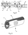
- the formation of the pore chambers can be illustrated using FIG. 5.
- the basic fiber strands (110 and 120) are yarns spun from filaments (140).
- three basic fibers are wound simultaneously in the winding process so that they come to lie next to one another with the appropriate spacing (150).
- the transverse base fibers (120) each lie in the different layers on the longitudinal fibers (110) and form pore chambers (200), as shown in the left half of FIG. 5. In transition areas (210) there is a change of position between fibers of different orientations.
- knots (210) the fiber spacings of different layers are reduced, so that the formation of pore chambers is effectively prevented. It is therefore advisable to run as many fibers as possible in the winding process in order to reduce the nodes (210).
- the exhaust gas (220) flows through the loose meshwork with numerous deflections and in part carries the particles with it into the interior of the filter (100).
- the particles meet fibers (110 to 130) one after the other and are deposited there.
- the filtration is therefore not carried out on the surface of the filter, but rather total volume or the sum of the surfaces of the fibers (110 to 130) or the filaments (140) contributes to the filtration of the gas particles.
- the basic fibers (110 and 120) make up the major part of the filter effect, they are wound in a symmetrical form, while the auxiliary fibers (130) are placed within the gaps (150).
- auxiliary fibers (130) in the filter There are many ways to integrate the auxiliary fibers (130) in the filter. These can be integrated homogeneously in the winding body or can also be attached to a greater extent in a filter plane or on the surfaces of the filter.
- FIG. 6 shows an embodiment in the case of a tubular filter (101) in which the auxiliary fibers (131) are arranged on the inner circumference and on the outer circumference of the tubular body, while the inner region of the filter tube (101) contains only basic fibers (111, 121).
- the auxiliary fibers (131) are processed into networks (300) according to FIG. 6.
- the auxiliary fibers on the outer circumference serve not only as filter material and to stiffen the winding body, but also to protect and anchor the surface base fibers. Particularly in the case of brittle and very thin base fibers (111, 121), these can easily tear due to handling etc., in particular on the surface of the winding body.
- peripheral auxiliary fibers (131), which can also be wound, do not represent a barrier, but rather a filter part. If necessary, additional fibers can be provided in the basic fiber winding body, for example in the manner shown in FIG. 4.
- Filters of the type described here are direction-independent, so that a uniform filter can be produced for both gas flow directions.
- the filter effect is, for example, the same, regardless of whether the gas is directed from the inside to the outside or from the outside to the inside of the filter tube (101).
Landscapes
- Chemical & Material Sciences (AREA)
- Engineering & Computer Science (AREA)
- Chemical Kinetics & Catalysis (AREA)
- Geology (AREA)
- Mechanical Engineering (AREA)
- Life Sciences & Earth Sciences (AREA)
- Ceramic Engineering (AREA)
- Inorganic Chemistry (AREA)
- Textile Engineering (AREA)
- Composite Materials (AREA)
- Combustion & Propulsion (AREA)
- General Engineering & Computer Science (AREA)
- Filtering Materials (AREA)
Applications Claiming Priority (4)
| Application Number | Priority Date | Filing Date | Title |
|---|---|---|---|
| DE3602153 | 1986-01-24 | ||
| DE19863602154 DE3602154A1 (de) | 1986-01-24 | 1986-01-24 | Partikelfilter fuer abgase |
| DE19863602153 DE3602153A1 (de) | 1986-01-24 | 1986-01-24 | Verfahren zum wickeln von partikelfiltern |
| DE3602154 | 1986-01-24 |
Publications (1)
| Publication Number | Publication Date |
|---|---|
| EP0230579A1 true EP0230579A1 (fr) | 1987-08-05 |
Family
ID=25840413
Family Applications (1)
| Application Number | Title | Priority Date | Filing Date |
|---|---|---|---|
| EP86116939A Withdrawn EP0230579A1 (fr) | 1986-01-24 | 1986-12-05 | Filtre de particules pour des gaz d'échappement |
Country Status (1)
| Country | Link |
|---|---|
| EP (1) | EP0230579A1 (fr) |
Cited By (3)
| Publication number | Priority date | Publication date | Assignee | Title |
|---|---|---|---|---|
| WO1989002976A1 (fr) * | 1987-09-22 | 1989-04-06 | Frenzelit-Werke Gmbh & Co. Kg | Filtre a suie |
| EP1048827A1 (fr) * | 1999-04-30 | 2000-11-02 | Oberland Mangold GmbH | Structure filtrante pour filtrer des particules dans un courant de gaz |
| WO2010149693A1 (fr) * | 2009-06-25 | 2010-12-29 | Nv Bekaert Sa | Cartouche de filtre à particules pour suies de diesel |
Citations (3)
| Publication number | Priority date | Publication date | Assignee | Title |
|---|---|---|---|---|
| US3828934A (en) * | 1972-02-03 | 1974-08-13 | Carborundum Co | Media for wound filter elements |
| DE2521334A1 (de) * | 1975-05-13 | 1976-11-25 | Interglas Textil Gmbh | Filtergewebe fuer gase |
| WO1980000419A1 (fr) * | 1978-08-22 | 1980-03-20 | Brunswick Corp | Meche de filtration en file a ame |
-
1986
- 1986-12-05 EP EP86116939A patent/EP0230579A1/fr not_active Withdrawn
Patent Citations (3)
| Publication number | Priority date | Publication date | Assignee | Title |
|---|---|---|---|---|
| US3828934A (en) * | 1972-02-03 | 1974-08-13 | Carborundum Co | Media for wound filter elements |
| DE2521334A1 (de) * | 1975-05-13 | 1976-11-25 | Interglas Textil Gmbh | Filtergewebe fuer gase |
| WO1980000419A1 (fr) * | 1978-08-22 | 1980-03-20 | Brunswick Corp | Meche de filtration en file a ame |
Cited By (5)
| Publication number | Priority date | Publication date | Assignee | Title |
|---|---|---|---|---|
| WO1989002976A1 (fr) * | 1987-09-22 | 1989-04-06 | Frenzelit-Werke Gmbh & Co. Kg | Filtre a suie |
| US4940476A (en) * | 1987-09-22 | 1990-07-10 | Alfred Buck | Soot filter |
| EP1048827A1 (fr) * | 1999-04-30 | 2000-11-02 | Oberland Mangold GmbH | Structure filtrante pour filtrer des particules dans un courant de gaz |
| WO2010149693A1 (fr) * | 2009-06-25 | 2010-12-29 | Nv Bekaert Sa | Cartouche de filtre à particules pour suies de diesel |
| US8784539B2 (en) | 2009-06-25 | 2014-07-22 | Nv Bekaert Sa | Diesel soot particulate filter cartridge |
Similar Documents
| Publication | Publication Date | Title |
|---|---|---|
| EP0371189B1 (fr) | Module à fibres creuses, procédé de fabrication dudit module et appareil pour la mise en oeuvre dudit procédé de fabrication | |
| EP0442147B1 (fr) | Ruban tissé à filaments creux | |
| EP0632742B1 (fr) | Faisceau de fils creux ainsi que procede et dispositif en permettant la fabrication | |
| DE4328771C2 (de) | Verfahren und Vorrichtung zur Herstellung eines gesponnenen Fadens | |
| WO2004035181A1 (fr) | Module a fibres creuses | |
| DE2952523C2 (de) | Verfahren und Vorrichtung zum Herstellen eines Mehrkomponentengarnes | |
| DE3634904C2 (fr) | ||
| DE3345170A1 (de) | Verfahren und vorrichtung zur herstellung von seelengarn aus einem faserbaendchen | |
| DE3602153A1 (de) | Verfahren zum wickeln von partikelfiltern | |
| EP4123063B1 (fr) | Tête de buse destinée à la génération de filaments | |
| EP0230579A1 (fr) | Filtre de particules pour des gaz d'échappement | |
| DE3237989A1 (de) | Gesponnener faden und verfahren zu seiner herstellung | |
| DE2001509C3 (de) | Hohlzylindrischer Filtereinsatz | |
| DE3602154A1 (de) | Partikelfilter fuer abgase | |
| EP0530670A1 (fr) | Procédé pour produire une bobine de fil creux | |
| DD258794A1 (de) | Verfahren und vorrichtung zur herstellung von glasfasererzeugnissen, z. b. vliesen, matten, garnen und vorgarnen | |
| DE3227401C2 (de) | Verfahren zum Spinnen eines Garnes aus zwei unterschiedlichen Stapelfaser-Komponenten | |
| DE2123379A1 (de) | Matte aus Fasermatenal | |
| EP2892629B1 (fr) | Element filtrant | |
| EP0349889B1 (fr) | Procédé et dispositif de filage | |
| DE3128748A1 (de) | Mikrofilter | |
| DE102019130347A1 (de) | Ringspinnmaschine sowie Verfahren zum Betreiben einer Spinnstelle einer Spinnmaschine | |
| DE2065883C3 (de) | Verfahren zur Herstellung synthetischer Verbundfäden mit inselartigem Aufbau | |
| DE2915524A1 (de) | Filterelement | |
| DE7911220U1 (de) | Filterelement |
Legal Events
| Date | Code | Title | Description |
|---|---|---|---|
| PUAI | Public reference made under article 153(3) epc to a published international application that has entered the european phase |
Free format text: ORIGINAL CODE: 0009012 |
|
| AK | Designated contracting states |
Kind code of ref document: A1 Designated state(s): AT DE FR GB IT NL SE |
|
| ITCL | It: translation for ep claims filed |
Representative=s name: SOCIETA' ITALIANA BREVETTI S.P.A. |
|
| TCNL | Nl: translation of patent claims filed | ||
| EL | Fr: translation of claims filed | ||
| STAA | Information on the status of an ep patent application or granted ep patent |
Free format text: STATUS: THE APPLICATION IS DEEMED TO BE WITHDRAWN |
|
| 18D | Application deemed to be withdrawn |
Effective date: 19880206 |
|
| RIN1 | Information on inventor provided before grant (corrected) |
Inventor name: BAUMANN, ROBERT Inventor name: HERRMANN, WERNER Inventor name: WENNER, ULRICH |