EP0230639B1 - Transducteur électromagnétique allégé de forte puissance - Google Patents
Transducteur électromagnétique allégé de forte puissance Download PDFInfo
- Publication number
- EP0230639B1 EP0230639B1 EP86117875A EP86117875A EP0230639B1 EP 0230639 B1 EP0230639 B1 EP 0230639B1 EP 86117875 A EP86117875 A EP 86117875A EP 86117875 A EP86117875 A EP 86117875A EP 0230639 B1 EP0230639 B1 EP 0230639B1
- Authority
- EP
- European Patent Office
- Prior art keywords
- transducer
- armature
- magnetic flux
- dispersed
- flux
- Prior art date
- Legal status (The legal status is an assumption and is not a legal conclusion. Google has not performed a legal analysis and makes no representation as to the accuracy of the status listed.)
- Expired - Lifetime
Links
Images


Classifications
-
- H—ELECTRICITY
- H02—GENERATION; CONVERSION OR DISTRIBUTION OF ELECTRIC POWER
- H02K—DYNAMO-ELECTRIC MACHINES
- H02K47/00—Dynamo-electric converters
-
- H—ELECTRICITY
- H02—GENERATION; CONVERSION OR DISTRIBUTION OF ELECTRIC POWER
- H02K—DYNAMO-ELECTRIC MACHINES
- H02K1/00—Details of the magnetic circuit
- H02K1/02—Details of the magnetic circuit characterised by the magnetic material
-
- H—ELECTRICITY
- H02—GENERATION; CONVERSION OR DISTRIBUTION OF ELECTRIC POWER
- H02K—DYNAMO-ELECTRIC MACHINES
- H02K1/00—Details of the magnetic circuit
- H02K1/06—Details of the magnetic circuit characterised by the shape, form or construction
-
- H—ELECTRICITY
- H02—GENERATION; CONVERSION OR DISTRIBUTION OF ELECTRIC POWER
- H02K—DYNAMO-ELECTRIC MACHINES
- H02K1/00—Details of the magnetic circuit
- H02K1/06—Details of the magnetic circuit characterised by the shape, form or construction
- H02K1/12—Stationary parts of the magnetic circuit
- H02K1/16—Stator cores with slots for windings
- H02K1/165—Shape, form or location of the slots
-
- H—ELECTRICITY
- H02—GENERATION; CONVERSION OR DISTRIBUTION OF ELECTRIC POWER
- H02K—DYNAMO-ELECTRIC MACHINES
- H02K21/00—Synchronous motors having permanent magnets; Synchronous generators having permanent magnets
- H02K21/12—Synchronous motors having permanent magnets; Synchronous generators having permanent magnets with stationary armatures and rotating magnets
-
- H—ELECTRICITY
- H02—GENERATION; CONVERSION OR DISTRIBUTION OF ELECTRIC POWER
- H02K—DYNAMO-ELECTRIC MACHINES
- H02K23/00—DC commutator motors or generators having mechanical commutator; Universal AC/DC commutator motors
- H02K23/56—Motors or generators having iron cores separated from armature winding
-
- H—ELECTRICITY
- H02—GENERATION; CONVERSION OR DISTRIBUTION OF ELECTRIC POWER
- H02K—DYNAMO-ELECTRIC MACHINES
- H02K3/00—Details of windings
-
- H—ELECTRICITY
- H02—GENERATION; CONVERSION OR DISTRIBUTION OF ELECTRIC POWER
- H02K—DYNAMO-ELECTRIC MACHINES
- H02K3/00—Details of windings
- H02K3/04—Windings characterised by the conductor shape, form or construction, e.g. with bar conductors
-
- H—ELECTRICITY
- H02—GENERATION; CONVERSION OR DISTRIBUTION OF ELECTRIC POWER
- H02K—DYNAMO-ELECTRIC MACHINES
- H02K3/00—Details of windings
- H02K3/04—Windings characterised by the conductor shape, form or construction, e.g. with bar conductors
- H02K3/12—Windings characterised by the conductor shape, form or construction, e.g. with bar conductors arranged in slots
-
- H—ELECTRICITY
- H02—GENERATION; CONVERSION OR DISTRIBUTION OF ELECTRIC POWER
- H02K—DYNAMO-ELECTRIC MACHINES
- H02K3/00—Details of windings
- H02K3/46—Fastening of windings on the stator or rotor structure
- H02K3/47—Air-gap windings, i.e. iron-free windings
-
- H—ELECTRICITY
- H02—GENERATION; CONVERSION OR DISTRIBUTION OF ELECTRIC POWER
- H02K—DYNAMO-ELECTRIC MACHINES
- H02K33/00—Motors with reciprocating, oscillating or vibrating magnet, armature or coil system
- H02K33/02—Motors with reciprocating, oscillating or vibrating magnet, armature or coil system with armatures moved one way by energisation of a single coil system and returned by mechanical force, e.g. by springs
- H02K33/04—Motors with reciprocating, oscillating or vibrating magnet, armature or coil system with armatures moved one way by energisation of a single coil system and returned by mechanical force, e.g. by springs wherein the frequency of operation is determined by the frequency of uninterrupted AC energisation
- H02K33/06—Motors with reciprocating, oscillating or vibrating magnet, armature or coil system with armatures moved one way by energisation of a single coil system and returned by mechanical force, e.g. by springs wherein the frequency of operation is determined by the frequency of uninterrupted AC energisation with polarised armatures
-
- H—ELECTRICITY
- H02—GENERATION; CONVERSION OR DISTRIBUTION OF ELECTRIC POWER
- H02K—DYNAMO-ELECTRIC MACHINES
- H02K33/00—Motors with reciprocating, oscillating or vibrating magnet, armature or coil system
- H02K33/16—Motors with reciprocating, oscillating or vibrating magnet, armature or coil system with polarised armatures moving in alternate directions by reversal or energisation of a single coil system
-
- H—ELECTRICITY
- H02—GENERATION; CONVERSION OR DISTRIBUTION OF ELECTRIC POWER
- H02K—DYNAMO-ELECTRIC MACHINES
- H02K33/00—Motors with reciprocating, oscillating or vibrating magnet, armature or coil system
- H02K33/18—Motors with reciprocating, oscillating or vibrating magnet, armature or coil system with coil systems moving upon intermittent or reversed energisation thereof by interaction with a fixed field system, e.g. permanent magnets
-
- H—ELECTRICITY
- H02—GENERATION; CONVERSION OR DISTRIBUTION OF ELECTRIC POWER
- H02K—DYNAMO-ELECTRIC MACHINES
- H02K41/00—Propulsion systems in which a rigid body is moved along a path due to dynamo-electric interaction between the body and a magnetic field travelling along the path
- H02K41/02—Linear motors; Sectional motors
- H02K41/03—Synchronous motors; Motors moving step by step; Reluctance motors
Definitions
- This invention relates to an electromagnetic transducer, and, more particularly relates to a lightweight high power electromagnetic transducer capable of use as a motor, alternator or generator.
- Electromagnetic transducers are known for use both in transforming electrical power into mechanical power and transforming mechanical power into electrical power. In both cases, power producing capability results due to relative movement between magnetic elements and electrically conductive elements, as is well known, for example, in the application of this phenomenon to motors, alternators and generators.
- motor, alternator and generator devices can be made that are quite light in weight, and while at least some known lightweight devices have been capable of operation at high speeds, such devices have not been capable of operation at high speeds to produce high power.
- high power density devices of 985,5W/kg (0.6 horsepower per pound of weight) are known for intermittent operation, but such devices are incapable of continuous operation at high power densities in excess of 1642,5W/kg (1.0 horsepower per pound).
- the JP 56-94938 reference discloses a motor employing a flat cylindrical armature, and a stator permanent magnet 6. Winding 9 is formed within armature 1 as shown in the JP '938 drawings. A ferromagnetic powder is mixed in a resin to form the armature and to fix winding 9 in the flat-type armature.
- the JP '938 reference does not teach or suggest an armature including spaced sections of dispersed conductors formed from fine wires and a plurality of dispersed-phase flux carrying means positioned between the sections of dispersed conductors, with the dispersed conductors and the dispersed-phase flux carrying means being configured and dispersed so as to create low opposing induced currents as does a preferred embodiment of the present invention.
- JP '938 reference disclose the subject matter of an armature with a conductor having plural discrete active regions for carrying electrical current which are spaced apart and have a substantially rectangular cross-section to provide a plurality of discrete elongated open space areas between the active regions, with the active regions comprising a plurality of parallel conductive wires insulated from one another.
- the JP '938 drawings appear to show non- parallel wires constituting conductor winding 9.
- the JP '938 reference also fails to teach a magnetic flux carrying means iron powder interposed in open space areas between discrete active electrical current carrying regions of the conductor, as does a preferred embodiment of the present invention. Instead, the ferromagnetic powder in the JP '938 device does not form discrete members but appear to be continuously mixed to envelope winding 9.
- an electromagnetic transducer can include a stator and rotor arrangement, and that such an arrangement can include positioning magnetic elements on the rotor (see, for example, U.S. Patent Nos. 3,663,850, 3,858,071 and 4,451,749), as well as on the stator (see, for example, U.S. Patent Nos. 3,102,964, 3,312,846, 3,602,749, 3,729,642 and 4,114,057). It has also been heretofore suggested that a double set of polar pieces could be utilized (see, for example, U.S. Patent No. 4,517,484).
- an electromagnetic transducer could have a power to weight ratio of up to about 1642,5W/kg (one horsepower to one pound) (see, for example, U.S. Patent No. 3,275,863).
- cooling of a motor, to increase power handling capability, using a gas, liquid, or a mixture of a gas and liquid, is well known (see, for example, U.S. Patent No. 4,128,364).
- This invention provides an improved electromagnetic transducer that is lightweight and yet provides high power conversion due to the high power density capability of the transducer, with the transducer being capable of operation as a highly efficient motor, alternator or generator, with the transducer of this invention being capable of continuous operation at high power densities in excess of 1642,5W/kg (1.0 horsepower per pound).
- High power density per unit weight is effected by utilization of an armature assembly having dispersed conductors which are separated by dispersed-phase flux carrying elements in a manner such that low opposing induced currents are created, as well as low eddy currents, to enable operation of the transducer at high efficiency with high torque being maintainable during high speed operation.
- a novel electromagnetic transducer is particularly described herein, including alternate embodiments thereof. It is meant to be realized that the electromagnetic transducer of this invention may be utilized as a motor (ac or dc), alternator or generator, depending on whether an electrical signal is conveyed to the armature (commonly through a commutator or equivalent structure), to create a force causing movement of the magnetic flux producing structure relative to the armature thus driving the shaft, or whether the shaft is rotated to thereby cause movement of the magnetic flux producing structure relative to the armature to create an electromotive force which, in turn, can cause movement of current along the conductors of the armature to be coupled from the conductors as an electrical signal, as is well known.
- ac or dc alternator or generator
- Electromagnetic transducer 35 is lightweight and yet is capable of delivering high power, with the transducer being a high power density device that is particularly well suited, for example, for use in conjunction with self-propelled vehicle applications, such as passenger cars, although the invention is not meant to be restricted thereto.
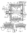
- a permanent magnet, hollow cylinder electromagnetic transducer 35 When used for vehicle propulsion, a permanent magnet, hollow cylinder electromagnetic transducer 35 may be utilized as an efficient wheel mounted traction motor, and may, as indicated in FIGURE 3, be mounted directly at each wheel 37, adjacent to axle 39, with drive being preferably achieved gear reduction mechanism 41.
- electromagnetic transducer 35 includes an outer cylindrical housing 43, which housing has front and rear end plates 45 and 46 positioned at the opposite ends of the cylindrical housing by means of snap rings 48 and 49.
- a shaft 51 has a central portion 52 extending through the cylindrical housing with the shaft being mounted in central hubs 54 and 55 of end plates 45 and 46, respectively, by means of bearings 57 and 58 so that the central portion of the shaft is coaxially positioned with respect to the cylindrical housing, the reduced diameter rear portion 60 of the shaft is mounted in bearing 58, and the front portion 62 of the shaft extends forwardly of front end plate 45, with seal 64 being positioned in hub 54 adjacent to bearing 57.
- blower 65 is positioned adjacent to back, or rear, end plate 46, which plate includes offset air intake aperture 66 and a plurality of exhaust apertures 67 spaced about and near the periphery of the end plate.
- the transducer thus operates in a gas (air) medium (as opposed to a fluid medium which could include oil or the like, for example, as do some known transducers).
- an arcuate aperture 68 is positioned to allow armature conductor connections through end plate 46.
- rotor 70 has a double shell configuration provided by inner and outer spaced cylindrical portions 72 and 73 which extend normally from mounting disk 75 so that cylindrical portions 72 and 73 are coaxial with, and inside, cylindrical housing 43 and define an annular gap 72A therebetween.
- Mounting disk 75 has an annular mounting portion 77 which is received on splined portion 78 of shaft 51 inwardly of bearing 57.
- Inner cylindrical portion 72 of rotor 70 has magnetic elements 80 mounted thereon, which magnetic elements are shown to be permanent magnets (but electromagnets could be utilized, if desired).
- Cylindrical portions 72 and 73 are formed of highly magnetically permeable with low hysteresis loss magnetic material (such as iron or steel, for example), and mounting disk 75 is formed of non-magnetic material (such as plastic or aluminium, for example), while magnetic elements 80 are high strength permanent magnets, which magnets are preferably formed of neodymium boron ferrite (NdFeB), but may also be formed of barium ferrite ceramic (BaFe Ceramic), samarium cobalt (SmCo), or the like.
- NdFeB neodymium boron ferrite
- BaFe Ceramic barium ferrite ceramic
- SmCo samarium cobalt
- Armature 82 is fixed with respect to housing 43, and is mounted on rear end plate 46, as indicated in FIGURE 2, so that rotor 70 rotates relative to armature 82 (as well as to housing 43).
- Armature 82 comprises an annular member at least partially disposed within gap 72A and is thus a stationary cylindrical shell element that extends through the length of cylindrical housing 43 between the inner and outer cylindrical portions 72 and 73 of the rotor.
- armature 82 include dispersed conductors 84, as best shown in FIGURE 4, different sections 85 of which are positioned between flux carrying elements 86 as best shown in FIGURE 6.
- the conducters 84 have discrete, spaced apart active regions 84A, as shown in Fig. 4 and 5.
- active regions 84A have a substantially rectangular cross-section.
- a flux carrying means formed of a plurality of flux carrying members 86 of compressed iron powder are interposed in open space areas 86A between active regions 84A.
- Dispersed conductors 84 are preferably formed from a bundle of small diameter copper wires 87 surrounded by insulating material 88 (as best shown in FIGURE 11), with conductors 84 being wound into a linking pattern, as indicated by way of example in FIGURE 5, with the opposite ends of the wire bundles being connected to connectors 89 extending through aperture 68 in end plate 46, as indicated in FIGURE 2.
- Conductors 84 are formed into a bundle throughout the armature (as by being wound in a ring, for example), and each turn of the wire windings has a flux carrying element 86 therebetween, as shown in FIGURES 5 and 6, with a typical winding which constitutes a structurally integral annular winding structure being conceptually illustrated in FIGURE 5.
- Flux carrying elements 86 are preferably iron (at least in part), and extend between the active region or length 84A of conductors 84. Elements 86 have radially inner 86B and radially outer 86C elengated edges (see Fig. 5). Conductors 84 also have flat end turns 84B at which the winding conductors 84 are reversed in direction (see Figs. 4 and 5).
- the flux carrying elements 86 are preferably dispersed-phase flux carrying members to handle the high frequency magnetic field reversals with low opposing induced currents and low eddy current losses. Because iron is electrically conductive, it must be dispersed to avoid (or at least minimize) the creation of opposing induced currents. It has been found that a suitable flux carrying element 86 can be pressed from fine (10-100 micron) iron powder previously reactively coated with phosphate insulation and using "B" stage epoxy and wax as binders.
- a stationary armature shell incorporating windings of copper with powdered iron bars to carry the magnetic flux, and permeated with glass reenforced novolac epoxy insulation material cast as a bonding agent 180 between the windings and bars, has been successfully utilized.
- armature 82 (formed by the dispersed conductors 84 and flux carrying members 86) are closely spaced with respect to magnets 80 positioned about the inner cylindrical wall 72, and also closely spaced with respect to cylindrical wall 73, with walls 72 and 73 providing inner and outer return paths, respectively, for the magnetic flux.
- Some typical flux paths have been illustrated in FIGURE 6. As shown, these flux paths are loops each of which penetrates the armature twice passing principally through the flux carrying members 86. The flux carrying members thus allow a thick armature to maintain a high flux density which is essential to high torque.
- the electromagnetic transducer may also be configured by placing magnets 80 on outer wall 73 (rather than on inner wall 72). As indicated in FIGURE 8, the electromagnetic transducer may also be configured by placing magnets 80 on both inner and outer walls 72 and 73.
- an armature 82 can also be provided at both sides of magnets 80.
- the electromagnetic transducer could be configured by placing additional layers of armature-rotor elements radially inwardly and/or outwardly of that shown in the drawings.
- flux carrying members 86 in the above embodiment are rectangular in cross-section the flux carrying members may also be configured by utilizing a non-rectangularly shaped member such as, for example, an I-shaped member 91 (as indicated in FIGURE 10) having dispersed conductors 84 extending therebetween.
- the armature can also be configured as shown in FIGURE 12 such that flux carrying elements 93 are formed as a coating of highly permeable magnetic material (such as iron) on some or all of the dispersed conductors 94.
- flux carrying elements 93 are formed as a coating of highly permeable magnetic material (such as iron) on some or all of the dispersed conductors 94.
- conductors 94 can also have an insulation layer 95 thereon so that insulation layer 95 is between the conductor and the flux carrying element.
- an insulating layer 96 covers the flux carrying element (unless it is, of itself, electrically non-conductive).
- the flux carrying bars (shown in FIGURES 4 through 10) need not be utilized.
- the dispersed conductors 94 with the flux carrying elements coated thereon can be utilized as the only elements of the armature (as indicated in FIGURE 14) or can be alternated with dispersed conductor sections 85, i.e., dispersed conductors having no flux carrying element coating thereon (as indicated in FIGURE 15).
- Powdered iron utilized as flux carrying elements 86 provide three-dimensional phase dispersion, while flux carrying elements 93 coated on the dispersed conductors (as indicated in FIGURES 12 and 13) provide two-dimensional phase dispersion (iron lamination bars, on the other hand, when used as flux carrying elements provide only one-dimensional phase dispersion).
- the electromagnetic transducer of this invention thus includes a magnetic flux producing assembly (having at least one pair of poles which can be embodied by using permanent magnets or electromagnets), and an armature assembly (which intercepts the magnetic flux produced by the magnetic flux producing assembly and has an alternating structure of conductive windings and flux carrying elements, which flux carrying elements can be referred to as armature iron).
- a winding can be used as the principal component of the armature with the winding consisting of bundles of separate conductors (which are referred to herein as dispersed conductors), with the use of dispersed conductors of fine wire permitting high speed rotation of the rotor when used in conjunction with dispersed-phase flux carrying elements.
- a means to displace (i.e., rotate) the magnetic field relative to the armature at high speed must, of course, also be provided so that electric power can be converted into mechanical power in a manner similar to that used by known motors. As indicated in FIGURE 2, this can be accomplished by connecting leads 97 between connectors 89 of armature 82 and current generator and controller unit 98 so that unit 98 which provides current to conductors 84 to cause rotation of rotor 70, with rotation of rotor 70 causing rotation of shaft 51 to drive a load 99.
- actuator 99 When used as an alternator or generator, actuator 99 causes rotation of shaft 51 which rotates rotor 70 to induce a voltage on conductors 84 and thereby generates electrical current flow from conductors 84 to a load 98.
- the current generator and controller unit includes necessary electric commutation devices, including those devices wherein commutation is performed electronically (as in a brushless DC motor, for example), as well as those devices which employ rectifiers instead of commutation (as is often used in power generating applications).
- FIGURE 16 illustrates an embodiment of the electromagnetic transducer of this invention in which armature 82 is connected with shaft 51 by mounting disk 101, and inner and outer cylindrical walls 72 and 73 are fixed to housing 43.
- the armature thus becomes the rotor with electric power being communicated with the armature by means of brushes/slips rings 102 (with brushes being utilized in the case of a DC machine, and slip rings being utilized in the case of an AC machine).
- the embodiment shown in FIGURE 16 is preferred for some applications, particularly in the case of a DC commutated machine.
- the transducer of this invention has a significant advantage over a conventional motor by utilization of a minimum amount of iron which undergoes flux reversal. That is, only the iron in the flux carrying elements in the armature is subject to the reversing flux as each pole is passed, and thus low hysteresis losses are experienced. In addition, the effects of flux leakage are reduced so that all of the armature windings experience the total flux change and thus are equally useful at producing torque.
- the device of this invention also has significant heat transfer advantages. For this reason, the superior high power to weight ratio is further enhanced.
- a thin armature is made possible by the armature being made up entirely of insulated conductors except for the necessary volume of the flux carrying members. It is therefore possible to provide cooling to both the inner and outer surfaces of the armature.
- heat buildup in an armature depends on the square of its thickness. For example, compare an armature 0,63 cm (0.25 inches) thick (as is possible in this invention) to a solid rotor, 18,7 cm (five inches) in diameter (as is common in known devices). The heat buildup in such known devices is some 400 times as great as that of the transducer of this invention with such an armature. Clearly, the electromagnetic transducer of this invention can dissipate more heat than any known conventional transducer of similar power rating.
- the electromagnetic transducer of this invention can be produced in several topological variations of the basic design.
- the motor can be made to produce a linear motion.
- Other variations include pancake and conical configurations.
- FIGURE 17 illustrates a linear reciprocating implementation of the electromagnetic transducer of this invention wherein the magnetic flux producing section moves linearly with respect to the armature in a cylindrical configuration.
- armature 105 has dispersed conductors 106 and flux carrying elements 107 wound radially about shaft 51 (rather than extending parallel thereto as in the embodiment shown in FIGURE 1), and rotor 109 has magnets 110 thereon that extend circumferentially around inner cylindrical wall 72 (rather than extending parallel to shaft 51 as in the embodiment shown in
- FIGURE 1 1).
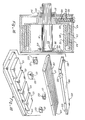
- FIGURE 18 illustrates another linear reciprocating implementation of the electromagnetic transducer of this invention in which the structure is flat.
- magnets 113 are mounted on flat lower return plate 114.
- Armature 115 is provided with dispersed conductors 116 and flux carrying elements 117 in the same manner as described hereinabove with respect to the other embodiments illustrated except that the armature is essentially flat rather than cylindrical.
- An upper return plate 118 is also provided, and armature 115 is movable linearly with respect to, and between, lower and upper plates 114 and 118 by means of rollers 120 mounted on the edges of upper plate 118 and rollers 121 mounted in roller mounting boxes 122 (carried by lower plate 114).
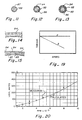
- the electromagnetic force was measured in an actual test in a linear configuration similar to that illustrated in FIGURE 18, built to test computer simulation of a rotary configuration.
- a current of 125 amps produced a force of 222,4N (50 lb.).
- the measured magnetic field (using Type 8 ceramic magnets) was 3500 gauss.
- the active conductor length spanned three of the four poles and consisted of twenty bars of copper, each 0,38 x 0,79 cm (0.150 x 0.3125 inches) in cross section.
- the force was calculated to be 200,2 N (45 Ib).
- the measured force of 222,4 N (50 Ib) compares well with the calculated force of 200,2 N (45 Ib) considering the accuracy of the test (for example, the magnetic field is not absolutely uniform everywhere, and fringing field effects were not considered).
- the electromagnetic transducer of this invention is thus able to provide an output power to weight ratio that is greater than one horsepower to one pound in a cooling gas medium (using air as the cooling medium), and is believed to be greater than five horsepower to one pound in art least some cooling mediums (with a five to one ratio being calculated for the prototype motor as set forth herein). It should be further appreciated from the foregoing that this invention provides an improved electromagnetic transducer that is lightweight, compact, efficient and yet capable of delivering high power.
Landscapes
- Engineering & Computer Science (AREA)
- Power Engineering (AREA)
- Physics & Mathematics (AREA)
- Chemical & Material Sciences (AREA)
- Combustion & Propulsion (AREA)
- Electromagnetism (AREA)
- Windings For Motors And Generators (AREA)
- Surgical Instruments (AREA)
- Superconductors And Manufacturing Methods Therefor (AREA)
- Reciprocating, Oscillating Or Vibrating Motors (AREA)
- Permanent Magnet Type Synchronous Machine (AREA)
- Connection Of Motors, Electrical Generators, Mechanical Devices, And The Like (AREA)
- Iron Core Of Rotating Electric Machines (AREA)
- Developing Agents For Electrophotography (AREA)
- Vehicle Body Suspensions (AREA)
- Dynamo-Electric Clutches, Dynamo-Electric Brakes (AREA)
- Compounds Of Iron (AREA)
- Glass Compositions (AREA)
- Optical Fibers, Optical Fiber Cores, And Optical Fiber Bundles (AREA)
- Permanent Field Magnets Of Synchronous Machinery (AREA)
- Electromagnets (AREA)
- Motor Or Generator Cooling System (AREA)
- Magnetic Bearings And Hydrostatic Bearings (AREA)
- Control Of High-Frequency Heating Circuits (AREA)
- Control Of Electric Motors In General (AREA)
- Organic Low-Molecular-Weight Compounds And Preparation Thereof (AREA)
- Measuring Pulse, Heart Rate, Blood Pressure Or Blood Flow (AREA)
- Ultra Sonic Daignosis Equipment (AREA)
- Transducers For Ultrasonic Waves (AREA)
Claims (31)
Priority Applications (1)
| Application Number | Priority Date | Filing Date | Title |
|---|---|---|---|
| AT86117875T ATE71242T1 (de) | 1985-12-23 | 1986-12-22 | Leichtgewichtiger elektromagnetischer hochleistungsumwandler. |
Applications Claiming Priority (2)
| Application Number | Priority Date | Filing Date | Title |
|---|---|---|---|
| US81230685A | 1985-12-23 | 1985-12-23 | |
| US812306 | 1985-12-23 |
Publications (4)
| Publication Number | Publication Date |
|---|---|
| EP0230639A2 EP0230639A2 (fr) | 1987-08-05 |
| EP0230639A3 EP0230639A3 (en) | 1987-08-19 |
| EP0230639B1 true EP0230639B1 (fr) | 1992-01-02 |
| EP0230639B2 EP0230639B2 (fr) | 1996-06-05 |
Family
ID=25209175
Family Applications (1)
| Application Number | Title | Priority Date | Filing Date |
|---|---|---|---|
| EP86117875A Expired - Lifetime EP0230639B2 (fr) | 1985-12-23 | 1986-12-22 | Transducteur électromagnétique allégé de forte puissance |
Country Status (26)
| Country | Link |
|---|---|
| US (2) | US5004944A (fr) |
| EP (1) | EP0230639B2 (fr) |
| JP (1) | JP2831348B2 (fr) |
| KR (1) | KR950010879B1 (fr) |
| CN (1) | CN1044541C (fr) |
| AT (1) | ATE71242T1 (fr) |
| AU (1) | AU609707B2 (fr) |
| BR (1) | BR8606392A (fr) |
| CA (1) | CA1312646C (fr) |
| DD (1) | DD252933A5 (fr) |
| DE (1) | DE3683278D1 (fr) |
| DK (1) | DK173855B1 (fr) |
| ES (1) | ES2029448T5 (fr) |
| FI (1) | FI102864B (fr) |
| GR (2) | GR3003506T3 (fr) |
| HU (1) | HUT43442A (fr) |
| IE (1) | IE71653B1 (fr) |
| IL (1) | IL81087A (fr) |
| IN (1) | IN167623B (fr) |
| MX (1) | MX161230A (fr) |
| NO (1) | NO865229L (fr) |
| NZ (1) | NZ218718A (fr) |
| PL (1) | PL263215A1 (fr) |
| RU (1) | RU2083051C1 (fr) |
| YU (1) | YU220486A (fr) |
| ZA (1) | ZA869543B (fr) |
Cited By (3)
| Publication number | Priority date | Publication date | Assignee | Title |
|---|---|---|---|---|
| US5319844A (en) | 1985-12-23 | 1994-06-14 | Unique Mobility, Inc. | Method of making an electromagnetic transducer |
| US11770048B2 (en) | 2013-10-18 | 2023-09-26 | Black & Decker, Inc. | Handheld power tool with a brushless electric motor |
| EP4333266A1 (fr) | 2022-09-02 | 2024-03-06 | maxon international ag | Moteur électrique à commutation électronique |
Families Citing this family (145)
| Publication number | Priority date | Publication date | Assignee | Title |
|---|---|---|---|---|
| MX161230A (es) * | 1985-12-23 | 1990-08-24 | Unique Mobility Inc | Mejoras en transductor electromagnetico de peso ligero |
| US5548657A (en) * | 1988-05-09 | 1996-08-20 | Kef Audio (Uk) Limited | Compound loudspeaker drive unit |
| GB8810943D0 (en) * | 1988-05-09 | 1988-06-15 | Kef Electronics Ltd | Loudspeaker |
| US4900965A (en) * | 1988-09-28 | 1990-02-13 | Fisher Technology, Inc. | Lightweight high power electromotive device |
| US5257639A (en) * | 1988-12-23 | 1993-11-02 | Dresser Industries, Inc. | Electropneumatic positioner |
| US4926896A (en) * | 1988-12-23 | 1990-05-22 | Dresser Industries, Inc. | Sensitive electrical to mechanical transducer |
| US5206556A (en) * | 1989-08-29 | 1993-04-27 | Mabuchi Motor Co., Ltd. | Field magnet for miniature motors |
| JPH069578Y2 (ja) * | 1989-08-29 | 1994-03-09 | マブチモーター株式会社 | 小型モータ用界磁マグネット |
| DE3933790C2 (de) * | 1989-10-10 | 1994-03-17 | Werner Anwander | Elektrische Maschine mit einem Rotor und einem Stator |
| NZ232333A (en) * | 1990-02-01 | 1993-12-23 | Cadac Holdings Ltd | Motor stator wound with high permeability material. |
| EP0522015B1 (fr) * | 1990-03-30 | 2000-08-30 | Unique Mobility, Inc. | Procede de fabrication d'un transducteur electromagnetique |
| GB9112059D0 (en) * | 1991-06-05 | 1991-07-24 | Jestar Ltd | Electrical machines |
| US5212419A (en) * | 1992-01-10 | 1993-05-18 | Fisher Electric Motor Technology, Inc. | Lightweight high power electromotive device |
| US5455473A (en) * | 1992-05-11 | 1995-10-03 | Electric Power Research Institute, Inc. | Field weakening for a doubly salient motor with stator permanent magnets |
| JP3152405B2 (ja) * | 1992-06-10 | 2001-04-03 | オークマ株式会社 | 電動機 |
| CA2098151A1 (fr) * | 1992-06-11 | 1993-12-12 | Russell S. Gurstein | Cireuse de paquets refroidie a l'air |
| US5382859A (en) * | 1992-09-01 | 1995-01-17 | Unique Mobility | Stator and method of constructing same for high power density electric motors and generators |
| WO1994009548A1 (fr) * | 1992-10-19 | 1994-04-28 | Lmc Operating Corp. | Vehicule electrique a chenilles |
| US5363937A (en) * | 1992-10-19 | 1994-11-15 | Lmc Operating Corp. | Battery operated tracked vehicle |
| US5753989A (en) * | 1993-06-14 | 1998-05-19 | Ecoair Corp. | Hybrid alternator |
| US5693995A (en) | 1993-06-14 | 1997-12-02 | Ecoair Corp. | Hybrid alternator |
| US5404063A (en) * | 1993-07-01 | 1995-04-04 | Mills; Herbert W. | Electromagnetic center core dynamo |
| US5595121A (en) * | 1994-04-15 | 1997-01-21 | The Walt Disney Company | Amusement ride and self-propelled vehicle therefor |
| US5705917A (en) * | 1994-09-14 | 1998-01-06 | Coleman Powermate, Inc. | Light weight machine with rotor employing permanent magnets and consequence poles |
| US6118186A (en) * | 1994-09-14 | 2000-09-12 | Coleman Powermate, Inc. | Throttle control for small engines and other applications |
| US5929611A (en) * | 1994-09-14 | 1999-07-27 | Coleman Powermate, Inc. | Light weight rotor and stator with multiple coil windings in thermal contact |
| WO1996012337A1 (fr) * | 1994-10-14 | 1996-04-25 | Magnetic Bearing Technologies, Inc. | Generatrice sans balais |
| US5783894A (en) * | 1995-10-31 | 1998-07-21 | Wither; Thomas A. | Method and apparatus for generating electrical energy |
| US5955806A (en) * | 1995-12-01 | 1999-09-21 | Raytheon Company | Torque motor with combined shield ring and rotor ring |
| US6037690A (en) * | 1996-01-08 | 2000-03-14 | Hill; Wolfgang | Energy conversion system mounted in a wheel hub |
| EP0798844A1 (fr) * | 1996-03-28 | 1997-10-01 | Tai-Her Yang | Dispositif motorisé combiné ayant une structure électromécanique à trois couches avec structures communes |
| KR100269139B1 (ko) * | 1997-12-16 | 2000-10-16 | 윤종용 | 자기보상형 밸런서 |
| DE69912666T2 (de) * | 1998-03-25 | 2004-05-13 | Nissan Motor Co., Ltd., Yokohama | Motor/Generator |
| DE69912504T2 (de) * | 1998-03-25 | 2004-05-06 | Nissan Motor Co., Ltd., Yokohama | Motor/Generator |
| GB2338840B (en) * | 1998-04-16 | 2003-07-09 | Snr John Patrick Ettridge | An Electrical Machine |
| DE19838378A1 (de) * | 1998-08-24 | 2000-03-02 | Magnet Motor Gmbh | Elektrische Maschine mit Dauermagneten |
| WO2000038297A1 (fr) * | 1998-12-22 | 2000-06-29 | Rush Holdings, Inc. | Machine a armature et a entrefer en forme de coupelle |
| US6111329A (en) | 1999-03-29 | 2000-08-29 | Graham; Gregory S. | Armature for an electromotive device |
| DE29909817U1 (de) | 1999-06-05 | 1999-11-18 | Remus, Hans-Jürgen, Dr., St-Aubin | Bürstenloser Wechselstrom-Außenläufer-Generator |
| DE19925764A1 (de) * | 1999-06-05 | 2000-12-07 | Remus Hans Juergen | Bürstenloser Wechselstrom-Außenläufer-Generator |
| DE29909818U1 (de) | 1999-06-05 | 1999-09-02 | Remus, Hans-Jürgen, Dr., St-Aubin | Bürstenloser Außenläufer-Motor und bürstenloser Außenläufer-Generator |
| DE19925765A1 (de) * | 1999-06-05 | 2000-12-07 | Remus Hans Juergen | Bürstenloser Außenläufer-Motor und bürstenloser Außenläufer-Generator |
| GB9919065D0 (en) * | 1999-08-12 | 1999-10-13 | Fast Technology Gmbh | Transducer Element |
| US6703741B1 (en) | 1999-09-20 | 2004-03-09 | Ecoair Corp. | Permanent magnet rotor portion for electric machines |
| DE10084941T1 (de) * | 1999-09-20 | 2002-08-14 | Ecoair Corp | Permanentmagnetischer Rotorabschnitt für elektrische Maschinen |
| US6633106B1 (en) | 1999-09-30 | 2003-10-14 | Dwight W. Swett | Axial gap motor-generator for high speed operation |
| KR100347014B1 (ko) * | 1999-11-10 | 2002-08-03 | 한국과학기술원 | 코어리스 교류 유도전동기 |
| DE19957008A1 (de) * | 1999-11-26 | 2001-06-28 | Sonderprojekte Anlagen & Hande | Elektrische Gleichstrommaschine mit Permanentpolen und Anker |
| FR2802358B1 (fr) * | 1999-12-08 | 2002-01-18 | Centre Nat Rech Scient | Moteur/generatrice a reluctance excitee et a bobinage dans l'entrefer |
| US6891302B1 (en) | 2000-09-23 | 2005-05-10 | Christopher W. Gabrys | Light-weight high-power electrical machine |
| US8198746B2 (en) * | 2000-11-15 | 2012-06-12 | Borealis Technical Limited | Chimney turbine |
| US6873085B2 (en) * | 2001-05-16 | 2005-03-29 | G & G Technology, Inc. | Brushless motor |
| US6741007B2 (en) | 2001-07-27 | 2004-05-25 | Beacon Power Corporation | Permanent magnet motor assembly having a device and method of reducing parasitic losses |
| JP2003070219A (ja) * | 2001-08-24 | 2003-03-07 | Alps Electric Co Ltd | モータ及びディスク装置 |
| ITBZ20010043A1 (it) * | 2001-09-13 | 2003-03-13 | High Technology Invest Bv | Generatore elettrico azionato da energia eolica. |
| US6700251B2 (en) * | 2001-11-06 | 2004-03-02 | Citizen Electronics Co., Ltd. | Vibrating device for axially vibrating a movable member |
| US6727632B2 (en) * | 2001-11-27 | 2004-04-27 | Denso Corporation | Flat rotary electric machine |
| JP4089808B2 (ja) * | 2001-12-25 | 2008-05-28 | ケミテック株式会社 | 上消し可能なマイクロカプセル磁気泳動表示シート |
| RU2225065C2 (ru) * | 2002-05-06 | 2004-02-27 | Акционерное общество открытого типа "Электросила" | Электромашинный преобразователь |
| US20040021437A1 (en) * | 2002-07-31 | 2004-02-05 | Maslov Boris A. | Adaptive electric motors and generators providing improved performance and efficiency |
| US20050046375A1 (en) * | 2002-07-31 | 2005-03-03 | Maslov Boris A. | Software-based adaptive control system for electric motors and generators |
| US20050127856A1 (en) * | 2002-07-31 | 2005-06-16 | Wavecrest Laboratories | Low-voltage electric motors |
| US20040263099A1 (en) * | 2002-07-31 | 2004-12-30 | Maslov Boris A | Electric propulsion system |
| US20050045392A1 (en) * | 2002-07-31 | 2005-03-03 | Maslov Boris A. | In-wheel electric motors |
| US20040071003A1 (en) * | 2002-09-04 | 2004-04-15 | G & G Technology, Inc. | Split phase polyphase inverter |
| US20040174082A1 (en) * | 2003-03-04 | 2004-09-09 | Graham Gregory S. | Multiple concentric coil motor |
| US7294947B2 (en) * | 2004-03-01 | 2007-11-13 | Flux Drive, Inc. | Apparatus for transferring torque magnetically |
| WO2005089327A2 (fr) * | 2004-03-14 | 2005-09-29 | Revolution Electric Motor Company, Inc. | Moteur-generateur a haut rendement et a faible cout |
| US7154191B2 (en) * | 2004-06-30 | 2006-12-26 | General Electric Company | Electrical machine with double-sided rotor |
| US7154192B2 (en) * | 2004-09-27 | 2006-12-26 | General Electric Company | Electrical machine with double-sided lamination stack |
| US7154193B2 (en) * | 2004-09-27 | 2006-12-26 | General Electric Company | Electrical machine with double-sided stator |
| CA2573089C (fr) | 2004-07-19 | 2011-11-22 | Rotatek Finland Oy | Machine electrique rotative basee sur le principe d'une machine lineaire |
| ITBZ20040047A1 (it) | 2004-09-20 | 2004-12-20 | High Technology Invest Bv | Generatore/motore elettrico, in particolare per l'impiego in impianti eolici, impianti a fune o idraulici. |
| US7839048B2 (en) * | 2004-09-27 | 2010-11-23 | General Electric Company | Electrical machine with double-sided stator |
| US7548008B2 (en) * | 2004-09-27 | 2009-06-16 | General Electric Company | Electrical machine with double-sided lamination stack |
| US7411325B1 (en) * | 2004-10-20 | 2008-08-12 | Revolution Electric Motor Company, Inc. | High efficiency combination motor and drive |
| KR100629335B1 (ko) * | 2004-10-29 | 2006-09-29 | 엘지전자 주식회사 | 전동기와 그 계자 제작 방법과 그를 갖는 세탁기 |
| US7692357B2 (en) * | 2004-12-16 | 2010-04-06 | General Electric Company | Electrical machines and assemblies including a yokeless stator with modular lamination stacks |
| US7227276B2 (en) * | 2005-08-08 | 2007-06-05 | Caiozza Joseph C | Wind driven electric generator apparatus |
| US7402934B1 (en) * | 2005-08-18 | 2008-07-22 | Revolution Motor Company, Inc. | High performance air core motor-generator winding |
| RU2309510C2 (ru) * | 2005-08-29 | 2007-10-27 | Открытое акционерное общество "Научно-производственный центр "Полюс" (ОАО "НПЦ "Полюс") | Ротор электрической машины с постоянными магнитами |
| ITBZ20050062A1 (it) * | 2005-11-29 | 2007-05-30 | High Technology Invest Bv | Rotore a magneti permanenti per generatori e motori elettrici |
| WO2007034305A1 (fr) * | 2005-09-21 | 2007-03-29 | High Techonology Investments, B.V. | Systeme d'etancheite de roulement a joint a vis et a garniture a labyrinthes combines |
| ITBZ20050063A1 (it) * | 2005-11-29 | 2007-05-30 | High Technology Invest Bv | Pacco di lamierini per generatori e motori elettrici e procedimento per la sua attuazione |
| KR20080055848A (ko) * | 2005-09-28 | 2008-06-19 | 아이티티 매뉴팩츄어링 엔터프라이즈, 인코포레이티드 | 영구자석 모터에 사용하기 위한 회전자에 자석 부재를장착하는 방법 |
| RU2302692C9 (ru) * | 2005-10-05 | 2007-11-10 | Закрытое Акционерное Общество Научно-Производственное Предприятие "Инкар-М" | Электромеханический преобразователь |
| US7750515B1 (en) * | 2005-10-25 | 2010-07-06 | Gabrys Christopher W | Industrial air core motor-generator |
| RU2313884C2 (ru) * | 2005-11-08 | 2007-12-27 | Алексей Владимирович Булычев | Электрическая машина (варианты) |
| RU2313885C2 (ru) * | 2005-12-21 | 2007-12-27 | Алексей Владимирович Булычев | Электрическая машина (варианты) |
| RU2311716C2 (ru) * | 2006-01-13 | 2007-11-27 | Алексей Владимирович Булычев | Электрическая машина (варианты) |
| US7902700B1 (en) * | 2006-04-03 | 2011-03-08 | Gabrys Christopher W | Low harmonic loss brushless motor |
| CN101072489B (zh) * | 2006-05-10 | 2010-09-08 | 建准电机工业股份有限公司 | 复合散热模组 |
| CN101627208A (zh) * | 2006-12-22 | 2010-01-13 | 高技术投资公司 | 多发电机式风轮机 |
| US7592736B2 (en) * | 2007-01-03 | 2009-09-22 | Terry Scott | Permanent magnet electric generator with rotor circumferentially encircling stator |
| US20090010784A1 (en) * | 2007-07-06 | 2009-01-08 | Mbs Engineering, Llc | Powdered metals and structural metals having improved resistance to heat and corrosive fluids and b-stage powders for making such powdered metals |
| US7791233B1 (en) | 2007-10-24 | 2010-09-07 | Attard Michael T | High torque electric motor/flywheel |
| BRPI0802090A2 (pt) * | 2008-05-23 | 2010-01-19 | Associacao Keppe & Pacheco | motor elÉtromagnÉtico e equipamento gerador de torque de trabalho |
| KR100963745B1 (ko) | 2008-06-12 | 2010-06-14 | 한국전력공사 | 회전 코어형 전동 및 발전 장치 |
| ITMI20081122A1 (it) | 2008-06-19 | 2009-12-20 | Rolic Invest Sarl | Generatore eolico provvisto di un impianto di raffreddamento |
| WO2009156862A2 (fr) * | 2008-06-27 | 2009-12-30 | Pii (Canada) Limited | Contrôle non destructif intégré multi-capteurs |
| IT1390758B1 (it) | 2008-07-23 | 2011-09-23 | Rolic Invest Sarl | Generatore eolico |
| IT1391939B1 (it) * | 2008-11-12 | 2012-02-02 | Rolic Invest Sarl | Generatore eolico |
| IT1391770B1 (it) | 2008-11-13 | 2012-01-27 | Rolic Invest Sarl | Generatore eolico per la generazione di energia elettrica |
| IT1392804B1 (it) * | 2009-01-30 | 2012-03-23 | Rolic Invest Sarl | Imballo e metodo di imballo per pale di generatori eolici |
| IT1393937B1 (it) * | 2009-04-09 | 2012-05-17 | Rolic Invest Sarl | Aerogeneratore |
| IT1393707B1 (it) | 2009-04-29 | 2012-05-08 | Rolic Invest Sarl | Impianto eolico per la generazione di energia elettrica |
| US20100304920A1 (en) * | 2009-05-28 | 2010-12-02 | Bernard Joseph Simon | Hybrid Assembly , A Hybrid Power-Train , And A Method For Operating A Selectively Movable Assembly |
| IT1394723B1 (it) | 2009-06-10 | 2012-07-13 | Rolic Invest Sarl | Impianto eolico per la generazione di energia elettrica e relativo metodo di controllo |
| IT1395148B1 (it) * | 2009-08-07 | 2012-09-05 | Rolic Invest Sarl | Metodo e apparecchiatura di attivazione di una macchina elettrica e macchina elettrica |
| IT1397081B1 (it) | 2009-11-23 | 2012-12-28 | Rolic Invest Sarl | Impianto eolico per la generazione di energia elettrica |
| IT1398060B1 (it) | 2010-02-04 | 2013-02-07 | Wilic Sarl | Impianto e metodo di raffreddamento di un generatore elettrico di un aerogeneratore, e aerogeneratore comprendente tale impianto di raffreddamento |
| KR101219745B1 (ko) * | 2010-03-22 | 2013-01-08 | 한국화학연구원 | 조류제거장치 |
| IT1399201B1 (it) | 2010-03-30 | 2013-04-11 | Wilic Sarl | Aerogeneratore e metodo di rimozione di un cuscinetto da un aerogeneratore |
| IT1399511B1 (it) | 2010-04-22 | 2013-04-19 | Wilic Sarl | Generatore elettrico per un aerogeneratore e aerogeneratore equipaggiato con tale generatore elettrico |
| RU2424611C1 (ru) * | 2010-06-16 | 2011-07-20 | Георгий Анатольевич Пархоменко | Бесконтактный электродвигатель |
| ITMI20110377A1 (it) | 2011-03-10 | 2012-09-11 | Wilic Sarl | Macchina elettrica rotante per aerogeneratore |
| ITMI20110378A1 (it) | 2011-03-10 | 2012-09-11 | Wilic Sarl | Macchina elettrica rotante per aerogeneratore |
| ITMI20110375A1 (it) | 2011-03-10 | 2012-09-11 | Wilic Sarl | Turbina eolica |
| AR083135A1 (es) * | 2011-10-05 | 2013-02-06 | Ind Metalurgicas Pescarmona S A I C Y F | Generador eolico sincronico |
| US10263480B2 (en) | 2012-03-20 | 2019-04-16 | Linear Labs, LLC | Brushless electric motor/generator |
| US9729016B1 (en) | 2012-03-20 | 2017-08-08 | Linear Labs, Inc. | Multi-tunnel electric motor/generator |
| US10284029B2 (en) * | 2012-03-20 | 2019-05-07 | Linear Labs, LLC | Brushed electric motor/generator |
| CA2881979C (fr) * | 2012-03-20 | 2021-04-20 | Linear Labs, Inc. | Un moteur cc/generateur ayant des densites ameliorees de flux d'aimant permanent |
| TWI538358B (zh) * | 2012-04-25 | 2016-06-11 | Yi-Chen Liu | Electromagnetic actuated converters that can be adjusted for performance matching |
| JP5742805B2 (ja) * | 2012-09-13 | 2015-07-01 | トヨタ自動車株式会社 | 回転電機の固定子 |
| CN106716793B (zh) | 2014-09-04 | 2019-06-25 | M-链接株式会社 | 具备包含圆筒线圈的定子的无铁心旋转电力机构及其冷却方法 |
| US10447103B2 (en) | 2015-06-28 | 2019-10-15 | Linear Labs, LLC | Multi-tunnel electric motor/generator |
| US10476362B2 (en) | 2015-06-28 | 2019-11-12 | Linear Labs, LLC | Multi-tunnel electric motor/generator segment |
| EP3118971B1 (fr) * | 2015-07-14 | 2018-05-02 | Kabushiki Kaisha Toshiba | Machine électrique rotative et véhicule |
| US11139707B2 (en) | 2015-08-11 | 2021-10-05 | Genesis Robotics And Motion Technologies Canada, Ulc | Axial gap electric machine with permanent magnets arranged between posts |
| WO2017024409A1 (fr) | 2015-08-11 | 2017-02-16 | Genesis Robotics Llp | Machine électrique |
| DE202015006632U1 (de) * | 2015-09-17 | 2016-09-26 | Rainer Schmieg | Koaxialgenerator für eine Turbine |
| AU2016342255B2 (en) | 2015-10-20 | 2020-09-24 | Linear Labs, Inc. | A circumferential flux electric machine with field weakening mechanisms and methods of use |
| JP6005886B1 (ja) * | 2016-03-03 | 2016-10-12 | 株式会社エムリンク | 円筒コイルを備えた固定子を含む無鉄心回転電気機械およびその冷却方法 |
| US11043885B2 (en) | 2016-07-15 | 2021-06-22 | Genesis Robotics And Motion Technologies Canada, Ulc | Rotary actuator |
| CN107979254A (zh) * | 2016-07-15 | 2018-05-01 | 苏州宝时得电动工具有限公司 | 一种电机以及电动工具 |
| WO2018045360A2 (fr) | 2016-09-05 | 2018-03-08 | Linear Labs, Inc. | Moteur/générateur électrique multi-tunnel amélioré |
| US10214089B2 (en) * | 2016-10-18 | 2019-02-26 | Richard Chi-Hsueh | Energy efficient vehicle |
| CN108361347A (zh) * | 2017-01-13 | 2018-08-03 | 熵零技术逻辑工程院集团股份有限公司 | 一种变矩器 |
| FR3068539A1 (fr) * | 2017-06-30 | 2019-01-04 | Commissariat A L'energie Atomique Et Aux Energies Alternatives | Convertisseur d'energie electromagnetique |
| JP7001016B2 (ja) * | 2017-12-28 | 2022-01-19 | 株式会社デンソー | 車輪駆動装置 |
| JP7225901B2 (ja) * | 2019-02-25 | 2023-02-21 | 株式会社デンソー | 回転電機 |
| US11277062B2 (en) | 2019-08-19 | 2022-03-15 | Linear Labs, Inc. | System and method for an electric motor/generator with a multi-layer stator/rotor assembly |
| CN110548607A (zh) * | 2019-08-30 | 2019-12-10 | 贾力 | 节能环保有机垃圾处理机 |
| CN212695878U (zh) * | 2020-05-19 | 2021-03-12 | 陆继荣 | 稀土永磁轴向双磁路无铁芯发电机 |
Citations (1)
| Publication number | Priority date | Publication date | Assignee | Title |
|---|---|---|---|---|
| US3602749A (en) | 1970-02-20 | 1971-08-31 | Ernie B Esters | Dynamoelectric machine |
Family Cites Families (171)
| Publication number | Priority date | Publication date | Assignee | Title |
|---|---|---|---|---|
| US295368A (en) * | 1884-03-18 | dennis | ||
| US464026A (en) * | 1891-12-01 | Transformer and armature-core | ||
| US3125402A (en) * | 1964-03-17 | Xcx ch | ||
| US497001A (en) * | 1893-05-09 | Rookes evelyn | ||
| US1227185A (en) * | 1915-09-01 | 1917-05-22 | Alfons H Neuland | Induction device. |
| US1456955A (en) * | 1921-02-26 | 1923-05-29 | Westinghouse Electric & Mfg Co | Means for obtaining high momentary current |
| DE843866C (de) * | 1948-10-02 | 1952-07-14 | Siemens Ag | Synchronkleinmotor fuer Einphasenwechselstrom |
| US2792511A (en) * | 1954-03-17 | 1957-05-14 | Westinghouse Electric Corp | Oriented-punching cores for dynamoelectric machines |
| US3082337A (en) * | 1955-09-26 | 1963-03-19 | Parsons C A & Co Ltd | Dynamo-electric machines |
| US3069557A (en) * | 1957-06-06 | 1962-12-18 | Texas Instruments Inc | Function generator utilizing non-conducting side of a binary chain |
| US3014139A (en) * | 1959-10-27 | 1961-12-19 | Gen Electric | Direct-cooled cable winding for electro magnetic device |
| FR1272083A (fr) * | 1960-08-03 | 1961-09-22 | Electronique & Automatisme Sa | Perfectionnements aux machines électriques tournantes |
| US3134037A (en) * | 1960-10-21 | 1964-05-19 | Napier & Son Ltd | Motor with hydrodynamic supported rotor |
| US3102964A (en) * | 1961-04-13 | 1963-09-03 | Black & Decker Mfg Co | High-efficiency permanent magnet motor |
| US3121851A (en) * | 1961-09-06 | 1964-02-18 | Northrop Corp | Electromagnetic transducer |
| CH391863A (de) * | 1962-04-04 | 1965-05-15 | Sulzer Ag | Elektrischer Motor |
| US3128402A (en) * | 1962-05-17 | 1964-04-07 | Jr Owen D Amick | Direct current generator |
| FR1341582A (fr) * | 1962-09-11 | 1963-11-02 | Electronique & Automatisme Sa | Perfectionnements aux machines électriques tournantes |
| CH436450A (de) | 1963-02-20 | 1967-05-31 | Circuit Res Co | Elektromechanischer Energieumsetzer |
| US3322986A (en) * | 1964-04-03 | 1967-05-30 | Sperry Rand Corp | Gyroscopic rotor |
| US3297891A (en) * | 1964-06-03 | 1967-01-10 | Gen Motors Corp | Brushless direct current motor |
| US3275863A (en) * | 1965-02-01 | 1966-09-27 | Elliott M Norton | Electric machine construction |
| US3396296A (en) * | 1967-06-05 | 1968-08-06 | Ernie B. Esters | Electric motors and generators |
| CH463287A (de) * | 1967-10-18 | 1968-09-30 | Oerlikon Maschf | Antriebsanordnung mit Schwungrad |
| FR1552560A (fr) * | 1968-01-30 | 1969-01-03 | ||
| US3495114A (en) * | 1968-06-14 | 1970-02-10 | Vasily Mikhailovich Kz | Cylindrical and disc stators for electrical machines having composite windings |
| US3567980A (en) * | 1969-02-03 | 1971-03-02 | Robertshaw Controls Co | Reversible motor with axially moveable rotor |
| FR2036866A1 (fr) * | 1969-04-11 | 1970-12-31 | Novosib Elektrotekh | |
| US3566165A (en) * | 1969-05-06 | 1971-02-23 | Gen Motors Corp | Electric vehicle drive motor |
| US3729642A (en) * | 1970-02-20 | 1973-04-24 | E Esters | Plural stator dynamoelectric machine |
| US3858071A (en) * | 1970-05-28 | 1974-12-31 | Ibm | High frequency, low inductance generator |
| US3638056A (en) * | 1970-06-24 | 1972-01-25 | Paul Imris | Electrical generation apparatus |
| US3663850A (en) * | 1970-08-03 | 1972-05-16 | Phelon Co Inc | Field means for a dynamoelectric machine, magnet preassembly for use therein |
| US3659129A (en) * | 1970-09-15 | 1972-04-25 | Gen Electric | Insulated bar dynamoelectric machine and method of forming |
| US3861484A (en) * | 1971-02-01 | 1975-01-21 | Kenneth E Joslin | Hybrid vehicular power system |
| US3882950A (en) * | 1972-07-11 | 1975-05-13 | James Neil Strohlein | Vehicle power system for limited vehicle movement without use of fuel |
| US4128364A (en) * | 1972-11-23 | 1978-12-05 | Papst-Motoren Kg | Radial flow fan with motor cooling and resilient support of rotor shaft |
| US3843338A (en) * | 1972-12-08 | 1974-10-22 | Beam Prod Mfg Co | Gaseous fuel carburetor including improved metering and distribution systems |
| CA1029788A (fr) | 1973-09-11 | 1978-04-18 | Westinghouse Electric Corporation | Induits bobines pour machine dynamoelectriques et methode de fabrication |
| FR2247846B1 (fr) * | 1973-10-15 | 1980-05-09 | Labavia | |
| US3874472A (en) * | 1974-01-25 | 1975-04-01 | West Virginia High Bird Corp | Battery powered vehicle drive |
| US3845338A (en) * | 1974-02-20 | 1974-10-29 | Transicoil Inc | Direct current shell armature motor |
| FR2268381B1 (fr) * | 1974-04-17 | 1980-01-04 | Alsthom Cgee | |
| CH573678A5 (fr) * | 1974-06-25 | 1976-03-15 | Bbc Brown Boveri & Cie | |
| US3965382A (en) * | 1974-10-03 | 1976-06-22 | General Electric Company | Rotor having balance weights |
| DE2460630B2 (de) * | 1974-12-20 | 1976-09-30 | Siemens AG, 1000 Berlin und 8000 München | Dauermagneterregte gleichstrommaschine |
| US4015154A (en) * | 1974-12-23 | 1977-03-29 | Sony Corporation | Motor and method for making same |
| US4004167A (en) * | 1975-01-29 | 1977-01-18 | Magna Motors Corporation | Permanent magnet stators |
| US4025831A (en) * | 1975-02-18 | 1977-05-24 | Webb Robert L | Brushless direct current motor |
| JPS5246207U (fr) * | 1975-07-23 | 1977-04-01 | ||
| IL47843A0 (en) * | 1975-07-31 | 1975-10-15 | Miller M | Drive system for high inertia load |
| JPS5346617A (en) * | 1976-10-08 | 1978-04-26 | Pioneer Electronic Corp | Brushless motor |
| JPS5355007A (en) * | 1976-10-27 | 1978-05-19 | Matsushita Electric Ind Co Ltd | Guide ram of magnetic recorder-reproducer |
| US4114057A (en) * | 1976-12-06 | 1978-09-12 | Esters Ernie B | Dynamoelectric machine with inner and outer stators |
| US4233858A (en) * | 1976-12-27 | 1980-11-18 | The Garrett Corporation | Flywheel drive system having a split electromechanical transmission |
| US4169235A (en) * | 1977-03-10 | 1979-09-25 | Hitachi, Ltd. | Electric motor with a built-up type rotor using tapered sections |
| US4110652A (en) * | 1977-03-16 | 1978-08-29 | General Electric Company | Mounting assembly for laminated rotor rim of dynamoelectric generator rotatable about inclined shaft |
| US4149309A (en) * | 1977-07-27 | 1979-04-17 | Mitsui Mfg. Co., Ltd. | Laminated core manufacture |
| DE2833899A1 (de) * | 1977-08-03 | 1979-02-15 | Micro Technology Lab Co | Stabfoermiger als fester koerper ausgebildeter rotor |
| US4146809A (en) * | 1977-09-15 | 1979-03-27 | Westinghouse Electric Corp. | Sleeve for a rotor of a dynamoelectric machine |
| DE2833168A1 (de) * | 1977-10-10 | 1980-02-07 | Siegfried Dipl Ing Haussmann | Einfache anordnung zur verminderung der ankerrueckwirkung in elektrischen maschinen |
| US4222450A (en) * | 1978-04-13 | 1980-09-16 | Hiram Fobbs | Electrical drive for automobile |
| DE2824257C2 (de) * | 1978-06-02 | 1986-04-17 | Siemens AG, 1000 Berlin und 8000 München | Verfahren zum Herstellen eines hohlkörperartigen Bauteiles mit verbesserter thermischer Belastbarkeit in elektromagnetischen Maschinen |
| DE2831123C2 (de) * | 1978-07-12 | 1987-12-03 | Siemens AG, 1000 Berlin und 8000 München | Elektrische Synchronmaschine, insbesondere Wasserkraftgenerator, mit großem Durchmesser |
| CH627030A5 (fr) * | 1978-08-09 | 1981-12-15 | Portescap | |
| CH632877A5 (de) * | 1978-12-14 | 1982-10-29 | Bbc Brown Boveri & Cie | Lamellierter pol fuer eine elektrische maschine mit ausgepraegten polen. |
| JPS5592567A (en) * | 1978-12-29 | 1980-07-14 | Mitsubishi Electric Corp | Rotor for super conductive generator |
| US4255494A (en) * | 1979-04-25 | 1981-03-10 | Allegheny Ludlum Steel Corporation | Sintered ferromagnetic powder metal parts for alternating current applications |
| FR2456416A1 (fr) | 1979-05-07 | 1980-12-05 | Od Polt Institut | Enroulement triphase a deux couches a poles commutables pour moteur electrique a deux vitesses |
| US4264836A (en) * | 1979-06-07 | 1981-04-28 | Dukshtau A A | Laminated rotor for a synchronous salient-pole electrical machine |
| DE2925798A1 (de) | 1979-06-26 | 1981-02-05 | Od Polt Institut | Polumschaltbare dreistraengige zweischichtenwicklung eines elektromotors mit zwei drehzahlstufen |
| US4289989A (en) * | 1979-12-10 | 1981-09-15 | Marathon Electric Manufacturing Corp. | Brushless exciter rotor mounting |
| JPS5694938A (en) * | 1979-12-27 | 1981-07-31 | Matsushita Electric Ind Co Ltd | Flat type magnet motor |
| GB2075760A (en) * | 1979-12-28 | 1981-11-18 | Ibm | Electric rotary actuators |
| SE8100722L (sv) * | 1980-02-20 | 1981-08-21 | Escher Wyss Ag | Rotor for hydroelektrisk maskin |
| DE3031420A1 (de) | 1980-08-18 | 1982-03-04 | Siemens AG, 1000 Berlin und 8000 München | Elektrische maschine |
| DE3031423C2 (de) | 1980-08-18 | 1984-04-19 | Siemens AG, 1000 Berlin und 8000 München | Kühlanordnung für einen auf einem gemeinsamen Wellenstrang befindlichen Satz von Antriebs- und Arbeitsmaschinen |
| WO1982000928A1 (fr) * | 1980-09-02 | 1982-03-18 | P Jefferies | Train d'entrainement electrique pour un vehicule |
| US4390806A (en) * | 1980-09-02 | 1983-06-28 | General Electric Company | Dynamoelectric machine rotors with mechanical separators |
| US4327303A (en) * | 1980-09-29 | 1982-04-27 | Siemens-Allis, Inc. | Rotor assembly for a dynamoelectric machine |
| JPS5762742A (en) * | 1980-09-30 | 1982-04-15 | Hitachi Ltd | Rotor for induction motor |
| US4434389A (en) * | 1980-10-28 | 1984-02-28 | Kollmorgen Technologies Corporation | Motor with redundant windings |
| US4447947A (en) * | 1980-11-13 | 1984-05-15 | The United States Of America As Represented By The Secretary Of The Air Force | Process for making fluid-cooled electrical conductor |
| US4429245A (en) * | 1980-11-19 | 1984-01-31 | Papst Motoren Gmbh & Co., Kg | External rotor production for synchronous hysteresis motor |
| US4508998A (en) * | 1981-02-09 | 1985-04-02 | David H. Rush | Brushless disc-type DC motor or generator |
| US4321496A (en) * | 1981-03-02 | 1982-03-23 | General Electric Company | Discoidal winding coil structure for axial gap dynamoelectric machines |
| AT373743B (de) * | 1981-05-21 | 1984-02-10 | Philips Nv | Selbstanlaufender zweipoliger einphasensynchronmotor |
| US4497001A (en) * | 1981-07-03 | 1985-01-29 | Clarion Co., Ltd. | Auto-reverse mechanism for use in magnetic recording/reproducing apparatus |
| CH656264A5 (de) * | 1981-08-07 | 1986-06-13 | Richard E Arnegger | Elektrischer glockenmotor. |
| US4451749A (en) * | 1981-09-11 | 1984-05-29 | Nippondenso Co., Ltd. | AC Generator |
| US4469970A (en) * | 1981-12-24 | 1984-09-04 | General Electric Company | Rotor for permanent magnet excited synchronous motor |
| US4427911A (en) * | 1982-01-04 | 1984-01-24 | Imc Magnetics Corp. | Rotor for a stepper motor having a sheet metal support for the magnet |
| US4472650A (en) * | 1982-02-11 | 1984-09-18 | Advolotkin Nikolai P | Rotor of high-speed electric machine |
| ATE14957T1 (de) * | 1982-02-18 | 1985-08-15 | Acec | Dynamoelektrische maschine mit doppel-luftspalt. |
| US4480206A (en) * | 1982-03-08 | 1984-10-30 | Imc Magnetics Corp. | Motor having stationary shaft and method of assembling it |
| DE3218239A1 (de) * | 1982-05-14 | 1983-11-17 | Standard Elektrik Lorenz Ag, 7000 Stuttgart | Gleichstrommaschine |
| US4501980A (en) * | 1982-06-04 | 1985-02-26 | Motornetics Corporation | High torque robot motor |
| US4447750A (en) * | 1982-06-23 | 1984-05-08 | International Scientific Industries, Inc. | Electromagnetic device construction |
| DE3224904C2 (de) | 1982-07-03 | 1986-11-06 | Dornier System Gmbh, 7990 Friedrichshafen | Gepanzerter Rotor für permanentmagnetisch erregte Drehfeldmaschinen |
| DE3232914C1 (de) * | 1982-09-04 | 1983-12-15 | Uranit GmbH, 5170 Jülich | Laeufer fuer einen Hysteresemotor |
| US4629921A (en) | 1982-09-14 | 1986-12-16 | Gavaletz John S | Dynamoelectric machine rotor |
| AT376849B (de) * | 1982-09-15 | 1985-01-10 | Philips Nv | Elektromotor |
| JPS5959054A (ja) * | 1982-09-27 | 1984-04-04 | Fanuc Ltd | 永久磁石界磁回転子構造 |
| US4547713A (en) * | 1982-11-05 | 1985-10-15 | Kollmorgen Technologies Corporation | Toroidally wound brushless DC motor |
| DE3243212A1 (de) * | 1982-11-23 | 1984-05-24 | SWF-Spezialfabrik für Autozubehör Gustav Rau GmbH, 7120 Bietigheim-Bissingen | Elektrischer kleinmotor mit einem anker |
| US4550267A (en) * | 1983-02-18 | 1985-10-29 | Sundstrand Corporation | Redundant multiple channel electric motors and generators |
| JPS59181956A (ja) * | 1983-03-31 | 1984-10-16 | Oopack Kk | 無刷子直流回転電機 |
| IT1198556B (it) * | 1983-04-15 | 1988-12-21 | Giampiero Tassinario | Motore a corrente continua senza collettore a commutazione elettronica |
| JPS59194652A (ja) | 1983-04-20 | 1984-11-05 | Fanuc Ltd | 永久磁石同期電動機の回転子 |
| NL8301796A (nl) | 1983-05-20 | 1984-12-17 | Philips Nv | Regelbare electrische machine. |
| DE3420995C2 (de) * | 1983-06-10 | 1985-08-08 | Anton Piller GmbH & Co KG, 3360 Osterode | Gleichstrom-Kommutatormaschine mit achsparallel wirkenden Permanentmagneten und scheibenförmigem Läufer |
| FR2548843B1 (fr) | 1983-07-07 | 1986-11-07 | Labinal | Perfectionnement aux machines tournantes a aimants au rotor |
| US4647804A (en) | 1983-07-15 | 1987-03-03 | Sundstrand Corporation | High speed generator rotor oil path air vent |
| US4625135A (en) | 1983-07-19 | 1986-11-25 | The Garrett Corporation | Permanent magnet rotor |
| JPS6028758A (ja) * | 1983-07-27 | 1985-02-13 | Hitachi Ltd | 永久磁石を有する回転電機 |
| DE3327744A1 (de) | 1983-08-01 | 1985-02-21 | Siemens AG, 1000 Berlin und 8000 München | Verfahren zum auswuchten von bewickelten laeufern elektrischer maschinen |
| US4553075A (en) * | 1983-08-04 | 1985-11-12 | Rotron Incorporated | Simple brushless DC fan motor with reversing field |
| US4614888A (en) | 1983-08-17 | 1986-09-30 | Sundstrand Corporation | Improved magnetic rotor |
| DE3331194A1 (de) | 1983-08-30 | 1985-03-07 | Ebm Elektrobau Mulfingen Gmbh & Co, 7119 Mulfingen | Kollektorloser gleichstrommotor mit dreistraengiger, ungesehnter statorwicklung |
| US4486678A (en) * | 1983-09-06 | 1984-12-04 | Sundstrand Corporation | Rotor for a permanent magnet generator |
| US4458168A (en) * | 1983-09-12 | 1984-07-03 | Motornetics Corporation | Toothed reluctance synchro/resolver |
| US4453101A (en) * | 1983-09-27 | 1984-06-05 | General Electric Company | Amortisseur bar with improved interface between free conductor bars and amortisseur ring |
| US4564793A (en) * | 1983-09-28 | 1986-01-14 | Rotron, Incorporated | Brushless DC motor with improved starting |
| US4585967A (en) | 1983-10-21 | 1986-04-29 | General Electric Company | Rotor of AC dynamoelectric machine with improved cooling and stability and method of making the same |
| US4486679A (en) * | 1983-10-28 | 1984-12-04 | General Electric Company | Permanent magnet rotor and method of making same |
| US4556828A (en) * | 1983-11-02 | 1985-12-03 | Sanders Associates, Inc. | Electric motor adapted to permit translational motion between field and armature |
| US4504755A (en) * | 1983-11-03 | 1985-03-12 | Kollmorgen Technologies Corporation | Rotor reluctance notch for cogging control |
| US4531071A (en) * | 1983-12-12 | 1985-07-23 | Sundstrand Corporation | Rotor assembly |
| FR2556897B1 (fr) | 1983-12-15 | 1988-06-17 | Precilec | Moteur a courant continu sans balais |
| US4587450A (en) | 1984-01-06 | 1986-05-06 | Sanyei Corporation | Synchronous motor rotor |
| US4709179A (en) | 1984-01-17 | 1987-11-24 | Regie Nationale Des Usines Renault | Permanent-magnet six-pole synchronous electrodynamic machine |
| JPS60167640A (ja) | 1984-02-07 | 1985-08-31 | Hitachi Ltd | 回転電機のロ−タスパイダ |
| US4540906A (en) * | 1984-03-09 | 1985-09-10 | Synektron Corporation | Stator assembly for permanent magnet rotary device |
| NL8400780A (nl) | 1984-03-12 | 1985-10-01 | Philips Nv | Rotor voor een electrische machine. |
| DE3408986A1 (de) | 1984-03-12 | 1985-09-19 | Siemens AG, 1000 Berlin und 8000 München | Laeufer einer elektrischen maschine mit axial- und radialkuehlkanaelen |
| BG39784A1 (en) | 1984-05-08 | 1986-08-15 | Popov | Inductor for electric machine |
| BG39783A1 (en) | 1984-05-08 | 1986-08-15 | Popov | Rotor with permanent magnets for electric machine |
| JPS6118349A (ja) | 1984-07-05 | 1986-01-27 | Mitsubishi Electric Corp | 超電導回転電機の回転子 |
| US4563622A (en) * | 1984-07-12 | 1986-01-07 | Rotron Incorporated | Simple brushless DC fan motor |
| JPH0652984B2 (ja) | 1984-07-13 | 1994-07-06 | 株式会社日立製作所 | 直流電動機用ア−マチャ |
| JPS6141382U (ja) | 1984-08-17 | 1986-03-15 | アルプス電気株式会社 | ブラシレスモータ |
| ATE39202T1 (de) | 1984-09-07 | 1988-12-15 | Bbc Brown Boveri & Cie | Anschlussvorrichtung der staenderwicklungsstaebe elektrischer maschinen. |
| US4618792A (en) | 1984-09-26 | 1986-10-21 | Westinghouse Electric Corp. | Dynamoelectric machine with a laminated pole permanent magnet rotor |
| EP0180330B1 (fr) * | 1984-09-29 | 1989-11-15 | Kabushiki Kaisha Toshiba | Noyau annulaire d'armature |
| SU1239795A1 (ru) | 1984-10-23 | 1986-06-23 | Научно-производственное объединение "ЭНЕРГИЯ" | Электрическа машина посто нного тока |
| US4608505A (en) | 1984-12-17 | 1986-08-26 | Larry Schumacher | Commutatorless d.c. electric motor |
| US4672247A (en) | 1984-12-27 | 1987-06-09 | North American Philips Corporation | Synchronous or stepping motor with equal-torque stepping |
| US4618806A (en) | 1985-02-11 | 1986-10-21 | Rotron, Inc. | Ironless, brushless DC motor with wave-winding |
| JPS61196763A (ja) | 1985-02-26 | 1986-08-30 | Mitsubishi Electric Corp | 超電導回転電機の回転子 |
| JPS61199448A (ja) | 1985-02-28 | 1986-09-03 | Fanuc Ltd | 永久磁石界磁回転子組立体 |
| US4639626A (en) | 1985-04-26 | 1987-01-27 | Magnetics Research International Corporation | Permanent magnet variable reluctance generator |
| US4689532A (en) | 1985-05-07 | 1987-08-25 | Howlett James F | Ferritic sensor, self-controlled synchronous motor |
| SE8502391L (sv) | 1985-05-14 | 1986-11-15 | Flygt Ab | Kilforband |
| DE3518694A1 (de) | 1985-05-24 | 1986-11-27 | Philips Patentverwaltung | Einphasensynchronmotor mit einem zweipoligen, dauermagnetisch erregten rotor (hybridmotor ii) |
| JPS61280752A (ja) | 1985-06-05 | 1986-12-11 | Oopack Kk | 無刷子直流回転電機 |
| US4661737A (en) | 1985-08-21 | 1987-04-28 | The Curators Of The University Of Missouri | Electrical machines with multiple axes of rotation |
| US4719381A (en) | 1985-08-21 | 1988-01-12 | The Curators Of The University Of Missouri | Electrical machines and apparatus for rotation around multiple axes |
| US4609862A (en) | 1985-09-09 | 1986-09-02 | General Motors Corporation | Twin winding three-phase alternator with zero slot coupling |
| US4633149A (en) | 1985-09-10 | 1986-12-30 | Buehler Products, Inc. | Brushless DC motor |
| US4611137A (en) | 1985-10-25 | 1986-09-09 | Sundstrand Corporation | Cooling of dynamoelectric machines |
| US4667125A (en) | 1985-10-25 | 1987-05-19 | General Electric Company | Rotor slot insulation system for electrical machine and article incorporating same |
| US4731554A (en) | 1985-11-14 | 1988-03-15 | Allied Corporation | Low profile ring-shaped motor |
| US4734606A (en) | 1985-11-20 | 1988-03-29 | Hajec Chester S | Electric motor with ferrofluid bearing |
| US4631435A (en) | 1985-12-18 | 1986-12-23 | The Garrett Corporation | Consequent pole permanent magnet rotor |
| GB8531212D0 (en) | 1985-12-18 | 1986-01-29 | Lynch C | Electrical machines |
| MX161230A (es) * | 1985-12-23 | 1990-08-24 | Unique Mobility Inc | Mejoras en transductor electromagnetico de peso ligero |
| US4678954A (en) | 1986-03-05 | 1987-07-07 | Kabushiki Kaisha Toshiba | Rotor with permanent magnets having thermal expansion gaps |
| US4670680A (en) | 1986-07-29 | 1987-06-02 | R. F. Monolithics, Inc. | Doubly rotated orientations of cut angles for quartz crystal for novel surface acoustic wave devices |
| US4694210A (en) | 1986-07-31 | 1987-09-15 | General Motors Corporation | Brushless DC motor and sensorless drive arrangement therefor |
| US4670622A (en) | 1986-09-18 | 1987-06-02 | Livingston Jr Miles R | Solar energy conversion apparatus and method |
| US4900965A (en) | 1988-09-28 | 1990-02-13 | Fisher Technology, Inc. | Lightweight high power electromotive device |
-
1986
- 1986-12-18 MX MX4709A patent/MX161230A/es unknown
- 1986-12-19 ZA ZA869543A patent/ZA869543B/xx unknown
- 1986-12-19 NZ NZ218718A patent/NZ218718A/xx unknown
- 1986-12-22 CA CA000525993A patent/CA1312646C/fr not_active Expired - Lifetime
- 1986-12-22 DK DK198606229A patent/DK173855B1/da not_active IP Right Cessation
- 1986-12-22 NO NO865229A patent/NO865229L/no unknown
- 1986-12-22 EP EP86117875A patent/EP0230639B2/fr not_active Expired - Lifetime
- 1986-12-22 YU YU02204/86A patent/YU220486A/xx unknown
- 1986-12-22 DE DE8686117875T patent/DE3683278D1/de not_active Expired - Lifetime
- 1986-12-22 RU SU864028757A patent/RU2083051C1/ru active
- 1986-12-22 HU HU865385A patent/HUT43442A/hu unknown
- 1986-12-22 ES ES86117875T patent/ES2029448T5/es not_active Expired - Lifetime
- 1986-12-22 AT AT86117875T patent/ATE71242T1/de not_active IP Right Cessation
- 1986-12-22 FI FI865263A patent/FI102864B/fi not_active IP Right Cessation
- 1986-12-22 KR KR1019860011244A patent/KR950010879B1/ko not_active Expired - Lifetime
- 1986-12-23 IL IL81087A patent/IL81087A/xx not_active IP Right Cessation
- 1986-12-23 IN IN1133/DEL/86A patent/IN167623B/en unknown
- 1986-12-23 BR BR8606392A patent/BR8606392A/pt not_active IP Right Cessation
- 1986-12-23 JP JP61305615A patent/JP2831348B2/ja not_active Expired - Lifetime
- 1986-12-23 PL PL1986263215A patent/PL263215A1/xx unknown
- 1986-12-23 AU AU66908/86A patent/AU609707B2/en not_active Expired
- 1986-12-23 CN CN86108648A patent/CN1044541C/zh not_active Expired - Lifetime
- 1986-12-23 DD DD86298294A patent/DD252933A5/de unknown
- 1986-12-23 IE IE339886A patent/IE71653B1/en not_active IP Right Cessation
-
1987
- 1987-11-27 US US07/125,781 patent/US5004944A/en not_active Expired - Lifetime
-
1990
- 1990-10-12 US US07/596,371 patent/US5311092A/en not_active Expired - Lifetime
-
1992
- 1992-01-03 GR GR910402079T patent/GR3003506T3/el unknown
-
1996
- 1996-09-02 GR GR960402278T patent/GR3020923T3/el unknown
Patent Citations (1)
| Publication number | Priority date | Publication date | Assignee | Title |
|---|---|---|---|---|
| US3602749A (en) | 1970-02-20 | 1971-08-31 | Ernie B Esters | Dynamoelectric machine |
Non-Patent Citations (2)
| Title |
|---|
| PATENT ABSTRACTS OF JAPAN vol. 5, 167 (E-79) ( 24 October 1981 (1981-10-24) |
| PATENT ABSTRACTS OF JAPAN vol. 6, 140 (E-121) 29 July 1982 (1982-07-29) |
Cited By (3)
| Publication number | Priority date | Publication date | Assignee | Title |
|---|---|---|---|---|
| US5319844A (en) | 1985-12-23 | 1994-06-14 | Unique Mobility, Inc. | Method of making an electromagnetic transducer |
| US11770048B2 (en) | 2013-10-18 | 2023-09-26 | Black & Decker, Inc. | Handheld power tool with a brushless electric motor |
| EP4333266A1 (fr) | 2022-09-02 | 2024-03-06 | maxon international ag | Moteur électrique à commutation électronique |
Also Published As
Similar Documents
| Publication | Publication Date | Title |
|---|---|---|
| EP0230639B1 (fr) | Transducteur électromagnétique allégé de forte puissance | |
| US4900965A (en) | Lightweight high power electromotive device | |
| US5212419A (en) | Lightweight high power electromotive device | |
| US5319844A (en) | Method of making an electromagnetic transducer | |
| EP0199496B1 (fr) | Génératrice de réluctance variable à aimant permanent | |
| CN101438486B (zh) | 用于电动力机的转子-定子结构 | |
| EP2828962B1 (fr) | Moteur électrique/générateur cc amélioré ayant des densités de flux à aimant permanent supérieures | |
| US6441522B1 (en) | Electromagnetic apparatus employing high permeability low conductivity element | |
| AU657473B2 (en) | Method of making an electromagnetic transducer | |
| WO2004004099A1 (fr) | Machine electrique alternative | |
| CA2051118C (fr) | Appareil electromoteur leger de grande puissance | |
| WO2001001546A2 (fr) | Machine electrodynamique utilisant des superpoles | |
| WO2007044680A2 (fr) | Modules de moteur pour moteurs lineaires et rotatifs |
Legal Events
| Date | Code | Title | Description |
|---|---|---|---|
| PUAI | Public reference made under article 153(3) epc to a published international application that has entered the european phase |
Free format text: ORIGINAL CODE: 0009012 |
|
| PUAL | Search report despatched |
Free format text: ORIGINAL CODE: 0009013 |
|
| AK | Designated contracting states |
Kind code of ref document: A2 Designated state(s): AT BE CH DE ES FR GB GR IT LI LU NL SE |
|
| AK | Designated contracting states |
Kind code of ref document: A3 Designated state(s): AT BE CH DE ES FR GB GR IT LI LU NL SE |
|
| 17P | Request for examination filed |
Effective date: 19880217 |
|
| 17Q | First examination report despatched |
Effective date: 19891123 |
|
| GRAA | (expected) grant |
Free format text: ORIGINAL CODE: 0009210 |
|
| ITTA | It: last paid annual fee | ||
| AK | Designated contracting states |
Kind code of ref document: B1 Designated state(s): AT BE CH DE ES FR GB GR IT LI LU NL SE |
|
| REF | Corresponds to: |
Ref document number: 71242 Country of ref document: AT Date of ref document: 19920115 Kind code of ref document: T |
|
| ITF | It: translation for a ep patent filed | ||
| REF | Corresponds to: |
Ref document number: 3683278 Country of ref document: DE Date of ref document: 19920213 |
|
| ET | Fr: translation filed | ||
| REG | Reference to a national code |
Ref country code: ES Ref legal event code: FG2A Ref document number: 2029448 Country of ref document: ES Kind code of ref document: T5 |
|
| PLBI | Opposition filed |
Free format text: ORIGINAL CODE: 0009260 |
|
| PLBI | Opposition filed |
Free format text: ORIGINAL CODE: 0009260 |
|
| 26 | Opposition filed |
Opponent name: MANNESMANN REXROTH GMBH Effective date: 19921002 |
|
| REG | Reference to a national code |
Ref country code: GR Ref legal event code: FG4A Free format text: 3003506 |
|
| PLAB | Opposition data, opponent's data or that of the opponent's representative modified |
Free format text: ORIGINAL CODE: 0009299OPPO |
|
| 26 | Opposition filed |
Opponent name: MANNESMANN REXROTH GMBH Effective date: 19921002 Opponent name: MAGNET-MOTOR GESELLSCHAFT FUER MAGNETMOTORISCHE T Effective date: 19921104 |
|
| NLR1 | Nl: opposition has been filed with the epo |
Opponent name: MANNESMANN REXROTH GMBH |
|
| R26 | Opposition filed (corrected) |
Opponent name: MANNESMANN REXROTH GMBH * 920930 MAGNET-MOTOR GESE Effective date: 19921002 |
|
| NLR1 | Nl: opposition has been filed with the epo |
Opponent name: MAGNET-MOTOR GESELLSCHAFT FUER MAGNETMOTORISCHE TE |
|
| EPTA | Lu: last paid annual fee | ||
| EAL | Se: european patent in force in sweden |
Ref document number: 86117875.4 |
|
| PUAH | Patent maintained in amended form |
Free format text: ORIGINAL CODE: 0009272 |
|
| STAA | Information on the status of an ep patent application or granted ep patent |
Free format text: STATUS: PATENT MAINTAINED AS AMENDED |
|
| 27A | Patent maintained in amended form |
Effective date: 19960605 |
|
| AK | Designated contracting states |
Kind code of ref document: B2 Designated state(s): AT BE CH DE ES FR GB GR IT LI LU NL SE |
|
| REG | Reference to a national code |
Ref country code: CH Ref legal event code: AEN Free format text: MAINTIEN DU BREVET DONT L'ETENDUE A ETE MODIFIEE |
|
| NLR2 | Nl: decision of opposition | ||
| ITF | It: translation for a ep patent filed | ||
| PG25 | Lapsed in a contracting state [announced via postgrant information from national office to epo] |
Ref country code: GR Free format text: THE PATENT HAS BEEN ANNULLED BY A DECISION OF A NATIONAL AUTHORITY Effective date: 19960902 |
|
| ET3 | Fr: translation filed ** decision concerning opposition | ||
| NLR3 | Nl: receipt of modified translations in the netherlands language after an opposition procedure | ||
| REG | Reference to a national code |
Ref country code: ES Ref legal event code: DC2A Kind code of ref document: T5 Effective date: 19960904 |
|
| REG | Reference to a national code |
Ref country code: GR Ref legal event code: FG4A Free format text: 3020923 |
|
| REG | Reference to a national code |
Ref country code: GB Ref legal event code: IF02 |
|
| REG | Reference to a national code |
Ref country code: CH Ref legal event code: PFA Owner name: UQM TECHNOLOGIES, INC. Free format text: UNIQUE MOBILITY, INC.#3700 SOUTH JASON STREET#ENGLEWOOD/CO (US) -TRANSFER TO- UQM TECHNOLOGIES, INC.#7501 MILLER DRIVE#FREDERICK, COLORADO 80530 (US) |
|
| NLT1 | Nl: modifications of names registered in virtue of documents presented to the patent office pursuant to art. 16 a, paragraph 1 |
Owner name: UQM TECHNOLOGIES, INC. |
|
| REG | Reference to a national code |
Ref country code: FR Ref legal event code: CA Ref country code: FR Ref legal event code: CD |
|
| REG | Reference to a national code |
Ref country code: ES Ref legal event code: PC2A |
|
| PGFP | Annual fee paid to national office [announced via postgrant information from national office to epo] |
Ref country code: GR Payment date: 20051111 Year of fee payment: 20 |
|
| PGFP | Annual fee paid to national office [announced via postgrant information from national office to epo] |
Ref country code: NL Payment date: 20051204 Year of fee payment: 20 |
|
| PGFP | Annual fee paid to national office [announced via postgrant information from national office to epo] |
Ref country code: SE Payment date: 20051206 Year of fee payment: 20 |
|
| PGFP | Annual fee paid to national office [announced via postgrant information from national office to epo] |
Ref country code: FR Payment date: 20051208 Year of fee payment: 20 |
|
| PGFP | Annual fee paid to national office [announced via postgrant information from national office to epo] |
Ref country code: AT Payment date: 20051213 Year of fee payment: 20 |
|
| PGFP | Annual fee paid to national office [announced via postgrant information from national office to epo] |
Ref country code: DE Payment date: 20051215 Year of fee payment: 20 |
|
| PGFP | Annual fee paid to national office [announced via postgrant information from national office to epo] |
Ref country code: GB Payment date: 20051221 Year of fee payment: 20 |
|
| PGFP | Annual fee paid to national office [announced via postgrant information from national office to epo] |
Ref country code: IT Payment date: 20051228 Year of fee payment: 20 |
|
| PGFP | Annual fee paid to national office [announced via postgrant information from national office to epo] |
Ref country code: CH Payment date: 20051229 Year of fee payment: 20 |
|
| PGFP | Annual fee paid to national office [announced via postgrant information from national office to epo] |
Ref country code: LU Payment date: 20060112 Year of fee payment: 20 |
|
| PGFP | Annual fee paid to national office [announced via postgrant information from national office to epo] |
Ref country code: ES Payment date: 20060118 Year of fee payment: 20 |
|
| PGFP | Annual fee paid to national office [announced via postgrant information from national office to epo] |
Ref country code: BE Payment date: 20060216 Year of fee payment: 20 |
|
| PG25 | Lapsed in a contracting state [announced via postgrant information from national office to epo] |
Ref country code: GB Free format text: LAPSE BECAUSE OF EXPIRATION OF PROTECTION Effective date: 20061221 |
|
| PG25 | Lapsed in a contracting state [announced via postgrant information from national office to epo] |
Ref country code: NL Free format text: LAPSE BECAUSE OF EXPIRATION OF PROTECTION Effective date: 20061222 |
|
| PG25 | Lapsed in a contracting state [announced via postgrant information from national office to epo] |
Ref country code: ES Free format text: LAPSE BECAUSE OF EXPIRATION OF PROTECTION Effective date: 20061223 |
|
| REG | Reference to a national code |
Ref country code: GB Ref legal event code: PE20 |
|
| EUG | Se: european patent has lapsed | ||
| NLV7 | Nl: ceased due to reaching the maximum lifetime of a patent |
Effective date: 20061222 |
|
| REG | Reference to a national code |
Ref country code: ES Ref legal event code: FD2A Effective date: 20061223 |
|
| BE20 | Be: patent expired |
Owner name: *UQM TECHNOLOGIES INC. Effective date: 20061222 |