EP0230723A2 - Appareil pour le chargement de poudre et de revêtement électrostatique à l'aide de cette poudre - Google Patents
Appareil pour le chargement de poudre et de revêtement électrostatique à l'aide de cette poudre Download PDFInfo
- Publication number
- EP0230723A2 EP0230723A2 EP86308890A EP86308890A EP0230723A2 EP 0230723 A2 EP0230723 A2 EP 0230723A2 EP 86308890 A EP86308890 A EP 86308890A EP 86308890 A EP86308890 A EP 86308890A EP 0230723 A2 EP0230723 A2 EP 0230723A2
- Authority
- EP
- European Patent Office
- Prior art keywords
- powder
- electrode
- plasma
- polarity
- conduit
- Prior art date
- Legal status (The legal status is an assumption and is not a legal conclusion. Google has not performed a legal analysis and makes no representation as to the accuracy of the status listed.)
- Granted
Links
- 239000000843 powder Substances 0.000 title claims abstract description 278
- 239000011248 coating agent Substances 0.000 title claims abstract description 56
- 238000000576 coating method Methods 0.000 title claims abstract description 56
- 150000002500 ions Chemical class 0.000 claims abstract description 48
- 206010021703 Indifference Diseases 0.000 claims description 12
- 238000000151 deposition Methods 0.000 abstract description 10
- 210000002381 plasma Anatomy 0.000 description 127
- 239000007789 gas Substances 0.000 description 74
- 239000000758 substrate Substances 0.000 description 24
- 238000011144 upstream manufacturing Methods 0.000 description 20
- 230000005684 electric field Effects 0.000 description 18
- 239000011810 insulating material Substances 0.000 description 16
- 239000000463 material Substances 0.000 description 13
- 238000007664 blowing Methods 0.000 description 9
- 238000009826 distribution Methods 0.000 description 9
- 239000002245 particle Substances 0.000 description 9
- 238000013459 approach Methods 0.000 description 7
- 238000000034 method Methods 0.000 description 6
- 238000009413 insulation Methods 0.000 description 5
- 238000006386 neutralization reaction Methods 0.000 description 5
- 230000002093 peripheral effect Effects 0.000 description 5
- 230000000694 effects Effects 0.000 description 4
- 230000001052 transient effect Effects 0.000 description 4
- 230000009471 action Effects 0.000 description 3
- 239000004020 conductor Substances 0.000 description 3
- 239000000126 substance Substances 0.000 description 3
- 238000009825 accumulation Methods 0.000 description 2
- 239000000919 ceramic Substances 0.000 description 2
- 230000008859 change Effects 0.000 description 2
- 230000007423 decrease Effects 0.000 description 2
- 230000003247 decreasing effect Effects 0.000 description 2
- 230000002265 prevention Effects 0.000 description 2
- 230000008569 process Effects 0.000 description 2
- 230000001681 protective effect Effects 0.000 description 2
- 230000001105 regulatory effect Effects 0.000 description 2
- 238000013019 agitation Methods 0.000 description 1
- 238000005452 bending Methods 0.000 description 1
- 230000033228 biological regulation Effects 0.000 description 1
- 230000003047 cage effect Effects 0.000 description 1
- 238000010888 cage effect Methods 0.000 description 1
- 239000012159 carrier gas Substances 0.000 description 1
- 239000000470 constituent Substances 0.000 description 1
- 230000008021 deposition Effects 0.000 description 1
- 230000000994 depressogenic effect Effects 0.000 description 1
- 230000002542 deteriorative effect Effects 0.000 description 1
- 238000007599 discharging Methods 0.000 description 1
- 238000010494 dissociation reaction Methods 0.000 description 1
- 230000005593 dissociations Effects 0.000 description 1
- 238000009503 electrostatic coating Methods 0.000 description 1
- 230000005669 field effect Effects 0.000 description 1
- 230000005484 gravity Effects 0.000 description 1
- 230000002401 inhibitory effect Effects 0.000 description 1
- 230000000670 limiting effect Effects 0.000 description 1
- 230000007774 longterm Effects 0.000 description 1
- 238000004519 manufacturing process Methods 0.000 description 1
- 230000007246 mechanism Effects 0.000 description 1
- 230000008018 melting Effects 0.000 description 1
- 238000002844 melting Methods 0.000 description 1
- 230000001846 repelling effect Effects 0.000 description 1
- 238000005507 spraying Methods 0.000 description 1
Images




Classifications
-
- B—PERFORMING OPERATIONS; TRANSPORTING
- B05—SPRAYING OR ATOMISING IN GENERAL; APPLYING FLUENT MATERIALS TO SURFACES, IN GENERAL
- B05B—SPRAYING APPARATUS; ATOMISING APPARATUS; NOZZLES
- B05B5/00—Electrostatic spraying apparatus; Spraying apparatus with means for charging the spray electrically; Apparatus for spraying liquids or other fluent materials by other electric means
- B05B5/025—Discharge apparatus, e.g. electrostatic spray guns
- B05B5/03—Discharge apparatus, e.g. electrostatic spray guns characterised by the use of gas, e.g. electrostatically assisted pneumatic spraying
- B05B5/032—Discharge apparatus, e.g. electrostatic spray guns characterised by the use of gas, e.g. electrostatically assisted pneumatic spraying for spraying particulate materials
Definitions
- This invention relates to a powder charging apparatus for charging a powdered coating material to be used in electrostatic powder coating, and to an electrostatic powder coating apparatus for coating a substrate with a powdered coating material which has been charged by the powder charging apparatus just described.
- a powder charging apparatus wherein a ring-formed electrode is arranged along the inside peripheral surface of a conduit for conveying a powder by gas, a corona discharge electrode is so arranged that its tip is placed along the axis of the conduit, an ionic current is made to flow from the corona discharge electrode to the inside circular surface of ring-formed electrode, and the powder flowing in conduit is charged when the powder passes across the ionic current.
- a powder charging apparatus wherein a ring-formed slit having an opening directed downstream is arranged to skirt the upstream circular edge of the inner surface of above-mentioned ring-formed electrode, and a clean gas at high speed blown out of said slit sweeps over the inner peripheral surface of ring-formed electrode to keep always the surface clean.
- the ring-formed electrode as those in the first and second apparatuses is shaped to have a cylindrical inside surface having a section of concaved and broadening downstream contour, and a ring-formed slit having an opening directed upstream is arranged at the downstream edge of concaved inside surface of ring-formed cylindrical electrode.
- the powder flowing in the conduit is charged at the place where the powder traverses a radiate ionic current.
- a powder flowing in a conduit is subject to influences of gravity, bendings of upstream pipe line, and tends to flow on one side of inside surface of conduit.
- the charge density of ionic current decreases.
- the powder of coating material is liable to traverse a part of low charge density. Accordingly, a high charging efficiency cannot be expected.
- the charging efficiency is made to increase by preventing the powder coating material from traversing an area of low charge density and by causing the powder to pass through an area of high charge density.
- the speed of the powder flowing in conduit is decreased by a clean air at high speed which is blown out of the ring-formed slit, whereby the charging efficiency is increased.
- the clean air blown out of the opening of ring-formed slit flows along the concaved inside surface of cylindrical electrode from a part having a larger diameter to a part having a smaller diameter, as said opening is directed upstream. Thereafter, the clean air impinges on the powder flowing downstream in the part of conduit which associates with slaid part having a smaller diameter to incorporate with carrier gas. Then, the powder traverses the ionic current which flows radiately from the corona discharge electrode toward the inside surface of cylindrical electrode. In the course of these flows; the flowing direction of clean air is gradually changed from the upstream direction to the direction toward the axis of conduit as the clean air proceeds along the concaved inside surface from a part having a larger diameter to a part having a smaller diameter.
- the powder flowing in conduit tends to converge toward the axis of conduit, and the powder in a converged state traverses the central area of the radiate ionic current. That is to say, the powder passes through the area of the highest ionic current density and the highest electric field intensity to charge.
- the common feature among the powder charging apparatuses of the prior art enumerated above consists in that the plasma is generated only at a corona discharge electrode and a unipolar ionic current derived from the plasma flows to a ring-formed or cylindrical electrode in normal operation. Under these conditions, the powder is passed through the space between both electrodes.
- an electrode couple of a plasma electrode of required polarity and a plasma electrode of opposite polarity is employed, in place of the electrode couple of a corona discharge electrode and a ring-formed electrode or the couple of a corona discharge electrode and a cylindrical electrode in the aforementioned apparatuses of the prior art.
- a high voltage is applied between both electrodes, plasma is generated at the tip of each of electrodes and a positive and a negative ionic current are drawn from plasma.
- a powder which has been preliminarily dispersed to a large extent is arranged to pass through an area wherein merely the ionic current having the polarity of which charges on the powder are desired (hereinafter, abridged as "required polarity") exists. Thereafter, the powder is discharged.
- the apparatus of this invention is provided with means for making the charging performance of ionic current of required polarity larger than that of ionic current of opposite polarity.
- the apparatus of the present invention can be provided with means for keeping the powder aloof from an area wherein ions of opposite polarity reside and means for preventing the powder from adhering to plasma electrodes, if necessary. Either of both corona discharge electrodes is earthed, depending on the object of application.
- a plasma electrode of required polarity is disposed downstream in the conduit made of insulating material and a plasma electrode of opposite polarity is disposed upstream.
- the powder having charges of required polarity is obtained from the outlet of the conduit.
- the charged powder can be sprayed onto a substrate without external electric current though an external electric field is present.
- an _electrostatic powder coating can be practised to obtain a thick coating.
- the plasma electrode of required polarity is disposed downstream near the outlet of the conduit with being separated from and confronting a substrate. Additionally, a high voltage is applied so thqt an ionic current may flow outward from the plasma electrode of required polarity.
- the corona discharge electrode of opposite polarity is arranged upstream and connected to the earthed side.
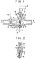
- a plasma electrode 3 of required polarity is formed of a needle having a tip of small curvature radius
- a plasma electrode 4 of opposite polarity is formed of a needle having a tip of large curvature radius.
- a high voltage from a DC power source 5 is applied between electrode 3 and electrode 5.
- a corona discharge of both polarities are generated between two electrodes.
- a plasma is formed at each of the tips of two electrodes.
- the intensity of an ionic current 6 of required polarity is higher than that of a current 7 of opposite polarity which is derived from the plasma electrode 4 of opposite polarity.
- the current 6 exists in a broad and long area.
- a powder 8 being carried by a gas as shown by arrow is agitated by a restriction 10 and a dispersing gas 11a issuing from a jet 11 of dispersing gas provided at the restriction 10 to disperse finely.
- Thus-obtained finely dispersed powder 12 is electrically charged during passing through a space 13 wherein mainly ions of required polarity exist.
- the charged powder 9 is obtained.
- the charge on the powder given by ionic current 6 of required polarity is scarcely neutralized by the ionic current 7 of opposite polarity, because the space 14 where mainly ions of opposite polarity exist is substantially separated from the conduit 2 by means 15 for keeping powder aloof from space 14, as shown by Figures 1 and 2. Moreover, these conditions are ensured by an adhesion-preventing gas 19 blown out from a jet 18 of gas provided around the plasma electrode 4 of opposite polarity.
- the used electrodes are corona discharge electrodes which generate plasma at their tips.
- a ring-formed jet 16 of gas is provided also around the plasma electrode 3 of required polarity, through which an adhesion-preventing gas 17 is blown out at high speed.
- Both adhesion-preventing gases 17 and 19 are principally for inhibiting any adhering of powder to tips of electrodes during the transient state when the starting of torch operation is stopped.
- FIG. 3 The embodiment shown in, Figure 3 is composed of a cylindrical body 1, made of insulating material, having circular section in which is formed a conduit 2 for conveying the powder 8 being carried by gas.
- a thin corona discharge electrode as plasma electrode 3 of required polarity is disposed along the axis of conduit 2, and thick corona discharge electrodes as plasma electrode 4 of opposite polarity are arranged on the peripheral wall of conduit 2 so as to confront the electrode of required polarity.
- the inner wall of conduit 2 in the part provided with plasma electrodes 4 converges upstream to associate with a restriction 10.
- a dispersing gas shown by arrow 11a is blown out of a ring-formed jet 11 for dispersing gas which is provided downstream, and maintains the tips of plasma electrodes of opposite polarity to be clean.
- the dispersing gas traverses the conduits 2, and agitates the powder to disperse finely.
- the resulting finely dispersed powder 12 is blown into a space 13 wherein mainly the ionic current 6 of required polarity derived from the tip of plasma electrodes 3 of required polarity exists, and is electrically charged.
- the ionic current 7 of opposite polarity derived from the plasma electrode 4 of opposite polarity is small in itself since the curvature radius of tip of electrode 4 is large.
- the restriction 10 is so constructed that the powder may be kept aloof from the space 7 wherein mainly ions of opposite polarity reside. Consequently, the neutralization of charges of required polarity on the powder with charges of opposite polarity.is suppressed. The total charging efficiency can be eventually increased.
- reference numeral 5 designates a DC power source for applying a DC voltage between both electrodes.
- Reference numeral 5a designates a high frequency power supply for feeding the power source 5.
- the adhesion-preventing gas 17 which has blown at high speed out of a jet 16 arranged around the tip of the plasma electrode of required polarity plays an important role in preventing the attachment of powder to the tip of the plasma electrode 3 of required polarity, especially in the transient state when the starting is stopped.
- Figure 4 shows an embodiment wherein plasma electrodes 3 of required polarity are arranged on the inner wall of the conduit 2 formed by a cylindrical body 1.
- the powder 8 carried by a gas is introduced tangentially in the conduit 2 upstream from the plasma electrodes 3 of required polarity by way of a powder-introducing conduit 1a.
- An adhesion-preventing gas 19 is admitted into the conduit through a jet 18 of gas formed around the plasma electrode 8 of opposite polarity.
- the powder 8 does not substantially pass to the space 14 wherein mainly an ionic current 7 of opposite polarity exist.
- an adhesion-preventing gas 19 Such as passing course of charged powder 9 is facilitated by an adhesion-preventing gas 19.
- charges on the powder given by ionic current 6 of required polarity are scarcely neutralized with ionic current 7 of opposite polarity.
- An adhesion-preventing gas can be blown out around the plasma electrode 3 of required polarity, if necessary.
- the strong revolving motion of powder-carrying gas by itself can inhibit any attachment of powder to the plasma electrode 3 of required polarity in the arrangement of the embodiment shown in Figure 4.
- Figure 5 shows a conduit 2 for conveying a powder B carried by gas, which is formed in the interior of a cylindrical body 1 made of insulating material having circular section.
- the plasma electrode 3 of required polarity which is composed of a needle electrode having a tip of small curvature radius is disposed along the axis of conduit 2, and a plasma electrode 4 of opposite polarity having a tip of large curvature radius is arranged along the axis, the latter electrode confronting the former.
- a DC high voltage is intended to be applied between both electrodes by means of a multi-stage booster circuit 5 and a high frequency power supply 5a.
- a ring-formed jet 11 of dispersing gas is arranged somewhat upstream from the midpoint. A dispersing gas 11a is blown into conduit 2 through the jet 11.
- a conduit 2 for conveying a powder 8 carried by gas is formed in the interior of a cylindrical body 1 made of insulating material having circular section.
- a needle electrode having a tip of large curvature radius as plasma electrode 4 of opposite polarity is arranged upstream inside the conduit 2 along its axis.
- a cone-shaped means 15 for keeping powder aloof from electrode 4 is provided immediately upstream from the electrode 4.
- a plasma electrode 3a of required polarity is arranged to confront the electrode 3a.
- the electrode 3a of required polarity is composed of two electrodes 3a-1 and 3a-2 which are adjacent to each other.
- Each of electrodes 3a-1 and 3a-2' is fed with its respective high DC voltage from its respective position of a DC power source via its respective protective resistance 31-1R or 3a-2R.
- the DC power source and two protective resistances are embedded in the cylindrical body. Due to the difference in DC voltage between electrodes 3a-1 and 3a-2, a plasma is always generated by a minute spark discharge. Whereby, a sufficient amount of ionic current of required polarity is always extracted from the plasma of the plasma electrode 4 of opposite polarity and proceeds toward the electrode 4 to form an area 13 wherein mainly ions of required plarity exist.
- Reference numeral 5a designates a high frequency power supply for feeding the DC power source 5.
- a plurality of jets 11 for blowing out revolving current of gas are formed to open into the conduit 2.
- a dispersing gas 11a is fed through jets 11 to agitate the powder 8 inthe conduits 2.
- the powder 8 is finely dispersed by agitation approaches the conduit wall and passes through the space 13 wherein mainly ions of required polarity exist.
- a powder 9 having charges of the same polarity is obtained.
- the charging of a powder can be stably performed with a high efficiency for a long period of time.
- a conduit 2 for conveying a powder 8 by gas is formed in a cylindrical body 1 made of insulating material having circular section.
- a needle electrode having a tip of small curvature radius as plasma electrode 3 of required polarity is disposed along the outlet side of axis of the conduit 2.
- a high voltage from a power source 5 is applied thereto, and an adhesion-preventing gas 17 is arranged to blow out of a jet 16 provided around the plasma electrode 3 of required polarity.
- a needle electrode 4 having a tip of large curvature radius as plasma electrode 4 of opposite polarity is disposed to confront the needle electrode 3.
- a hollow cone 15 is arranged for keeping the powder remote from the plasma of opposite polarity.
- An adhesion-preventing gas 19 is arranged to blow around the electrode 4 of opposite polarity through a jet 18.
- the powder passes through the part of plasma electrode of opposite polarity of conduit 2 without entering the area 4 wherein mainly ions of opposite polarity exist, and, thereafter, is agitated to finely disperse by a dispersing gas 11a blown out of a ring-formed jet 11 for dispersing gas.
- the finely dispersed powder is collected in the axial part of conduit 2 by the same dispersing gas, and enters the area 13 in which mainly ions of required polarity exist. Consequently, charging of powder is very efficiently performed without a substantial neutralization by charges from plasma electrode 4 of opposite polarity. Thus, a sufficiently charged powder 9 can be obtained.
- FIG. 9 illustrates an example in which charging of a powder is performed principally due to the effect given by the fact that the difference in volt-ampere characteristic between the plasma electrode 3 of required polarity and the plasma electrode 4 of opposite polarity is made great in operation.
- a conduit 2 for transferring a powder 8 carried by gas is formed in a cylindrical body 1 made of insulating material having circular section.
- a plasma electrode 3 of required polarity made of durable material having a tip of very small curvature radius is arranged along the axis of conduit 2. Confronting said electrode, an earthed plasma electrode 4 of opposite polarity having a tip of large curvature radius is disposed.
- a high DC voltage from a DC power source 5 is arranged to apply to the plasma electrode 3 of required polarity.
- a restriction 10 is provided upstream from the plasma electrode 4 of opposite polarity, and a dispersing gas 11a is made to blow out of a ring-formed jet 11 provided inthe part of restriction.
- Reference numeral 5a designates a high frequency power supply for feeding the DC high voltage circuit 5.
- the charged powder passes through an area 13 wherein an intense ionic current of required polarity exists, which is derived from the plasma electrode 13 of required polarity having a sufficiently large volt-ampere characteristic.
- an intense ionic current of required polarity exists, which is derived from the plasma electrode 13 of required polarity having a sufficiently large volt-ampere characteristic.
- charges on powder which has been given previously are neutralized and charges of required polarity are sufficiently given to the powder.
- the obtained charged powder is discharged outside as shown by arrow 9.
- the amount of powder to be treated or the selection of the polarity to be given may restrict the application of this embodiment.
- the structure in this embodiment is simple, the structure will suffice for the purpose of this invention as the case may be.
- the powder-dispersing means 10 and 11 employed in this embodiment can be omitted. It is intended that such a structure is also included in the scope of this invention.
- a conduit 2 for conveying a powder 8 carried by gas is formed within a cylindrical body 1 made of insulating material having circular section.
- a plasma electrode 3 of required polarity having a tip of very small curvature radius is arranged on the inside surface of conduit 2.
- a plasma electrode 4 of opposite polarity having a tip of large curvature radius is disposed also on the inside surface of conduit 2.
- a DC voltage from a DC power source 5 is arranged to apply between them.
- the earthing of one of electrodes is not always required, if necessary.
- the case wherein a voltage derived from a midway point of the powder source 5 is applied to one of electrodes as in this embodiment is also included in the scope of this invention.
- a jet 11 is provided on the inner surface of conduit 2 for blowing a dispersing gas 11a tangentially into the conduit.
- the powder is finely dispersed near the wall, passes first through an area 14, formed near the plasma electrode of opposite polarity, wherein mainly ions of opposite polarity exist, and then passes through an area 13 wherein mainly ions of required polarity exist.
- the curvature radius of tip of electrode is far different between both electrodes and the area 13 wherein mainly ions of required polarity exist is broader and more intense than the area 14 wherein mainly ions of opposite polarity exist, the powder as a whole acquires sufficient charges of required polarity.
- the obtained charged powder 9 is discharged out of the apparatus.
- Figure 11 illustrates a powder charging apparatus as an embodiment of this invention, which is preferably employed when a powder charging of high efficiency and large capacity is intended by increasing the plasma-generating performance of the plasma electrode of required polarity.
- a conduit 2 for transferring a powder 8 carried by gas is formed within a cylindrical body 1, made of insulating material, having circular section.
- a plasma-generating electrode of AC driving type as plasma electrode 3 of required polarity is disposed along the axis of conduit 2.
- This plasma electrode 3 of required polarity is composed of a thin tubular insulation 3Y made of ceramics etc. having the forward end closed into which a core electrode 3Z is inserted, the outside of said tubular insulation being wrapped with a coiled surface electrode 3X.
- a high AC voltage is applied between the core electrode 3Z and the surface electrode 3X by an AC power source 26 by way of a transformer.
- a DC voltage from a DC power source is applied thereto.
- a corona discharge electrode 4 having a tip of large curvature radius is usually disposed as plasma electrode of opposite polarity.
- An adhesion-preventing gas 19 can be blown out of jet 18 which is arranged around the corona discharge electrode 4 to prevent the powder from adhesion to the tip of electrode 4, if necessary.
- the corona discharge electrode 4 is earthed.
- a dispersing gas 11a is arranged to blow out of a ring-formed jet 11 which opens midway between both electrodes. Whereby, the powder transferred there is finely dispersed.
- a very intense AC plasma is generated arouno the surface electrode 3X because of a high AC voltage applied between the surface electrode 3X and the core electrode 3Z.
- a sufficiently large amount of ions of required polarity can be drawn from said plasma and an intense area 13 wherein mainly ions of required polarity exist is formed.
- this embodiment is preferred to realise a powder charging apparatus of high intensity and large capacity in accordance with this invention.
- FIG 12 illustrates one embodiment according to this invention wherein a conduit 2 for conveying a powder 8 carried by gas is formed in a cylindrical body 1 made of insulating material having circular section.
- This embodiment as a powder charging apparatus of this invention is characterised by being constructed by arranging a ring-formed AC plasma generating electrode for generating intense ions of required polarity along the interior surface of conduit 2 and arranging a plasma electrode 4 of opposite polarity which has a tip of large curvature radius and confronts said ring-formed electrode.
- a ring-formed insulation 3Y usually made of ceramic is provided along the inside surface of conduit 2.
- a surface electrode 3X composed of thin wire is arranged along the inner surface of insulation 3X.
- a ring electrode 3Z of broad ribbon form is arranged along the back surface of insulation 3X.
- An AC power source 26 is so connected that an AC high voltage is applied between electrodes 3Y and 3Z by way of a transformer 26.
- a DC power source 5 is connected to raisethe potential as a whole of both electrodes impressed with AC voltage.
- the plasma electrode 4 of opposite polarity is earthed via a conductor 21.
- An adhesion-preventing gas 19 is arranged to blow out of a jet 18 provided around the plasma electrode 4 of opposite polarity.
- a dispersing gas 11 a is arranged to blow out midway between both electrodes by means of a jet 11 for injecting dispersing gas. Whereby, the powder is finely dispersed and passes near the inside wall of conduit.
- a very intense AC plasma is generated around the electrode 3X by an action of a high AV voltage applied between electrodes 3X and 3Z.
- a very large amount of ion of required polarity is continuously drawn from the AC plasma to go toward the plasma electrode of opposite polarity, by virtue of a DC electric field directed toward the plasma electrode of opposite polarity, which is generated by the DC power source 5.
- the finely dispersed powder which approaches the conduit wall and passes near the electrode can be electrically charged to be discharged outside as a very intensely charged powder 9.
- This system constitutes an embodiment of this invention, which can be advantageously employed when a large amount of powder having a high charge density is desired to obtain.
- a corona discharge electrode having a tip of small curvature radius or an AC plasma generating electrode is primarily employed as plasma electrode of required polarity, and a corona discharge needle electrode having a tip of relatively large curvature radius is employed as plasma electrode of opposite polarity.
- a restriction in conduit, a dispersing gas, or a revolving gas flow is employed as means for dispersing the powder.
- a baffle alsomay be used.
- Means for preventing the adhesion and the accumulation of the powder on both electrodes can be selected from the group consisting of a system of blowing out of gas for enveloping the electrode, a system of utilising of a plasma generating electrode of AC driving type, or a combination thereof to apply, depending on the object.
- FIG. 13 illustrates one embodiment according to the present invention wherein a conduit 2 for transferring a powder 8 carried by gas is formed in a cylindrical body 1 made of insulating material having circular section.
- a needle electrode 3 surrounded by jet 16 for blowing out an adhesion-preventing gas 17 is arranged along the axis of conduit as plasma electrode of required polarity.
- a plasma electrode 4 of opposite polarity which is surrounded by jet 18 for blowing out an adhesion-preventing gas 19 is arranged along the axis.
- a high DC voltage is arranged to apply between these electrodes by means of a multistage booster circuit 5 and a high frequency power supply 5a.
- a ring-formed jet 11 is disposed somewhat upstream from the midpoint between both electrodes and a dispersing gas 11 a is arranged to blowout of said jet 11 into said conduit 2.
- the powder can be charged substantially only by ions of required polarity with preventing the neutralization of charges on powder with ions of opposite polarity.
- Thus-obtained charged powder 9 is stable for a long time.
- special means merely for keeping the powder aloof from the area wherein ions of opposite polarity exist is provided, such special means is not provided in the case of the embodiment shown in Figure 13. However, it does not mean that the prevention of powder passing through area 14 is not contemplated in the embodiment of Figure 13.
- the use of the powder charging apparatus according to this invention in an electrostatic powder coating apparatus is explained in detail.
- the essential constituents of this invention such as plasma electrodes, means for dispersing the powder and means for keeping the powder aloof from the area wherein mainly ions of opposite polarity exist, can be suitably selected and combined to employ, depending on the object of application.
- FIG 14 shows an embodiment wherein a powder charging apparatus according to this invention is employed to construct an electrostatic powder coating apparatus with excellent throwing power.
- a conduit 2 for conveying a powder 8 carried by gas is formed in a cylindricalbody 1 made of insulating material having a circular section.
- a needle electrode having a tip of small curvature radius as plasma electrode 3 of required polarity is disposed near the forward end of conduit 2. Confronting the needle electrode, a needle-formed corona discharge electrode having a tip of large curvature radius is disposed as plasma electrode 4 of opposite polarity.
- a high DC voltage is applied between both electrodes by means of a DC power source 5 and said plasma electrode 3 of required polarity is earthed via a conductor 20.
- Reference numeral 5a designates a high frequency power supply for feeding the DC power source 5.
- a restriction 10 for example, can be provided upstream from the plasma electrode 4 of opposite polarity, if necessary.
- the powder in finely dispersed state passes first through a space wherein mainly ions of opposite polarity exist.
- the powder passes through a space wherein mainly ions of required polarity are present, and is discharged as intensely charged powder 9 from the outlet at the forward end of conduit.
- a distributing plate 28 is provided for modifying the pattern of distribution of discharged powder, whereby the pattern of distribution can have a suitable spread.
- a pattern-modifying gas shown by arrow 30 is made to blow out of a jet 29 for blowing out pattern-modifying gas.
- Reference numeral 31 designates a substrate.
- the end of thus constructed electrostatic powder coating apparatus of this invention is maintained to be earthed by a wire 20, no electric field is generated between said end and the substrate.
- the powder 9 blown out of the forward end of electrostatic powder coating apparatus is sprayed onto the substrate, no so- called Faraday cage effect arises, in contrast to the common electrostatic powder coating apparatus wherein due to the effect of electric field being directed from the tip of gun to the substrate, the deposition of coating material is concentrated to places of intense electric field and is scarecely performed at depressed areas.
- an electrostatic powder coating can be conducted with excellent throwing power. Further, when the powder is charged in excess and the forward end of gun has no electric charge, the powder is distributed too broadly, due to the mutual repulsion of charged particles, to enter narrow spaces.
- the wire 20 is connected to a terminal of the power source 5 having a suitably high DC potential to generate a weak electric field between the gun and the substrate.
- adhesion-preventing gases 17 and 19 are used, as in the case of other embodied electrostatic powder coating apparatus mentioned above.
- FIG 15 illustrates an electrostatic powder coating apparatus implemented with a powder charging apparatus of this invention, which is preferred when an electrostatic powder coating is intended to obtain a thick coating.
- a conduit 2 for conveying a powder 8 carried by gas is formed in a cylindrical body 1 made of insulating material having circular section.
- a short conduit 22 including device 29 for modifying the pattern of distribution of powder is attached to the forward end of conduit 2 so that the axis of short conduit maybe in alignment with the axis of conduit 2.
- a corona discharge electrode 3 having a tip of very small curvature radius as plasma electrode of required polarity is disposed upstream from said short conduit 22. Confronting the electrode 3, a plasma electrode 4 of opposite polarity having a tip of relatively large corvature radius is disposed and is earthed.
- a high DC voltage from a DC power source 5 is applied to the plasma electrode 3 of required polarity.
- Reference numeral 5a designates a high frequency power supply for feeding the high DC power source 5, Further, means for dispersing the powder, such as restriction 10, is arranged between electeode 3 and electrode 4, as detailed hereinbefore.
- the flow rate of a pattern-modifying gas shown by arrow 30 is regulated.
- Reference numerals 31 and 16 designate a substrate and a jet for blowing out an adhesion-preventing gas 17, respectively.
- the adhesion-preventing gas is for preventing adhering of powder to the tip of plasma electrode of required polarity.
- the finely dispersed powder is sufficiently charged between the plasma electrode of required polarity and the plasma electrode of opposite polarity as detailed herein before, and is sprayed onto a substrate through the short conduit 22.
- the plasma electrode of required polarit to which a high voltage is applied is near the discharging outlet, an intense DC field being directed to the substrate is generated, the charged powder proceeds to substrate by the action of this electric field to deposit.
- an ionic current being directed from the forward end of the electrostatic powder coating apparatus to substrate do not exist at the surface of substrate. Accordingly, a backward ionization can hardly arise and only the electric field exists. Therefore, the depositing efficiency can be maintained to be high.
- the electrostatic powder coating can be practiced to obtain a thick coating, without backward ionization.
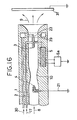
- FIG 16 shows an electrostatic powder coating apparatus of high performance, as one embodiment of this invention, which is constructed by employing a powder charging apparatus according to this invention wherein the electrostatic powder coating can be performed with very high depositing efficiency and excellent throwing powder.
- a conduit 2 for conveying a powder 8 carried by gas is formed within a cylindrical body 1 made of insulating material having circular section.
- a plasma electrode 3 of required polarity is arranged along the axis of conduit 2 near the outlet thereof and a high voltage from a power source 5 is applied to the electrode.
- A, substrate-confronting corona electrode 23 which is connected to the electrode 3 is arranged to be directed toward the outlet.
- a corona discharge electrode 4 having a tip of relatively large curvature radius as plasma electrode 4 of opposite polarity is disposed as can be seen in the drawing and is earthed by a conductor 21.
- Reference numeral 5a designates a high frequency power supply for feeding the DC power source 5.
- An adhesion-preventing gas shown by arrow 1 7 is used for preventing the tip of plasma electrode of required polarity and that of substrate-confronting corona electrode 23 from adhering of powder.
- a pattern modifying gas shown by arrow 30 is blown out of jet of the device 29 for modifying the pattern of distribution of powder, which opens near the end of conduit 2, to form a revolving flow.
- the pattern of distribution of the charged powder 9 which is blown out of the electrostatic powder coating apparatus can be regulated by modifying the amount of the gas blown out of jet of the device 29.
- the powder is intensely charged between the plasma electrode 3 of required polarity and the plasma electrode 4 of opposite polarity to have the same polarity with that of the plasma electrode 3 due to the powder charging mechanism detailed hereinbefore.
- the powder is again charged by corona discharge as well as the intense field which is generated to be directed from the tip of the substrate-confronting corona electrode 23 to the substrate.
- the electrostatic powder coating can be performed with very high efficiency and high throwing power.
- an electrostatic powder coating apparatus having a high performance is obtained in accordance with this invention.
- the essential consitituents detailed above of the powder charging apparatus of this invention can be suitably selected as practical means and combined to employ, depending on the object of application. Besides the above-mentioned methods for forming of pattern of distribution and modifying thereof, all commonly known means and methods can be applied. These situations are encountered in embodiments shown in Figures 13 and 14.
- FIG 17 illustrates an electrostatic powder coating apparatus, as one embodiment of this invention, which is constructed by using a powder charging apparatus according to this invention, wherein the electrostatic powder coating can be conducted with the depositing efficiency in harmony with the throwing power.
- a conduit 2 for conveying a powder 8 carried by gas is formed in a cylindrical body 1 made of insulating material having circular section.
- a substrat-confronting corona electrode 23 which is directed to and confronts a substrate 31 is disposed along the axis of conduit near the outlet thereof.
- a plasma electrode 3 of required polarity is arranged upstream and somewhat distant from the electrode 23. The highest voltage of a power source 5 is applied to the electrode 3 and an intermediate voltage is applied to the substrate-confronting corona electrode 23.
- a plasma electrode 4 of opposite polarity which is disposed the most upstream is earthed.
- charging of the powder is conducted between the electrode 4 and the electrode 3 as in other embodiments.
- the intermediate voltage applied to the electrode 23 is selected to generate an electric field in such a degree as to promote suitably the running of powder 9 toward the substrate without deteriorating the throwing power of charged powder flow 9.
- needle electrodes or plasma generating electrodes of AC driving type are employed as plasma generating electrode of required or opposite polarity, for illustrating.
- other electrode capable of generating plasma such as thin wire of knife edge form, can be used.
- an electrode of AC driving type is employed as the electrode of opposite polarity of this invention.
- each of electrode couple employed for charging the powder is a needle electrode, a knife edge electrode, a wire electrode, or a plasma generating electrode of AC driving type, which always repel intensely the powder in operation, no powder adheres to and accumulates on each electrode in operation.
- a stable operation of the apparatus can be secured amidst powder for a long time.
- a high and stable performance of the apparatus can be maintained irrespective of material properties of the powder.
- novel electrostatic powder coating apparatuses which are remarkably excellent in throwing power, depositing efficiency and performance for obtaining thick coating can be completed. These apparatuses are stably operated for a long period of time. Even when the apparatus is without applied external electric field and external ionic current, the aforementioned electrostatic powder coating apparatus is also very useful. It is considered almost impossible in the prior art that such an electrostatic powder coating apparatus is stably operated for a long time with high efficiency, irrespective of material properties of powdered coating material.
- one electrode of electrode couple used for charging the powder is a corona discharge electrode 43 as shown in Figures 18 and 19, and the other electrode is a substantially smooth cylindrical electrode 44 in the powder charging apparatus of the prior art shown by Figure 18 or 19.
- a high voltage is applied between both electrodes and only a unipolar ionic current of required polarity flows from the corona discharge electrode 43 to the cylindrical electrode 44. Accordingly, particles of powder essentially tend to adhere to and accumulate on the surface of cylindrical electrode 44. Once particles of powder adhere even if in minute amount, they cause the backward ionization from which an ionic current of opposite polarity flows backward to the corona discharge electrode 43 to neutralize ions or charges of required polarity.
Landscapes
- Electrostatic Spraying Apparatus (AREA)
Applications Claiming Priority (2)
| Application Number | Priority Date | Filing Date | Title |
|---|---|---|---|
| JP25828985A JPH0636890B2 (ja) | 1985-11-18 | 1985-11-18 | 粉体荷電装置および静電粉体塗着装置 |
| JP258289/85 | 1985-11-18 |
Publications (3)
| Publication Number | Publication Date |
|---|---|
| EP0230723A2 true EP0230723A2 (fr) | 1987-08-05 |
| EP0230723A3 EP0230723A3 (en) | 1987-10-14 |
| EP0230723B1 EP0230723B1 (fr) | 1991-07-17 |
Family
ID=17318185
Family Applications (1)
| Application Number | Title | Priority Date | Filing Date |
|---|---|---|---|
| EP19860308890 Expired EP0230723B1 (fr) | 1985-11-18 | 1986-11-14 | Appareil pour le chargement de poudre et de revêtement électrostatique à l'aide de cette poudre |
Country Status (3)
| Country | Link |
|---|---|
| EP (1) | EP0230723B1 (fr) |
| JP (1) | JPH0636890B2 (fr) |
| DE (1) | DE3680316D1 (fr) |
Cited By (4)
| Publication number | Priority date | Publication date | Assignee | Title |
|---|---|---|---|---|
| DE19542863A1 (de) * | 1995-11-17 | 1997-05-22 | Abb Research Ltd | Pulversprüheinrichtung |
| GB2312298A (en) * | 1996-04-16 | 1997-10-22 | Samsung Display Devices Co Ltd | Multiple charged developer gun |
| RU2127639C1 (ru) * | 1996-04-23 | 1999-03-20 | Военный автомобильный институт | Способ окраски изделий в электростатическом поле |
| CN112695268A (zh) * | 2021-01-14 | 2021-04-23 | 四川大学 | 一种用于超音速等离子喷涂的环形送粉和气体聚焦装置 |
Families Citing this family (2)
| Publication number | Priority date | Publication date | Assignee | Title |
|---|---|---|---|---|
| AU777167B2 (en) * | 1999-04-23 | 2004-10-07 | Battelle Memorial Institute | Directionally controlled EHD aerosol sprayer |
| DE102005045176A1 (de) * | 2005-09-21 | 2007-03-22 | Ramseier Technologies Ag | Applikator |
Citations (1)
| Publication number | Priority date | Publication date | Assignee | Title |
|---|---|---|---|---|
| DE2646798A1 (de) | 1976-10-16 | 1978-04-20 | Haug & Co Kg | Vorrichtung zur elektrischen aufladung von fluessigen oder festen teilchen in einem gasstrom |
Family Cites Families (2)
| Publication number | Priority date | Publication date | Assignee | Title |
|---|---|---|---|---|
| US4135667A (en) * | 1977-03-23 | 1979-01-23 | Hajtomuvek Es Festoberendezesek Gyara | Apparatus for the electrostatic coating of workpieces |
| JPS5534159A (en) * | 1978-09-01 | 1980-03-10 | Onoda Cement Co Ltd | Powder charging device and electrostatic powder depositing device |
-
1985
- 1985-11-18 JP JP25828985A patent/JPH0636890B2/ja not_active Expired - Lifetime
-
1986
- 1986-11-14 DE DE8686308890T patent/DE3680316D1/de not_active Expired - Lifetime
- 1986-11-14 EP EP19860308890 patent/EP0230723B1/fr not_active Expired
Patent Citations (1)
| Publication number | Priority date | Publication date | Assignee | Title |
|---|---|---|---|---|
| DE2646798A1 (de) | 1976-10-16 | 1978-04-20 | Haug & Co Kg | Vorrichtung zur elektrischen aufladung von fluessigen oder festen teilchen in einem gasstrom |
Cited By (6)
| Publication number | Priority date | Publication date | Assignee | Title |
|---|---|---|---|---|
| DE19542863A1 (de) * | 1995-11-17 | 1997-05-22 | Abb Research Ltd | Pulversprüheinrichtung |
| GB2312298A (en) * | 1996-04-16 | 1997-10-22 | Samsung Display Devices Co Ltd | Multiple charged developer gun |
| US5907469A (en) * | 1996-04-16 | 1999-05-25 | Samsung Display Devices Co., Ltd. | Multiple charged developing gun |
| GB2312298B (en) * | 1996-04-16 | 2000-09-20 | Samsung Display Devices Co Ltd | Developing gun with multiple electrodes |
| RU2127639C1 (ru) * | 1996-04-23 | 1999-03-20 | Военный автомобильный институт | Способ окраски изделий в электростатическом поле |
| CN112695268A (zh) * | 2021-01-14 | 2021-04-23 | 四川大学 | 一种用于超音速等离子喷涂的环形送粉和气体聚焦装置 |
Also Published As
| Publication number | Publication date |
|---|---|
| JPH0636890B2 (ja) | 1994-05-18 |
| EP0230723B1 (fr) | 1991-07-17 |
| DE3680316D1 (de) | 1991-08-22 |
| JPS62117651A (ja) | 1987-05-29 |
| EP0230723A3 (en) | 1987-10-14 |
Similar Documents
| Publication | Publication Date | Title |
|---|---|---|
| US4788933A (en) | Electrostatic spraying device for spraying articles with powdered material | |
| US4289278A (en) | Powder electro-charging device and electrostatic powder painting device | |
| US4114810A (en) | Electrostatic powder painting apparatus | |
| US4039145A (en) | Electrostatic powdering nozzle | |
| US4805069A (en) | Powder charging apparatus and electrostatic powder painting apparatus | |
| US3248606A (en) | Apparatus for dispersing and electrically charging substances in discrete particulate form | |
| US4171100A (en) | Electrostatic paint spraying apparatus | |
| CA1336130C (fr) | Pistolet pulverisateur avec charge electrocinetique de matiere pulverulente | |
| FI64059C (fi) | Foerfarande och anordning foer kontinuerlig elektrogasdynamiskbelaeggning av en serie arbetsstycken | |
| JPH07107876B2 (ja) | プラズマ発生装置及びプラズマ発生方法 | |
| CZ112486A3 (en) | Process and apparatus for applying coatings to articles by liquid spraying | |
| US6458427B2 (en) | Annular flow electrostatic powder coater | |
| JPH0673646B2 (ja) | 摩擦電気粉末帯電による静電粉末噴射装置 | |
| JPH0525552B2 (fr) | ||
| US3540653A (en) | Apparatus for dispersing and electrically charging substances in discrete particulate form | |
| US7240861B2 (en) | Method and apparatus for dispensing paint powders for powder coatings | |
| US4706890A (en) | Method and apparatus for electrostatic coating of articles with powdered coating material | |
| US4084019A (en) | Electrostatic coating grid and method | |
| US4772982A (en) | Powder charging apparatus and electrostatic powder coating apparatus | |
| EP0230723B1 (fr) | Appareil pour le chargement de poudre et de revêtement électrostatique à l'aide de cette poudre | |
| KR19980087013A (ko) | 정전분체 도장건 | |
| JPS5930468B2 (ja) | 粉粒体の帯電方法およびその装置 | |
| JPH02503648A (ja) | 導電性被覆液用吹付け被覆装置 | |
| Kleber | Electrostatic powder gun design | |
| US5843536A (en) | Coating material dispensing and charging system |
Legal Events
| Date | Code | Title | Description |
|---|---|---|---|
| PUAI | Public reference made under article 153(3) epc to a published international application that has entered the european phase |
Free format text: ORIGINAL CODE: 0009012 |
|
| AK | Designated contracting states |
Kind code of ref document: A2 Designated state(s): CH DE FR GB LI SE |
|
| PUAL | Search report despatched |
Free format text: ORIGINAL CODE: 0009013 |
|
| AK | Designated contracting states |
Kind code of ref document: A3 Designated state(s): CH DE FR GB LI SE |
|
| 17P | Request for examination filed |
Effective date: 19880217 |
|
| 17Q | First examination report despatched |
Effective date: 19880905 |
|
| GRAA | (expected) grant |
Free format text: ORIGINAL CODE: 0009210 |
|
| AK | Designated contracting states |
Kind code of ref document: B1 Designated state(s): CH DE FR GB LI SE |
|
| REF | Corresponds to: |
Ref document number: 3680316 Country of ref document: DE Date of ref document: 19910822 |
|
| ET | Fr: translation filed | ||
| PLBE | No opposition filed within time limit |
Free format text: ORIGINAL CODE: 0009261 |
|
| STAA | Information on the status of an ep patent application or granted ep patent |
Free format text: STATUS: NO OPPOSITION FILED WITHIN TIME LIMIT |
|
| 26N | No opposition filed | ||
| REG | Reference to a national code |
Ref country code: GB Ref legal event code: 732 |
|
| REG | Reference to a national code |
Ref country code: CH Ref legal event code: PUE Owner name: I.T.M. CORPORATION |
|
| REG | Reference to a national code |
Ref country code: FR Ref legal event code: TP |
|
| EAL | Se: european patent in force in sweden |
Ref document number: 86308890.2 |
|
| PGFP | Annual fee paid to national office [announced via postgrant information from national office to epo] |
Ref country code: GB Payment date: 19960924 Year of fee payment: 11 |
|
| PGFP | Annual fee paid to national office [announced via postgrant information from national office to epo] |
Ref country code: SE Payment date: 19961118 Year of fee payment: 11 |
|
| PGFP | Annual fee paid to national office [announced via postgrant information from national office to epo] |
Ref country code: FR Payment date: 19961129 Year of fee payment: 11 |
|
| REG | Reference to a national code |
Ref country code: CH Ref legal event code: PFA Free format text: I.T.M. CORPORATION TRANSFER- RID CORPORATION |
|
| PGFP | Annual fee paid to national office [announced via postgrant information from national office to epo] |
Ref country code: DE Payment date: 19970127 Year of fee payment: 11 |
|
| PGFP | Annual fee paid to national office [announced via postgrant information from national office to epo] |
Ref country code: CH Payment date: 19970204 Year of fee payment: 11 |
|
| REG | Reference to a national code |
Ref country code: FR Ref legal event code: CD Ref country code: FR Ref legal event code: CA |
|
| PG25 | Lapsed in a contracting state [announced via postgrant information from national office to epo] |
Ref country code: GB Free format text: LAPSE BECAUSE OF NON-PAYMENT OF DUE FEES Effective date: 19971114 |
|
| PG25 | Lapsed in a contracting state [announced via postgrant information from national office to epo] |
Ref country code: SE Free format text: LAPSE BECAUSE OF NON-PAYMENT OF DUE FEES Effective date: 19971115 |
|
| PG25 | Lapsed in a contracting state [announced via postgrant information from national office to epo] |
Ref country code: LI Free format text: LAPSE BECAUSE OF NON-PAYMENT OF DUE FEES Effective date: 19971130 Ref country code: FR Free format text: THE PATENT HAS BEEN ANNULLED BY A DECISION OF A NATIONAL AUTHORITY Effective date: 19971130 Ref country code: CH Free format text: LAPSE BECAUSE OF NON-PAYMENT OF DUE FEES Effective date: 19971130 |
|
| GBPC | Gb: european patent ceased through non-payment of renewal fee |
Effective date: 19971114 |
|
| REG | Reference to a national code |
Ref country code: CH Ref legal event code: PL |
|
| PG25 | Lapsed in a contracting state [announced via postgrant information from national office to epo] |
Ref country code: DE Free format text: LAPSE BECAUSE OF NON-PAYMENT OF DUE FEES Effective date: 19980801 |
|
| EUG | Se: european patent has lapsed |
Ref document number: 86308890.2 |
|
| REG | Reference to a national code |
Ref country code: FR Ref legal event code: ST |