EP0230800A1 - Mischventile - Google Patents
Mischventile Download PDFInfo
- Publication number
- EP0230800A1 EP0230800A1 EP86402615A EP86402615A EP0230800A1 EP 0230800 A1 EP0230800 A1 EP 0230800A1 EP 86402615 A EP86402615 A EP 86402615A EP 86402615 A EP86402615 A EP 86402615A EP 0230800 A1 EP0230800 A1 EP 0230800A1
- Authority
- EP
- European Patent Office
- Prior art keywords
- plate
- ball joint
- valve according
- valve
- center
- Prior art date
- Legal status (The legal status is an assumption and is not a legal conclusion. Google has not performed a legal analysis and makes no representation as to the accuracy of the status listed.)
- Granted
Links
- 239000000919 ceramic Substances 0.000 claims abstract description 13
- 241000826860 Trapezium Species 0.000 claims abstract description 9
- PNEYBMLMFCGWSK-UHFFFAOYSA-N aluminium oxide Inorganic materials [O-2].[O-2].[O-2].[Al+3].[Al+3] PNEYBMLMFCGWSK-UHFFFAOYSA-N 0.000 claims description 3
- 238000004891 communication Methods 0.000 claims description 2
- 230000000295 complement effect Effects 0.000 claims description 2
- 238000005245 sintering Methods 0.000 claims description 2
- XLYOFNOQVPJJNP-UHFFFAOYSA-N water Substances O XLYOFNOQVPJJNP-UHFFFAOYSA-N 0.000 description 21
- 239000000203 mixture Substances 0.000 description 5
- 230000008878 coupling Effects 0.000 description 4
- 238000010168 coupling process Methods 0.000 description 4
- 238000005859 coupling reaction Methods 0.000 description 4
- 239000000463 material Substances 0.000 description 2
- 239000002991 molded plastic Substances 0.000 description 2
- 235000012431 wafers Nutrition 0.000 description 2
- QHFVYZUHGGZWCC-UHFFFAOYSA-J S([O-])(O)=O.[Mo+4].S([O-])(O)=O.S([O-])(O)=O.S([O-])(O)=O Chemical compound S([O-])(O)=O.[Mo+4].S([O-])(O)=O.S([O-])(O)=O.S([O-])(O)=O QHFVYZUHGGZWCC-UHFFFAOYSA-J 0.000 description 1
- 238000005553 drilling Methods 0.000 description 1
- 239000013536 elastomeric material Substances 0.000 description 1
- 239000011521 glass Substances 0.000 description 1
- 229910052751 metal Inorganic materials 0.000 description 1
- 239000002184 metal Substances 0.000 description 1
- 238000000034 method Methods 0.000 description 1
- 230000004048 modification Effects 0.000 description 1
- 238000012986 modification Methods 0.000 description 1
- 239000004033 plastic Substances 0.000 description 1
- 238000007789 sealing Methods 0.000 description 1
- 230000035945 sensitivity Effects 0.000 description 1
- 230000003584 silencer Effects 0.000 description 1
Images


Classifications
-
- F—MECHANICAL ENGINEERING; LIGHTING; HEATING; WEAPONS; BLASTING
- F16—ENGINEERING ELEMENTS AND UNITS; GENERAL MEASURES FOR PRODUCING AND MAINTAINING EFFECTIVE FUNCTIONING OF MACHINES OR INSTALLATIONS; THERMAL INSULATION IN GENERAL
- F16K—VALVES; TAPS; COCKS; ACTUATING-FLOATS; DEVICES FOR VENTING OR AERATING
- F16K11/00—Multiple-way valves, e.g. mixing valves; Pipe fittings incorporating such valves
- F16K11/02—Multiple-way valves, e.g. mixing valves; Pipe fittings incorporating such valves with all movable sealing faces moving as one unit
- F16K11/06—Multiple-way valves, e.g. mixing valves; Pipe fittings incorporating such valves with all movable sealing faces moving as one unit comprising only sliding valves, i.e. sliding closure elements
- F16K11/078—Multiple-way valves, e.g. mixing valves; Pipe fittings incorporating such valves with all movable sealing faces moving as one unit comprising only sliding valves, i.e. sliding closure elements with pivoted and linearly movable closure members
- F16K11/0782—Single-lever operated mixing valves with closure members having flat sealing faces
-
- Y—GENERAL TAGGING OF NEW TECHNOLOGICAL DEVELOPMENTS; GENERAL TAGGING OF CROSS-SECTIONAL TECHNOLOGIES SPANNING OVER SEVERAL SECTIONS OF THE IPC; TECHNICAL SUBJECTS COVERED BY FORMER USPC CROSS-REFERENCE ART COLLECTIONS [XRACs] AND DIGESTS
- Y10—TECHNICAL SUBJECTS COVERED BY FORMER USPC
- Y10T—TECHNICAL SUBJECTS COVERED BY FORMER US CLASSIFICATION
- Y10T137/00—Fluid handling
- Y10T137/8593—Systems
- Y10T137/86493—Multi-way valve unit
- Y10T137/86549—Selective reciprocation or rotation
-
- Y—GENERAL TAGGING OF NEW TECHNOLOGICAL DEVELOPMENTS; GENERAL TAGGING OF CROSS-SECTIONAL TECHNOLOGIES SPANNING OVER SEVERAL SECTIONS OF THE IPC; TECHNICAL SUBJECTS COVERED BY FORMER USPC CROSS-REFERENCE ART COLLECTIONS [XRACs] AND DIGESTS
- Y10—TECHNICAL SUBJECTS COVERED BY FORMER USPC
- Y10T—TECHNICAL SUBJECTS COVERED BY FORMER US CLASSIFICATION
- Y10T137/00—Fluid handling
- Y10T137/8593—Systems
- Y10T137/86493—Multi-way valve unit
- Y10T137/86815—Multiple inlet with single outlet
Definitions
- the invention relates to a mixing valve for mixing two flows and more particularly intended for the sanitary field, for mixing hot water and cold water.
- the invention relates more particularly to the field of valves of a particular type where the elements producing the mixture are ceramic plates having polished surfaces in contact and movable relative to one another.
- the ceramic plates generally have duct elements communicating from one plate to the other, so that the passage section of the two flows is made adjustable before their actual mixing, by the positioning of the two plates.
- Known systems very generally comprise a fixed ceramic plate and a movable ceramic plate, the position of which is varied by means of a single lever-shaped control, movable in two movements corresponding respectively, for the user, to the adjustment the flow of mixed water and the adjustment of the ratio of the two flows in said mixture.
- a first object of the invention is to propose a valve with polished plates, actuated by a single lever and the two settings of which are truly independent.
- the known devices are provided with plates pierced in such a way that, for the most part, the two flows of hot and cold water pass through the fixed plate, mix at the level of the mobile plate without passing through it and this mixture being evacuated to an outlet substantially parallel to the two inlets, generally via an additional orifice in the fixed plate.
- This path of the water in the valve and in particular the complete change of direction which takes place between the fixed and mobile plates, is very generally the cause of relatively annoying operating noises, so that many valves of this kind are provided anti-noise screen, which also has the major disadvantage of clog very quickly.
- Another object of the invention is to provide a device having a low level of operating noise, without a screen, in particular due to the fact that the mixed water can be discharged laterally along the contour of the movable plate, which does not include no duct element, the characteristics of the two settings of flow and mixing respectively, being obtained by the very shape of said contour.
- the invention essentially relates to a mixing valve for mixing two flows, comprising a body containing two plates each having a flat and smooth face, these flat faces being in contact with one another, one plates being fixed and having two orifices respectively in communication with inlet conduits of the two flows and the other plate being movable and coupled to a ball joint lever, a lateral outlet being arranged in the vicinity of the edge of the movable plate, characterized in that said ball joint lever is subject to move in a predetermined pivoting direction defined by a fixed guide groove with respect to said body, with the possibility of rotation on its axis, of a predetermined amplitude for any position the along said pivoting direction, the two extreme positions of rotation being determined by at least one stop of said lever cooperating with the edges of said groove re and in that said movable plate, coupled to said ball joint lever by an offset offset thereof, has the approximate shape of a trapezoid with rounded ends.
- the plates defined above are preferably ceramic plates or "mirrors" respectively comprising smooth surfaces in contact to ensure the distribution and the mixing of the two aforementioned flows. It is quite obvious, however, that the invention in fact covers any wafer device whose shapes and mounting correspond to the above definition, even if these wafers are not made of ceramic, but of a material whose state of surface and mechanical characteristics make it possible to obtain results which are substantially equivalent, or even worse, in terms of sealing on closing, in particular.
- said rounded ends are portions of circles, the radii and the positions of these circles being deduced from the "kinematics" imposed on the movable plate by the aforementioned rotary lever, as will appear clearly further.
- a mixing valve 11 comprising a body 12, for example of molded plastic, intended to be inserted into a suitable cavity of a tap 13 sketched in phantom in Figure 2.
- the two hot and cold water flows are respectively introduced into the body by two inlets 14 and 15 located at the lower part of the body (considering figure 2), while a wide lateral outlet 16 of mixed water s opens next to the tap outlet duct 13.
- the valve body 12 is shaped to present, at its upper part, a guide groove curve 17 opening into a portion of cavity 18a with a spherical surface, provided for the articulation of a ball joint lever 19.
- the body 12 furthermore houses and in order, said ball joint lever 19, engaged in the groove 17, an internal base 20, fixed inside said body and shaped in particular to define the other portion of cavity 18b with a spherical surface in which the ball joint 19a of the lever 19 is articulated, a coupling part 22 with a thin wall, made of material self-lubricating, an operating plate 23, a movable plate 24 in ceramic, a fixed plate 25 in ceramic, and a bottom wall 26 fixed to said body and comprising in its thickness two holes for the cold water and Hot water.
- Each hole houses a metal connection ring 28, surrounded by a tubular seal 29 made of rubber or equivalent elastomeric material.
- the "ceramic" of the plates 24 and 25 is, preferably alumina oxide; the shape of the plates is obtained by sintering.
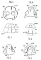
- the fixed plate 25 has approximately the shape of a disc comprising, along its circular edge, notches 32 cooperating with internal lateral projections of said body 12, for the immobilization of said fixed plate in said body.
- the seals 29 are applied in a sealed manner around the lower orifices of two inclined conical holes 35 extending in the thickness of the fixed plate 25 and whose upper circular orifices 30 and 31 (respectively for hot water and the cold water) open onto the smooth face of the movable plate 24.
- the two orifices 30 and 31 are spaced apart by a chosen distance and have a predetermined diameter. As will be seen later, this spacing distance and this diameter are important parameters in determining the shape and dimensions of the movable plate.
- the movable plate 24 is in contact by its smooth face shown in Figure 4 with the fixed plate 25 shown in Figure 3. It has no drilling.
- the variable closure of the orifices 30 and 31 is determined by the special contour of the plate 24.
- the opposite face of the latter (FIG. 5) has a relief defined by two lateral clearances 38.
- a complementary relief materialized by two embedding cheeks 39 is formed on the maneuvering plate 23.
- the latter made of molded plastic, thus naturally fits onto the movable plate 24.
- the maneuvering plate has a cavity 40 in which is engaged a projection 42 projecting from the lower part of the ball 19a.
- the projection 41 is offset with respect to the lever 19.
- the face 42 of the maneuvering plate 23 opposite the movable plate has a guide rib 43 provided with a rounded enlargement 44 engaged in a fixed groove 45 defined on the lower face ( always considering FIG. 2) of the internal base 20.
- the coupling piece 22 (made of plastic loaded with molybdenum bisulfite) is shaped to cover the edges and the internal wall of the cavity 40, as well as the rib 43 and its widening rounded 44, in particular the sides thereof. To this end, it comprises a tubular portion 40a and a skirt 44a with a curved profile.
- the sides of the operating plate 23 have cantilevered surfaces 46, extending the embedding cheeks 39.
- the ball joint lever 19 is subject to move in a predetermined pivoting direction defined by the groove 17, the pivot center being that of the ball joint 19a.
- the lever is also mounted with the possibility of rotation on its axis, of a predetermined amplitude, for each of its positions along said groove.
- the lever 19 has a double stop 50, in the form of a cam, engaged in the thickness of the groove 17 and capable of coming into contact with the sides of the latter. The two extreme positions of rotation of the lever on itself are thus determined when the double stop 50 comes into contact with the sides of the groove 17.
- the eccentric projection 41 is located substantially in a plane of symmetry of the stop 50. It crosses a lower window 52 of the internal base 20 for transmitting its movement to the movable plate 24 via the maneuvering plate 23. Under these conditions, the end of the projection 41 can occupy any position in a surface delimited by a contour 53 represented in dashed lines in FIGS. 9a to 9c, the contour 53 itself corresponding to at least one extreme position (in rotation or in pivoting according to the definitions above) of the ball joint lever 19.
- the pivoting movement (along the groove 17) controls the flow of water at the outlet 16, while the rotary movement of the lever on its axis controls the mixing of hot water and water cold.
- the face of the movable plate 24 in contact with the fixed plate 25 has the approximate shape of a "trapezoid" with rounded ends (see FIG. 4). Said rounded ends are more particularly portions of circles, since the orifices 30 and 31 which they must cover in certain positions are also circular. Of course, if the orifices 30 and 31 were to have a different shape, for example ovalized, the rounded ends of said trapezium would not necessarily be circles, and the invention covers all these possible variants.
- FIGS. 9a to 9d it appears that the outline of the entire lower part of the "trapezoid” is linked to the spacing and to the diameter of the orifices 30 and 31. More precisely, the center of the portion of the circle defining each end A1 or A2 of the widest base of the "trapezoid” is placed to be substantially superimposed on the center of one (30, figure 9b) of the two orifices of the fixed plate when the ball joint lever is placed at the end of the groove 17 which corresponds to the closing of the valve and in an extreme position of rotation on itself, respectively. In FIG. 9b, this particular position of the ball joint lever is such that the eccentric projection 41 is at A on the contour 53. It can be seen that under these conditions and considering FIG.
- FIGS. 9a and 9b illustrate two configurations for closing the valve.
- the valve is closed in the position of equal mixing of the two flows, while in FIG. 9d the valve is closed in the position of maximum selection of one of the two flows (here hot water).
- each edge of said movable plate 24 between the two bases of said "trapezoid” has a portion of a circle C1 or C2 arranged so that, for each of the two extreme pivoting positions of said ball joint lever placed at the end of said guide groove which corresponds to the closing of the valve (FIG. 9b), the center of the other (31) of the two orifices is substantially coincident with the center of one of these circle portions (C), respectively.
- the circle portion C2 improves the closing seal of the orifice 31.
- the circular portion C1 improves the tightness of the obturation of the orifice 30.
- the center of the portion of circle defining each end B1 or B2 of the shortest base of said trapezium is placed to be substantially superimposed on the center of one (30, FIG. 9d ) of the two orifices of the fixed plate when said ball joint lever is placed at the end of the guide groove 17 which corresponds to the maximum opening of the valve and in an extreme position of rotation itself, respectively.
- this particular position of the ball joint lever is such that the projection 41 is at B on the contour 53. It can be seen that under these conditions, the rounded end B1 of the small base of the trapezium more particularly covers the orifice 30.
- FIGS. 9c and 9d illustrate two configurations for maximum opening of the valve.
- the valve is open as much as possible in the position of equal mixing of the two flows, while in FIG. 9b, the valve is completely open in the position of maximum selection of one of the two flows, cold).
Landscapes
- Engineering & Computer Science (AREA)
- General Engineering & Computer Science (AREA)
- Mechanical Engineering (AREA)
- Multiple-Way Valves (AREA)
- Valve-Gear Or Valve Arrangements (AREA)
- Feeding And Controlling Fuel (AREA)
- Curing Cements, Concrete, And Artificial Stone (AREA)
- Compositions Of Macromolecular Compounds (AREA)
- Solid-Sorbent Or Filter-Aiding Compositions (AREA)
- Sliding Valves (AREA)
- Valve Housings (AREA)
- Fluid-Driven Valves (AREA)
Priority Applications (1)
| Application Number | Priority Date | Filing Date | Title |
|---|---|---|---|
| AT86402615T ATE44808T1 (de) | 1985-12-20 | 1986-11-25 | Mischventile. |
Applications Claiming Priority (2)
| Application Number | Priority Date | Filing Date | Title |
|---|---|---|---|
| FR8518909 | 1985-12-20 | ||
| FR8518909A FR2592127B1 (fr) | 1985-12-20 | 1985-12-20 | Vanne mitigeuse |
Publications (2)
| Publication Number | Publication Date |
|---|---|
| EP0230800A1 true EP0230800A1 (de) | 1987-08-05 |
| EP0230800B1 EP0230800B1 (de) | 1989-07-19 |
Family
ID=9326004
Family Applications (1)
| Application Number | Title | Priority Date | Filing Date |
|---|---|---|---|
| EP86402615A Expired EP0230800B1 (de) | 1985-12-20 | 1986-11-25 | Mischventile |
Country Status (11)
| Country | Link |
|---|---|
| US (1) | US4738281A (de) |
| EP (1) | EP0230800B1 (de) |
| JP (1) | JPS62228765A (de) |
| AT (1) | ATE44808T1 (de) |
| DE (1) | DE3664521D1 (de) |
| EG (1) | EG17779A (de) |
| ES (1) | ES2010667B3 (de) |
| FR (1) | FR2592127B1 (de) |
| GR (1) | GR3000189T3 (de) |
| MA (1) | MA20821A1 (de) |
| TR (1) | TR22875A (de) |
Cited By (1)
| Publication number | Priority date | Publication date | Assignee | Title |
|---|---|---|---|---|
| US4819867A (en) * | 1988-01-11 | 1989-04-11 | Compagnie Internationale Des Produits Sanitaires "Cips" | Thermostatic mixing valve |
Families Citing this family (21)
| Publication number | Priority date | Publication date | Assignee | Title |
|---|---|---|---|---|
| IT1182433B (it) * | 1985-02-12 | 1987-10-05 | Gevipi Ag | Organi di tenuta in materiale duro aventi basso coefficiente di attrito |
| US4935313A (en) * | 1985-02-12 | 1990-06-19 | Masco Corporation Of Indiana | Process of manufacturing seal members having a low friction coefficient |
| IT1210776B (it) * | 1987-06-01 | 1989-09-20 | Gevipi Ag | Cartuccia per rubinetto a piastrine in materiale duro con rivestimento metallico delle superfici di scorrimento |
| NZ226658A (en) * | 1987-10-27 | 1990-03-27 | Dorf Ind Pty Ltd | Single handle mixing valve including apertured discs |
| DE3811708A1 (de) * | 1988-04-08 | 1989-10-19 | Ideal Standard | Sanitaeres mischventil |
| IT1232067B (it) * | 1989-03-31 | 1992-01-23 | Studio Tec Sviluppo Richerche | Rubinetto miscelatore a monocomando a piastrine in materiale duro con piastrina mobile oscillante attorno al raccordo di deflusso |
| CH680683A5 (de) * | 1989-10-05 | 1992-10-15 | Masco Corp | |
| US5518027A (en) * | 1992-09-30 | 1996-05-21 | Ntn Corporation | Valve assembly |
| US5402827A (en) * | 1993-09-08 | 1995-04-04 | Emhart Inc. | Single control cartridge valve |
| CA2164111C (en) * | 1994-03-31 | 2004-10-05 | Satoru Fukuzawa | Valve assembly |
| AT407292B (de) * | 1998-11-03 | 2001-02-26 | Ideal Standard | Kartusche für ein einhebelmischventil |
| IT1309070B1 (it) * | 1999-02-10 | 2002-01-16 | Patrizia Bollo | Cartuccia a dischi ceramici per la miscelazione di fluidi in rubinettie simili. |
| DE69912964T2 (de) * | 1999-12-16 | 2004-09-02 | Techspace Aero S.A. | Ventil, insbesondere Klappenventil |
| US6966335B2 (en) * | 2003-07-02 | 2005-11-22 | Kuching International Ltd. | Valve core for single handled faucet |
| US20070277889A1 (en) * | 2006-05-31 | 2007-12-06 | Michael Scot Rosko | Mixing valve |
| US7753074B2 (en) | 2006-07-28 | 2010-07-13 | Masco Corporation Of Indiana | Mixing valve |
| US8578966B2 (en) * | 2006-07-28 | 2013-11-12 | Masco Corporation Of Indiana | Mixing valve |
| USD623724S1 (en) * | 2007-10-03 | 2010-09-14 | Masco Corporation Of Indiana | Single handle valve cartridge |
| US8327882B2 (en) * | 2007-11-15 | 2012-12-11 | Xiamen Lota International Co., Ltd. | Water faucet with joystick cartridge |
| WO2015181020A1 (de) * | 2014-05-26 | 2015-12-03 | Ceramtec Gmbh | Steuerkartusche mit hohem volumenstrom und variablem mischwasserauslauf |
| US11781661B1 (en) * | 2022-06-27 | 2023-10-10 | Xiamen Forbetter Sanitary Ware Co., Ltd. | Valve core for faucet |
Citations (5)
| Publication number | Priority date | Publication date | Assignee | Title |
|---|---|---|---|---|
| DE1282377B (de) * | 1965-09-21 | 1968-11-07 | American Radiator & Standard | Keramischer Ventilsitz und Verfahren zu dessen Herstellung |
| US3680592A (en) * | 1970-05-01 | 1972-08-01 | Hydrometals Inc | Single handle faucet valve |
| US4362186A (en) * | 1981-02-11 | 1982-12-07 | American Standard Inc. | Sanitary fitting |
| GB2123530A (en) * | 1982-07-16 | 1984-02-01 | Gevipi Ag | A flow control device for a single lever mixer valve |
| FR2564933A1 (fr) * | 1984-05-23 | 1985-11-29 | Grohe Kg Hans | Robinet mitigeur pour installations sanitaires |
Family Cites Families (10)
| Publication number | Priority date | Publication date | Assignee | Title |
|---|---|---|---|---|
| US3023769A (en) * | 1956-12-14 | 1962-03-06 | Federal Huber Company | Mixing faucets |
| US3794074A (en) * | 1972-09-20 | 1974-02-26 | H E D E Ltd | Mixer taps |
| FR2208499A5 (de) * | 1972-11-29 | 1974-06-21 | Morisseau Bernard | |
| FI58547C (fi) * | 1975-03-06 | 1981-02-10 | Oras Oy | Med en manoeverspak reglerbar blandningsventil |
| DE3068576D1 (en) * | 1979-05-04 | 1984-08-23 | Masco Corp | Single-control mixing cock with plates made of hard material |
| DE2923074C2 (de) * | 1979-06-07 | 1981-11-26 | Feldmühle AG, 4000 Düsseldorf | Schieber mit geräuschdämmenden Einbauten |
| DE3025596A1 (de) * | 1980-07-05 | 1982-02-25 | Feldmühle AG, 4000 Düsseldorf | Ventilscheibe aus oxidkeramischem werkstoff |
| DE3031384C2 (de) * | 1980-08-20 | 1986-04-24 | Ideal-Standard Gmbh, 5300 Bonn | Einhebel-Mischventil |
| CH654638A5 (de) * | 1981-11-26 | 1986-02-28 | Karrer Weber & Cie Ag | Sanitaere einhebel-mischbatterie. |
| IT1191205B (it) * | 1982-07-16 | 1988-02-24 | Gevipi Ag | Rubinetto miscelatore con copia di piastrine in materiale duro |
-
1985
- 1985-12-20 FR FR8518909A patent/FR2592127B1/fr not_active Expired
-
1986
- 1986-11-25 DE DE8686402615T patent/DE3664521D1/de not_active Expired
- 1986-11-25 ES ES86402615T patent/ES2010667B3/es not_active Expired
- 1986-11-25 EP EP86402615A patent/EP0230800B1/de not_active Expired
- 1986-11-25 AT AT86402615T patent/ATE44808T1/de not_active IP Right Cessation
- 1986-12-04 MA MA21053A patent/MA20821A1/fr unknown
- 1986-12-14 EG EG763/86A patent/EG17779A/xx active
- 1986-12-18 TR TR723/86A patent/TR22875A/xx unknown
- 1986-12-19 US US06/943,772 patent/US4738281A/en not_active Expired - Fee Related
- 1986-12-19 JP JP61303586A patent/JPS62228765A/ja active Pending
-
1989
- 1989-10-20 GR GR89400208T patent/GR3000189T3/el unknown
Patent Citations (5)
| Publication number | Priority date | Publication date | Assignee | Title |
|---|---|---|---|---|
| DE1282377B (de) * | 1965-09-21 | 1968-11-07 | American Radiator & Standard | Keramischer Ventilsitz und Verfahren zu dessen Herstellung |
| US3680592A (en) * | 1970-05-01 | 1972-08-01 | Hydrometals Inc | Single handle faucet valve |
| US4362186A (en) * | 1981-02-11 | 1982-12-07 | American Standard Inc. | Sanitary fitting |
| GB2123530A (en) * | 1982-07-16 | 1984-02-01 | Gevipi Ag | A flow control device for a single lever mixer valve |
| FR2564933A1 (fr) * | 1984-05-23 | 1985-11-29 | Grohe Kg Hans | Robinet mitigeur pour installations sanitaires |
Cited By (1)
| Publication number | Priority date | Publication date | Assignee | Title |
|---|---|---|---|---|
| US4819867A (en) * | 1988-01-11 | 1989-04-11 | Compagnie Internationale Des Produits Sanitaires "Cips" | Thermostatic mixing valve |
Also Published As
| Publication number | Publication date |
|---|---|
| DE3664521D1 (en) | 1989-08-24 |
| EP0230800B1 (de) | 1989-07-19 |
| GR3000189T3 (en) | 1990-12-31 |
| JPS62228765A (ja) | 1987-10-07 |
| ES2010667B3 (es) | 1989-12-01 |
| MA20821A1 (fr) | 1987-07-01 |
| FR2592127B1 (fr) | 1988-03-18 |
| US4738281A (en) | 1988-04-19 |
| FR2592127A1 (fr) | 1987-06-26 |
| ATE44808T1 (de) | 1989-08-15 |
| EG17779A (en) | 1990-10-30 |
| TR22875A (tr) | 1988-09-23 |
Similar Documents
| Publication | Publication Date | Title |
|---|---|---|
| EP0230800B1 (de) | Mischventile | |
| EP0349377B1 (de) | Elektrisches Mikro-Umschaltventil mit einer einzigen Membran | |
| CH640325A5 (fr) | Robinet a papillon. | |
| CH671815A5 (de) | ||
| CH631790A5 (fr) | Robinet a cartouche avec plaque rotative. | |
| EP0835998B1 (de) | Ventil, insbesondere Auspuffkrümmerventil | |
| FR2805878A1 (fr) | Dispositif de vanne a clapet et ensemble de regulation comportant de tels dispositifs | |
| FR2864604A1 (fr) | Raccord et partie d'un tel raccord | |
| FR2625788A1 (fr) | Vanne mitigeuse thermostatique | |
| FR2516195A1 (fr) | Obturateur pour robinet melangeur commande par levier unique | |
| EP0042523A2 (de) | Mischventil für sanitäre Anlagen | |
| FR2487473A1 (fr) | Vanne melangeuse, notamment pour eau chaude et eau froide pour installations sanitaires | |
| CH643641A5 (fr) | Melangeur mecanique a plaquettes ceramiques a monocommande. | |
| FR2553489A1 (fr) | Robinet d'arret pour liquides | |
| FR2753771A1 (fr) | Cartouche de robinet mitigeur a limitation ajustable de debit | |
| EP0985111B1 (de) | Mischmechanismus für eine sanitärarmatur | |
| EP4305328A1 (de) | Expansionsventil mit einem beweglichen schieber | |
| FR2874355A1 (fr) | Aerateur pour planche de bord de vehicule automobile | |
| FR2602024A1 (fr) | Mitigeur a usage sanitaire | |
| EP0985112B1 (de) | Mischmechanismus für eine sanitärarmatur | |
| CH665460A5 (fr) | Robinet pour bruleurs a gaz de cuisinieres. | |
| FR2515772A1 (fr) | Mitigeur a commande unique pour appareils sanitaires | |
| FR2585440A1 (fr) | Dispositif de commande d'une vanne papillon | |
| EP0055181A1 (de) | Scheibe mit mindestens einer Öffnung und mit einer solchen Scheibe versehenes Ventil | |
| FR3126470A3 (fr) | Dispositif de réglage pour unité de distribution d’eau |
Legal Events
| Date | Code | Title | Description |
|---|---|---|---|
| PUAI | Public reference made under article 153(3) epc to a published international application that has entered the european phase |
Free format text: ORIGINAL CODE: 0009012 |
|
| AK | Designated contracting states |
Kind code of ref document: A1 Designated state(s): AT BE CH DE ES GB GR IT LI LU NL SE |
|
| 17P | Request for examination filed |
Effective date: 19871212 |
|
| 17Q | First examination report despatched |
Effective date: 19881110 |
|
| GRAA | (expected) grant |
Free format text: ORIGINAL CODE: 0009210 |
|
| AK | Designated contracting states |
Kind code of ref document: B1 Designated state(s): AT BE CH DE ES GB GR IT LI LU NL SE |
|
| PG25 | Lapsed in a contracting state [announced via postgrant information from national office to epo] |
Ref country code: SE Free format text: THE PATENT HAS BEEN ANNULLED BY A DECISION OF A NATIONAL AUTHORITY Effective date: 19890719 Ref country code: AT Effective date: 19890719 |
|
| REF | Corresponds to: |
Ref document number: 44808 Country of ref document: AT Date of ref document: 19890815 Kind code of ref document: T |
|
| REF | Corresponds to: |
Ref document number: 3664521 Country of ref document: DE Date of ref document: 19890824 |
|
| ITF | It: translation for a ep patent filed | ||
| PGFP | Annual fee paid to national office [announced via postgrant information from national office to epo] |
Ref country code: FR Payment date: 19891121 Year of fee payment: 4 |
|
| GBT | Gb: translation of ep patent filed (gb section 77(6)(a)/1977) | ||
| PLBE | No opposition filed within time limit |
Free format text: ORIGINAL CODE: 0009261 |
|
| STAA | Information on the status of an ep patent application or granted ep patent |
Free format text: STATUS: NO OPPOSITION FILED WITHIN TIME LIMIT |
|
| REG | Reference to a national code |
Ref country code: GR Ref legal event code: FG4A Free format text: 3000189 |
|
| 26N | No opposition filed | ||
| EPTA | Lu: last paid annual fee | ||
| PGFP | Annual fee paid to national office [announced via postgrant information from national office to epo] |
Ref country code: LU Payment date: 19941101 Year of fee payment: 9 |
|
| PGFP | Annual fee paid to national office [announced via postgrant information from national office to epo] |
Ref country code: GB Payment date: 19941115 Year of fee payment: 9 |
|
| PGFP | Annual fee paid to national office [announced via postgrant information from national office to epo] |
Ref country code: GR Payment date: 19941123 Year of fee payment: 9 |
|
| PGFP | Annual fee paid to national office [announced via postgrant information from national office to epo] |
Ref country code: ES Payment date: 19941128 Year of fee payment: 9 |
|
| PGFP | Annual fee paid to national office [announced via postgrant information from national office to epo] |
Ref country code: NL Payment date: 19941130 Year of fee payment: 9 Ref country code: BE Payment date: 19941130 Year of fee payment: 9 Ref country code: DE Payment date: 19941130 Year of fee payment: 9 |
|
| PGFP | Annual fee paid to national office [announced via postgrant information from national office to epo] |
Ref country code: CH Payment date: 19941201 Year of fee payment: 9 |
|
| PG25 | Lapsed in a contracting state [announced via postgrant information from national office to epo] |
Ref country code: LU Free format text: LAPSE BECAUSE OF NON-PAYMENT OF DUE FEES Effective date: 19951125 Ref country code: GB Effective date: 19951125 |
|
| PG25 | Lapsed in a contracting state [announced via postgrant information from national office to epo] |
Ref country code: ES Free format text: LAPSE BECAUSE OF NON-PAYMENT OF DUE FEES Effective date: 19951127 |
|
| PG25 | Lapsed in a contracting state [announced via postgrant information from national office to epo] |
Ref country code: LI Effective date: 19951130 Ref country code: CH Effective date: 19951130 Ref country code: BE Effective date: 19951130 |
|
| BERE | Be: lapsed |
Owner name: CIE INTERNATIONALE DES PRODUITS SANITAIRES CIPS Effective date: 19951130 |
|
| PG25 | Lapsed in a contracting state [announced via postgrant information from national office to epo] |
Ref country code: GR Free format text: THE PATENT HAS BEEN ANNULLED BY A DECISION OF A NATIONAL AUTHORITY Effective date: 19960531 |
|
| PG25 | Lapsed in a contracting state [announced via postgrant information from national office to epo] |
Ref country code: NL Effective date: 19960601 |
|
| REG | Reference to a national code |
Ref country code: CH Ref legal event code: PL |
|
| GBPC | Gb: european patent ceased through non-payment of renewal fee |
Effective date: 19951125 |
|
| REG | Reference to a national code |
Ref country code: GR Ref legal event code: MM2A Free format text: 3000189 |
|
| NLV4 | Nl: lapsed or anulled due to non-payment of the annual fee |
Effective date: 19960601 |
|
| PG25 | Lapsed in a contracting state [announced via postgrant information from national office to epo] |
Ref country code: DE Effective date: 19960801 |
|
| REG | Reference to a national code |
Ref country code: ES Ref legal event code: FD2A Effective date: 19961213 |
|
| PG25 | Lapsed in a contracting state [announced via postgrant information from national office to epo] |
Ref country code: IT Free format text: LAPSE BECAUSE OF NON-PAYMENT OF DUE FEES;WARNING: LAPSES OF ITALIAN PATENTS WITH EFFECTIVE DATE BEFORE 2007 MAY HAVE OCCURRED AT ANY TIME BEFORE 2007. THE CORRECT EFFECTIVE DATE MAY BE DIFFERENT FROM THE ONE RECORDED. Effective date: 20051125 |