EP0230801A1 - Verfahren zur Fehlerortung auf einer elektrischen Leitung - Google Patents
Verfahren zur Fehlerortung auf einer elektrischen Leitung Download PDFInfo
- Publication number
- EP0230801A1 EP0230801A1 EP86402623A EP86402623A EP0230801A1 EP 0230801 A1 EP0230801 A1 EP 0230801A1 EP 86402623 A EP86402623 A EP 86402623A EP 86402623 A EP86402623 A EP 86402623A EP 0230801 A1 EP0230801 A1 EP 0230801A1
- Authority
- EP
- European Patent Office
- Prior art keywords
- quantities
- transition
- line
- fault
- values
- Prior art date
- Legal status (The legal status is an assumption and is not a legal conclusion. Google has not performed a legal analysis and makes no representation as to the accuracy of the status listed.)
- Granted
Links
Images
Classifications
-
- G—PHYSICS
- G01—MEASURING; TESTING
- G01R—MEASURING ELECTRIC VARIABLES; MEASURING MAGNETIC VARIABLES
- G01R31/00—Arrangements for testing electric properties; Arrangements for locating electric faults; Arrangements for electrical testing characterised by what is being tested not provided for elsewhere
- G01R31/08—Locating faults in cables, transmission lines, or networks
- G01R31/081—Locating faults in cables, transmission lines, or networks according to type of conductors
- G01R31/085—Locating faults in cables, transmission lines, or networks according to type of conductors in power transmission or distribution lines, e.g. overhead
Definitions
- the present invention relates to the location of faults on a power line of an electric power transmission network to determine the distance between one end of the line and a fault affecting this line.
- the object of the invention is to provide a new fault location method making it possible, by simple measurements, to perform a precise location of a fault on an electric line independently of the resistance of the fault and without involving any characteristics of the line poorly defined or subject to variations.
- the location method according to the invention is based on the principle of the generator fault, that is to say by considering the fault as a voltage source and, knowing the linear impedance of the line, by determining the location of the fault as a function of the voltage drop between the fault point and each end of the line section.
- the location is independent of the fault resistance and the process can be applied to all types of faults: asymmetrical to earth, isolated, or even symmetrical three-phase.
- the localization is carried out independently of the homopolar impedance characteristics of the line, even for single-phase earth faults. This is an important characteristic of the process because the zero sequence impedance of a line is generally poorly defined and can be variable over time, in particular depending on climatic conditions.
- the transition quantities are constituted by differences between voltage and current values after occurrence of the fault and values of the same voltage and current before occurrence of the fault.
- a phase selection of the faulty loop is then necessary to carry out the measurements and, optionally, select the line impedance parameter.
- the method using polar transition currents and voltages applies to all types of fault and uses the polar impedance parameter which is identical to the direct or inverse impedance parameter in the case of symmetrical or transposed lines.
- the process using the interphase transition currents and voltages applies to all polyphase faults and uses the interphase impedance parameters of the line which can be different for an unmatched asymmetrical line.
- the calculation of the distance of the defect is carried out at a point where the values of these quantities or of scalar quantities developed from these are received.
- the calculation is performed at one end of the line; the values obtained at this end are directly available while the values obtained at the other end are received by a transmission system, for example by possible coding, modulation, and transmission over a communication channel.
- Means for compensating for transmission delays are used when the calculation relates to time values, in order to take into account simultaneous values of currents and voltages at the two line ends.
- Constraints related to the use of values simultaneous at both ends of the line can be avoided by using not time values, but scalar values. Indeed, such scalar values can be developed separately at each end of the line and be stored there before transmission in deferred time, with all the required precision, to the calculation point.
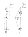
- the reference 1 designates an electric line monitored between two ends A and B distant by a length L. It is assumed that a fault (for example fault between one or more phases and the earth, or fault between phases) exists at point D at a distance d from point A.
- the line impedances upstream of point A and downstream of point B are designated by Z SA and Z SB .
- the fault location by the generator fault method is derived from the transition voltage diagram of the figure 2.
- Relations (1) and (2 ) he comes :
- each of the quantities ⁇ V A , ⁇ I A , ⁇ V B , ⁇ I B is a transition quantity, i.e. has a value equal to the difference between its value after fault and its value before fault .
- relation (3) is independent of the impedance of the fault.
- the terms ⁇ V A , ⁇ I A , ⁇ V B , ⁇ I B are complex numbers, and relation (3) can only be simplified into a formula between the modules of quantities if all the impedances of the network in which the line L is found have the same argument.
- the measured transition quantities ⁇ V A , ⁇ I A , ⁇ V B , ⁇ I B are chosen from quantities of a non-homopolar mode, for example the direct mode.
- the impedance Z L is then that corresponding to the chosen mode, this impedance being a known characteristic of line 1.
- the calculation of x requires have the results of the measurements taken at the two ends of the line at the same point. It will be assumed that the calculation is carried out at point A, which requires the transmission from B to A of the results of the measurements carried out at point B. This transmission can be carried out by radio.
- the method according to the invention is therefore particularly suitable for being used in combination with a line differential protection system for which there are links transmitting the magnitudes of currents between the ends of the line.
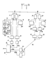
- FIG. 3 An implementation of the method according to the invention with use of the time values of the measured transition quantities is illustrated in FIG. 3.
- Measuring devices 11, 12 make it possible to have, in real time at point A, values of the quantities in the chosen mode, for example the direct voltage and current V A , I A. It will be noted that such devices making it possible to supply direct, inverse, polar phase, interphase or other quantities are known and do not require here a particular description.
- the signals V A and I A are copied by means of storage circuits 13, 14 whose state can be frozen at a desired time.
- the signals representative of V A and I A at the output of the circuits 13, 14 are applied to respective subtractors 15, 16 which also directly receive the output signals from the measuring devices.
- the states of circuits 13, 14 are frozen under the control of an SD signal supplied by a fault detection device (not shown).
- the circuits 13, 14 then deliver signals representative of the quantities V A , I A before fault and there are therefore, at the output of the subtractors 15, 16, the desired values of the transition quantities ⁇ V A and ⁇ I A.
- Each of the circuits 13, 14 thus has the function of memorizing the phase and the amplitude of a voltage or current signal as it existed before the fault and of delivering, after the appearance of the fault, an extrapolated signal representing the voltage or current signal as it would have existed in the absence of a fault.
- measurement devices 21, 22 supplying the values of the direct voltage and current V B , I B , storage circuits 23, 24 intended to reproduce the values of V B and I B before default, and of subtractors 25, 26 providing the transition quantities ⁇ V B , ⁇ I B.
- the measured values of the quantities ⁇ V B and ⁇ I B are applied to transmitters 31, 32 where they are modulated, possibly after coding, to be transmitted in real time to point A.
- the signals received at point A are demodulated and possibly decoded by receivers 33, 34.
- the transmission between point B and point A is carried out by a communication channel 30 using one channel for the transition current and another channel for the transition voltage.
- the values of the quantities ⁇ V A , ⁇ I A , ⁇ V B and ⁇ I B are applied to a calculation circuit 19 which develops the quantity x from the values of the transition quantities and the prerecorded value of the impedance Z L of the line in the chosen mode.
- Delay circuits 17, 18 are interposed between the subtractors 15, 16 and the circuit 19 to compensate for the delay in transmitting the values of the quantities ⁇ V B , ⁇ I B.
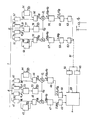
- measuring devices 41, 42 supplying the values of V A and I A
- memory circuits 43, 44 receiving V A and I A and frozen in l appearance of a fault
- subtractors 45, 46 supplying the instantaneous values of ⁇ V A and ⁇ I A after appearance of the fault.
- the value of ⁇ I A is multiplied by Z L and the values of ⁇ V A and Z L ⁇ I A are each multiplied by the same reference voltage V R.
- the products obtained are integrated by means of respective integrators 47, 48 over a period T from the appearance of the fault, that is to say from the reception of the signal SD.
- the values obtained for the stored in respective memories 49, 50 are provided for the stored in respective memories 49, 50.
- measuring devices 51, 52 supplying the values of V B , I B , storage circuits 53, 54 receiving V B and I B and frozen at the appearance of a default, subtractors 55, 56 providing the instantaneous values of ⁇ V B and ⁇ I B , integrators 57, 58 providing the values of the integrals.
- the scalar quantities developed at point B are applied to transmission circuits 62, 63 where they are modulated, possibly after coding, and transmitted by means of a link 61 to point A where they are demodulated and possibly decoded by receivers 64, 65.
- the calculation of x is carried out offline by applying the equation:
- This calculation is carried out by means of a calculation circuit 69 receiving the various scalar quantities.
- scalar quantities makes it possible to avoid a transmission in real time from the end B to the end A, with compensation for the transmission delay, since the transmission and the calculation can be carried out deferred. Since this frees you from synchronization problems, there is no point in fully allocating a communication channel for the transmission of the signal concerned. Also, the transmission of scalar quantities from point B to point A can advantageously be carried out by means of a switched or time-shared communication channel.
- the reference voltage V R must be the same at A and at B.
- the operating voltage existing before fault and stored can be used.
- the quantities V LA and I LA are supplied by measuring devices 70, 71 whose outputs are combined by means of a circuit 72 supplying
- circuit 72 The output of circuit 72 is applied to a storage circuit 73 which delivers the voltage V R , the storage circuit 73 having for example a structure analogous to that of circuits 13, 14.
- the quantities V LB and I LB are supplied by measuring devices 75, 76, then are combined by a circuit 77 to provide a quantity which is applied to a memory circuit 78.
- V R The choice of the reference voltage V R as defined above is not limiting, other quantities that can be used insofar as they make it possible to have identical references at the two ends of the line.
- V R the voltage defined above
- V ⁇ R obtained by phase shift of V R by 90 °.
- the scalar quantities developed from the measurements of ⁇ V A , ⁇ I A , ⁇ V B and ⁇ I B will then for example be of the form
Landscapes
- Physics & Mathematics (AREA)
- General Physics & Mathematics (AREA)
- Locating Faults (AREA)
Applications Claiming Priority (2)
| Application Number | Priority Date | Filing Date | Title |
|---|---|---|---|
| FR8519433 | 1985-12-30 | ||
| FR8519433A FR2592492B1 (fr) | 1985-12-30 | 1985-12-30 | Procede de localisation d'un defaut sur une ligne electrique |
Publications (2)
| Publication Number | Publication Date |
|---|---|
| EP0230801A1 true EP0230801A1 (de) | 1987-08-05 |
| EP0230801B1 EP0230801B1 (de) | 1992-07-15 |
Family
ID=9326320
Family Applications (1)
| Application Number | Title | Priority Date | Filing Date |
|---|---|---|---|
| EP19860402623 Expired - Lifetime EP0230801B1 (de) | 1985-12-30 | 1986-11-26 | Verfahren zur Fehlerortung auf einer elektrischen Leitung |
Country Status (3)
| Country | Link |
|---|---|
| EP (1) | EP0230801B1 (de) |
| DE (1) | DE3686040T2 (de) |
| FR (1) | FR2592492B1 (de) |
Cited By (2)
| Publication number | Priority date | Publication date | Assignee | Title |
|---|---|---|---|---|
| EP0358488A3 (de) * | 1988-09-09 | 1991-03-20 | Gec Alsthom Limited | Anordnung und Verfahren zum Lokalisieren eines Fehlers in einer Transmissionsleitung |
| FR2727762A1 (fr) * | 1994-12-05 | 1996-06-07 | Excem | Dispositif pour la localisation de defauts sur les liaisons sous-marines de telecommunications |
Families Citing this family (1)
| Publication number | Priority date | Publication date | Assignee | Title |
|---|---|---|---|---|
| CN112162175B (zh) * | 2020-09-18 | 2022-12-09 | 武汉三相电力科技有限公司 | 具有锚段的接触网故障点的校正方法、装置及系统 |
Citations (3)
| Publication number | Priority date | Publication date | Assignee | Title |
|---|---|---|---|---|
| US3462681A (en) * | 1967-08-23 | 1969-08-19 | American Telephone & Telegraph | Fault locating system utilizing narrow bandwidth channel to transmit fault surge arrival times to a master timing location |
| DE2112136A1 (de) * | 1971-03-10 | 1972-09-14 | Siemens Ag | Schaltungsanordnung zum Messen der Fehlerstellenentfernung bei Leitungskurzschluessen |
| FR2538122A1 (fr) * | 1982-12-16 | 1984-06-22 | Enertec | Perfectionnement aux procedes et dispositifs de determination d'un parametre associe a une ligne electrique en defaut |
-
1985
- 1985-12-30 FR FR8519433A patent/FR2592492B1/fr not_active Expired
-
1986
- 1986-11-26 DE DE19863686040 patent/DE3686040T2/de not_active Expired - Fee Related
- 1986-11-26 EP EP19860402623 patent/EP0230801B1/de not_active Expired - Lifetime
Patent Citations (3)
| Publication number | Priority date | Publication date | Assignee | Title |
|---|---|---|---|---|
| US3462681A (en) * | 1967-08-23 | 1969-08-19 | American Telephone & Telegraph | Fault locating system utilizing narrow bandwidth channel to transmit fault surge arrival times to a master timing location |
| DE2112136A1 (de) * | 1971-03-10 | 1972-09-14 | Siemens Ag | Schaltungsanordnung zum Messen der Fehlerstellenentfernung bei Leitungskurzschluessen |
| FR2538122A1 (fr) * | 1982-12-16 | 1984-06-22 | Enertec | Perfectionnement aux procedes et dispositifs de determination d'un parametre associe a une ligne electrique en defaut |
Cited By (6)
| Publication number | Priority date | Publication date | Assignee | Title |
|---|---|---|---|---|
| EP0358488A3 (de) * | 1988-09-09 | 1991-03-20 | Gec Alsthom Limited | Anordnung und Verfahren zum Lokalisieren eines Fehlers in einer Transmissionsleitung |
| US5072403A (en) * | 1988-09-09 | 1991-12-10 | Gec Alsthom Limited | Equipment for and methods of locating the position of a fault on a power transmission line |
| AU618843B2 (en) * | 1988-09-09 | 1992-01-09 | Areva T&D Uk Ltd | Equipment for and methods of locating the position of a fault on a power transmission line |
| FR2727762A1 (fr) * | 1994-12-05 | 1996-06-07 | Excem | Dispositif pour la localisation de defauts sur les liaisons sous-marines de telecommunications |
| WO1996018111A1 (fr) * | 1994-12-05 | 1996-06-13 | Excem | Dispositif pour la localisation de defauts sur les liaisons sous-marines de telecommunications |
| US5883517A (en) * | 1994-12-05 | 1999-03-16 | Excem | Device for locating defects in underwater telecommunication links |
Also Published As
| Publication number | Publication date |
|---|---|
| DE3686040D1 (de) | 1992-08-20 |
| EP0230801B1 (de) | 1992-07-15 |
| FR2592492B1 (fr) | 1988-04-01 |
| DE3686040T2 (de) | 1993-01-21 |
| FR2592492A1 (fr) | 1987-07-03 |
Similar Documents
| Publication | Publication Date | Title |
|---|---|---|
| EP2006694B1 (de) | Vorrichtung zur lokalisierten Kontrolle und Messung der Isolierung von Stromnetzen mit isoliertem Nullleiter | |
| CA1201504A (fr) | Procede et dispositif de teletransmission de signaux et application a la detection et/ou mesure de la teneur en gaz combustible d'une atmosphere | |
| FR2819053A1 (fr) | Systemes et procedes pour la localisation de defauts sur une ligne de transmission a charge branchee unique | |
| EP0518785A1 (de) | Anordnung zur Überwachung und Messung der Isolierung für elektrische Netze mit isoliertem Nulleiter | |
| EP0187067B1 (de) | Umschaltungssystem für ein digitales Übertragungsnetz | |
| CA1212416A (fr) | Telephaseur pour l'identification des phases a distance de lignes de transport et/ou d'arteres dans un reseau electrique | |
| EP0053069B1 (de) | Verfahren zur Richtungserkennung einer Störung in einem elektrischen Netz | |
| EP0230801B1 (de) | Verfahren zur Fehlerortung auf einer elektrischen Leitung | |
| EP0834983A2 (de) | Anordnung zur Strommessung in einem Wechselrichter | |
| EP0229547B1 (de) | Verfahren und Gerät zur Erkennung eines fehlerhaften Leiters in einer Mehrfachleitung | |
| CA1106916A (fr) | Appareil et procede pour regulariser le facteur de puissance d'une ligne de reseau de distribution electrique | |
| EP0403330A1 (de) | Eingangsschaltung für Elektrizitätszähler | |
| EP2045610B1 (de) | Fehlerlokalisierung in einem öffentlichen Mittelspannungsverteilernetz | |
| FR2727762A1 (fr) | Dispositif pour la localisation de defauts sur les liaisons sous-marines de telecommunications | |
| FR2491283A1 (fr) | Transformateurs a circuit imprime | |
| EP0537066B1 (de) | Verfahren zur selektiven Detektion von Widerstandsdefekten in Stromverteilungsnetzwerken | |
| EP0276181B1 (de) | Verfahren und Einrichtung zur Untersuchung von fehlerbehafteten Leitern einer elektrischen Leitung | |
| EP0628828B1 (de) | Mess- und Zählvorrichtung für elektrische Energie | |
| FR3012617A1 (fr) | Methode de localisation de defauts electriques au sein d'un reseau de lignes de transmission et systeme associe | |
| EP4343344B1 (de) | Verfahren zur fehlerortung in einem elektrischen versorgungsnetz | |
| EP3798648B1 (de) | Verfahren zur bestimmung der position einer fehlervorstufe in einem in betrieb befindlichen hochspannungskabel | |
| EP4089422B1 (de) | Vorrichtung und verfahren zur schätzung der isolationsimpedanz eines tt- oder tn-netzes | |
| FR2554929A1 (fr) | Procede pour la determination rapide de la valeur d'une puissance alternative ou d'une energie alternative consommee | |
| EP2028499B1 (de) | Kontrolle der Isolierung einer Einheit von Stromnetzen mit isoliertem Nullleiter | |
| FR3139249A1 (fr) | Procédé et dispositif de compensation d’un déséquilibre capacitif d’une liaison électrique |
Legal Events
| Date | Code | Title | Description |
|---|---|---|---|
| PUAI | Public reference made under article 153(3) epc to a published international application that has entered the european phase |
Free format text: ORIGINAL CODE: 0009012 |
|
| AK | Designated contracting states |
Kind code of ref document: A1 Designated state(s): CH DE FR GB LI SE |
|
| 17P | Request for examination filed |
Effective date: 19870904 |
|
| RAP1 | Party data changed (applicant data changed or rights of an application transferred) |
Owner name: SCHLUMBERGER INDUSTRIES |
|
| 17Q | First examination report despatched |
Effective date: 19900212 |
|
| GRAA | (expected) grant |
Free format text: ORIGINAL CODE: 0009210 |
|
| AK | Designated contracting states |
Kind code of ref document: B1 Designated state(s): CH DE FR GB LI SE |
|
| REF | Corresponds to: |
Ref document number: 3686040 Country of ref document: DE Date of ref document: 19920820 |
|
| GBT | Gb: translation of ep patent filed (gb section 77(6)(a)/1977) | ||
| RAP2 | Party data changed (patent owner data changed or rights of a patent transferred) |
Owner name: PSC PROTECTIONS ET SYSTEMES DE CONTROLE |
|
| REG | Reference to a national code |
Ref country code: CH Ref legal event code: PUE Owner name: PSC PROTECTIONS ET SYSTEMES DE CONTROLE |
|
| RAP2 | Party data changed (patent owner data changed or rights of a patent transferred) |
Owner name: GEC ALSTHOM PROTECTION & CONTROLE |
|
| REG | Reference to a national code |
Ref country code: CH Ref legal event code: PUE Owner name: GEC ALSTHOM PROTECTION ET CONTROLE |
|
| PLBE | No opposition filed within time limit |
Free format text: ORIGINAL CODE: 0009261 |
|
| STAA | Information on the status of an ep patent application or granted ep patent |
Free format text: STATUS: NO OPPOSITION FILED WITHIN TIME LIMIT |
|
| 26N | No opposition filed | ||
| EAL | Se: european patent in force in sweden |
Ref document number: 86402623.2 |
|
| REG | Reference to a national code |
Ref country code: GB Ref legal event code: IF02 |
|
| PGFP | Annual fee paid to national office [announced via postgrant information from national office to epo] |
Ref country code: GB Payment date: 20031029 Year of fee payment: 18 |
|
| PGFP | Annual fee paid to national office [announced via postgrant information from national office to epo] |
Ref country code: CH Payment date: 20031030 Year of fee payment: 18 |
|
| PGFP | Annual fee paid to national office [announced via postgrant information from national office to epo] |
Ref country code: SE Payment date: 20031103 Year of fee payment: 18 Ref country code: DE Payment date: 20031103 Year of fee payment: 18 |
|
| PGFP | Annual fee paid to national office [announced via postgrant information from national office to epo] |
Ref country code: FR Payment date: 20031107 Year of fee payment: 18 |
|
| PG25 | Lapsed in a contracting state [announced via postgrant information from national office to epo] |
Ref country code: GB Free format text: LAPSE BECAUSE OF NON-PAYMENT OF DUE FEES Effective date: 20041126 |
|
| PG25 | Lapsed in a contracting state [announced via postgrant information from national office to epo] |
Ref country code: SE Free format text: LAPSE BECAUSE OF NON-PAYMENT OF DUE FEES Effective date: 20041127 |
|
| PG25 | Lapsed in a contracting state [announced via postgrant information from national office to epo] |
Ref country code: LI Free format text: LAPSE BECAUSE OF NON-PAYMENT OF DUE FEES Effective date: 20041130 Ref country code: CH Free format text: LAPSE BECAUSE OF NON-PAYMENT OF DUE FEES Effective date: 20041130 |
|
| PG25 | Lapsed in a contracting state [announced via postgrant information from national office to epo] |
Ref country code: DE Free format text: LAPSE BECAUSE OF NON-PAYMENT OF DUE FEES Effective date: 20050601 |
|
| EUG | Se: european patent has lapsed | ||
| GBPC | Gb: european patent ceased through non-payment of renewal fee |
Effective date: 20041126 |
|
| REG | Reference to a national code |
Ref country code: CH Ref legal event code: PL |
|
| PG25 | Lapsed in a contracting state [announced via postgrant information from national office to epo] |
Ref country code: FR Free format text: LAPSE BECAUSE OF NON-PAYMENT OF DUE FEES Effective date: 20050729 |
|
| REG | Reference to a national code |
Ref country code: FR Ref legal event code: ST |