EP0230823A1 - Bremskraftverstärker mit doppelter Reaktionsscheibe - Google Patents
Bremskraftverstärker mit doppelter Reaktionsscheibe Download PDFInfo
- Publication number
- EP0230823A1 EP0230823A1 EP86402843A EP86402843A EP0230823A1 EP 0230823 A1 EP0230823 A1 EP 0230823A1 EP 86402843 A EP86402843 A EP 86402843A EP 86402843 A EP86402843 A EP 86402843A EP 0230823 A1 EP0230823 A1 EP 0230823A1
- Authority
- EP
- European Patent Office
- Prior art keywords
- disc
- intermediate element
- booster according
- cooperating
- booster
- Prior art date
- Legal status (The legal status is an assumption and is not a legal conclusion. Google has not performed a legal analysis and makes no representation as to the accuracy of the status listed.)
- Granted
Links
Images
Classifications
-
- B—PERFORMING OPERATIONS; TRANSPORTING
- B60—VEHICLES IN GENERAL
- B60T—VEHICLE BRAKE CONTROL SYSTEMS OR PARTS THEREOF; BRAKE CONTROL SYSTEMS OR PARTS THEREOF, IN GENERAL; ARRANGEMENT OF BRAKING ELEMENTS ON VEHICLES IN GENERAL; PORTABLE DEVICES FOR PREVENTING UNWANTED MOVEMENT OF VEHICLES; VEHICLE MODIFICATIONS TO FACILITATE COOLING OF BRAKES
- B60T13/00—Transmitting braking action from initiating means to ultimate brake actuator with power assistance or drive; Brake systems incorporating such transmitting means, e.g. air-pressure brake systems
- B60T13/10—Transmitting braking action from initiating means to ultimate brake actuator with power assistance or drive; Brake systems incorporating such transmitting means, e.g. air-pressure brake systems with fluid assistance, drive, or release
- B60T13/24—Transmitting braking action from initiating means to ultimate brake actuator with power assistance or drive; Brake systems incorporating such transmitting means, e.g. air-pressure brake systems with fluid assistance, drive, or release the fluid being gaseous
- B60T13/46—Vacuum systems
- B60T13/52—Vacuum systems indirect, i.e. vacuum booster units
- B60T13/573—Vacuum systems indirect, i.e. vacuum booster units characterised by reaction devices
- B60T13/575—Vacuum systems indirect, i.e. vacuum booster units characterised by reaction devices using resilient discs or pads
Definitions
- the present invention relates to braking assistance servomotors of the type comprising: an assistance piston coupled to an output rod, intended to be connected to a brake master cylinder piston, and containing an actuated distribution valve means by a valve plunger connected to an input rod of the booster, intended to be connected to a vehicle brake pedal, and a reaction disc, confined peripherally, interposed between the rear end of the output rod, on the one hand, and the front end of the plunger and a peripheral annular central shoulder of the assistance piston, on the other hand.
- a brake booster of this type is described in document US-A-3 110 031.
- the reaction disc typically made of elastomeric material, is interposed directly between the rear end, generally enlarged, of the outlet rod and the front end, generally of reduced diameter, of the plunger, the reaction force exerted on the inlet rod, via the valve plunger, during the implementation of the servomotor for the actuation of a master cylinder associated with the latter, being determined by the respective cross sections of the rear end of the rod (and of the reaction disc) and of the front end of the valve plunger, which are located generally in a ratio of about 2.5.
- the object of the present invention is to propose improvements to booster motors of this type allowing increased sensitivity during the use of the booster and consequently authorizing a significant reduction in the lever ratio of the brake actuation pedal and , starting from the course of the latter, by means of a simple, robust and reliable arrangement, entailing only very low additional manufacturing costs and mounting, and adaptable to any type of existing servomotor including a reaction disc.
- the booster comprises a second reaction disc, confined peripherally, cooperating with the rear end of the outlet rod, and a stepped intermediate element interposed between the two reaction discs and cooperating with these.
- the intermediate element comprises a front portion of reduced diameter extending to slide in a central bore of an annular spacer element forming a cooperating peripheral shoulder, with the front end of the reduced diameter portion of the intermediate element, with the rear face of the second disc.
- the sensitivity ratio of the servomotor becomes the product of the relationships between the cross sections of the second disc and of the front end of the reduced diameter portion of the intermediate element, on the one hand, and of the first disc. and from the front end of the valve plunger, on the other hand.
- front and rear relate to the general orientation of a vehicle in which the booster is installed, “front” thus corresponding to the left of the Single figure and “back” to the right of the Figure.
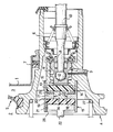
- a pneumatic booster for assisting braking comprising a housing, a portion of the rear shell 1 of which is seen, internally divided into a front chamber, or vacuum chamber, 2 and a rear chamber, or working chamber 3, by an assistance piston comprising a part of central hub 4 and a peripheral diaphragm means 5.
- the central hub part 4 comprises a rear tubular part 6 of reduced diameter sliding in a rear chimney 7 of the housing and enclosing a distribution valve means, generally designated by the reference 8, actuated by a valve plunger 9 coupled to the end of an input rod 10 connected, at its other end, to a vehicle brake pedal (not shown).
- valve plunger 9 slides in a central stepped bore 11 of the hub part 4 and has a front end portion 12 of reduced diameter d1 intended to cooperate, during the implementation of the booster, with a first reaction disc 13, typically made of elastomeric material, carried in the hub part 4 and of diameter greater than the diameter d1, the rear annular peripheral portion of the first disc 13 bearing against an annular central shoulder 14 of the part of the hub 4 surrounding, coaxially the end front 12 of valve plunger 9.
- a first reaction disc 13 typically made of elastomeric material
- the first disc 13 is confined peripherally in a tubular cage 15 received in an annular groove 16 of the central hub part 4 and comprising an annular spacer element extending radially inwards 17, formed advantageously of a single metal part with the cage 15, and defining a central bore 18 of diameter d2 advantageously less than the diameter d1.
- a second reaction disc 19 also made of elastomeric material, the annular peripheral portion of the rear face of which is in contact against the front annular face 20 of the annular spacer element 17, and whose the front face bears against an enlarged end portion 21, of same diameter as the second disc 19, of an output rod 22 of the booster, typically intended to be coupled to a primary piston of a brake master cylinder (not shown).
- an intermediate element generally designated by the reference 23, comprising a front portion of reduced diameter 24 slidably mounted in the bore 18 of the element annular spacer 17 and whose front end is intended to cooperate with the central portion of the rear face of the second disc 19, and a rear part 25 of enlarged diameter substantially equal to that of the first disc 13 and whose rear face is intended to cooperate with the front face of the first disc 13.
- the cage 15 advantageously defines, on either side of the spacer element 17, a bore of constant diameter 26 in which the rear end 21 of the outlet rod 22, the two advantageously identical discs 29 and 13, and the rear part 25 of the intermediate element 23.
- the operation of the booster according to the invention is identical in all respects to that of conventional servomotors except that, during the implementation of the servomotor, when the valve plunger 9 is advanced forward to actuate the means distribution valve 8, and that its front end 12 thus bears against the central part of the first disc 13, the reaction force transmitted from the outlet rod 22 to the valve plunger 9 is, as mentioned above, the product of the ratio of the sections of the second disc 19 and of the reduced diameter front portion 24 of the intermediate element 23, on the one hand, and of the ratio of the sections of the first disc 13 and of the portion of the front end 12 of the plunger valve 9, on the other hand, thereby considerably increasing the sensitivity ratio of the actuator without affecting the operation, moreover precisely adjusted, of the valve means 8 and of the associated valve plunger 9.
- the ratio of the cross sections of the prem ier disc 13 and the front portion of the reduced diameter 12 of the valve plunger 9 is typically about 2.5, the ratio of the cross sections of the second disc 19 and the front portion of reduced diameter 24 of the intermediate element 23 being greater than 2.5 and less than 5, typically on the order of 4.5 to provide an overall ratio of approximately 11.
Landscapes
- Engineering & Computer Science (AREA)
- Transportation (AREA)
- Mechanical Engineering (AREA)
- Braking Systems And Boosters (AREA)
Applications Claiming Priority (2)
| Application Number | Priority Date | Filing Date | Title |
|---|---|---|---|
| FR8600165A FR2592620B1 (fr) | 1986-01-08 | 1986-01-08 | Servomoteur d'assistance au freinage a double disque de reaction. |
| FR8600165 | 1986-01-08 |
Publications (2)
| Publication Number | Publication Date |
|---|---|
| EP0230823A1 true EP0230823A1 (de) | 1987-08-05 |
| EP0230823B1 EP0230823B1 (de) | 1989-11-15 |
Family
ID=9330897
Family Applications (1)
| Application Number | Title | Priority Date | Filing Date |
|---|---|---|---|
| EP86402843A Expired EP0230823B1 (de) | 1986-01-08 | 1986-12-17 | Bremskraftverstärker mit doppelter Reaktionsscheibe |
Country Status (5)
| Country | Link |
|---|---|
| US (1) | US4719842A (de) |
| EP (1) | EP0230823B1 (de) |
| DE (1) | DE3666932D1 (de) |
| ES (1) | ES2011620B3 (de) |
| FR (1) | FR2592620B1 (de) |
Families Citing this family (12)
| Publication number | Priority date | Publication date | Assignee | Title |
|---|---|---|---|---|
| JP2509719Y2 (ja) * | 1988-12-26 | 1996-09-04 | 自動車機器 株式会社 | 負圧倍力装置 |
| US5054370A (en) * | 1991-02-13 | 1991-10-08 | General Motors Corporation | Vacuum booster with dual durometer reaction disc |
| FR2691691B1 (fr) * | 1992-05-26 | 1996-08-09 | Bendix Europ Services Tech | Servomoteur pneumatique. |
| JP3575627B2 (ja) * | 1994-06-30 | 2004-10-13 | 株式会社ボッシュオートモーティブシステム | 倍力装置の弁機構 |
| JPH10129459A (ja) * | 1996-10-25 | 1998-05-19 | Jidosha Kiki Co Ltd | 倍力装置 |
| US5893316A (en) * | 1996-12-27 | 1999-04-13 | Jidosha Kiki Co., Ltd. | Brake booster |
| JPH1159399A (ja) * | 1997-08-15 | 1999-03-02 | Jidosha Kiki Co Ltd | ブレーキ倍力装置 |
| JP2000079877A (ja) * | 1998-06-29 | 2000-03-21 | Aisin Seiki Co Ltd | 負圧式倍力装置 |
| FR2816569B1 (fr) * | 2000-11-15 | 2003-02-14 | Bosch Sist De Frenado Sl | Dispositif a disque de reaction, son procede de realisation et servomoteur d'assistance comportant un tel dispositif |
| FR2820388B1 (fr) * | 2001-02-07 | 2004-05-28 | Bosch Sist De Frenado Sl | Dispositif de reaction pour servomoteur pneumatique d'assistance au freinage et servomoteur pneumatique d'assistance au freinage comportant un tel dispositif |
| JP4091435B2 (ja) * | 2001-02-15 | 2008-05-28 | コンティネンタル・テーベス・アクチエンゲゼルシヤフト・ウント・コンパニー・オッフェネ・ハンデルスゲゼルシヤフト | ブレーキ倍力装置用ブレーキ力伝達装置 |
| JP2003089353A (ja) * | 2001-09-18 | 2003-03-25 | Bosch Automotive Systems Corp | 倍力装置 |
Citations (4)
| Publication number | Priority date | Publication date | Assignee | Title |
|---|---|---|---|---|
| US3035551A (en) * | 1960-11-25 | 1962-05-22 | Gen Motors Corp | Brake booster unit |
| US3110031A (en) | 1959-08-21 | 1963-11-05 | Bendix Corp | Reaction means for servomotors |
| US3146679A (en) * | 1963-11-04 | 1964-09-01 | Kelsey Hayes Co | Fluid pressure motor mechanism |
| EP0014146A1 (de) * | 1979-01-29 | 1980-08-06 | The Bendix Corporation | Steuerventil für pneumatisch bediente Servomotoren |
Family Cites Families (1)
| Publication number | Priority date | Publication date | Assignee | Title |
|---|---|---|---|---|
| US4587885A (en) * | 1983-09-09 | 1986-05-13 | Itt Industries, Inc. | Vacuum-operated brake power booster |
-
1986
- 1986-01-08 FR FR8600165A patent/FR2592620B1/fr not_active Expired
- 1986-12-17 DE DE8686402843T patent/DE3666932D1/de not_active Expired
- 1986-12-17 EP EP86402843A patent/EP0230823B1/de not_active Expired
- 1986-12-17 ES ES86402843T patent/ES2011620B3/es not_active Expired - Lifetime
-
1987
- 1987-01-06 US US07/000,803 patent/US4719842A/en not_active Expired - Fee Related
Patent Citations (4)
| Publication number | Priority date | Publication date | Assignee | Title |
|---|---|---|---|---|
| US3110031A (en) | 1959-08-21 | 1963-11-05 | Bendix Corp | Reaction means for servomotors |
| US3035551A (en) * | 1960-11-25 | 1962-05-22 | Gen Motors Corp | Brake booster unit |
| US3146679A (en) * | 1963-11-04 | 1964-09-01 | Kelsey Hayes Co | Fluid pressure motor mechanism |
| EP0014146A1 (de) * | 1979-01-29 | 1980-08-06 | The Bendix Corporation | Steuerventil für pneumatisch bediente Servomotoren |
Also Published As
| Publication number | Publication date |
|---|---|
| US4719842A (en) | 1988-01-19 |
| DE3666932D1 (en) | 1989-12-21 |
| EP0230823B1 (de) | 1989-11-15 |
| FR2592620A1 (fr) | 1987-07-10 |
| ES2011620B3 (es) | 1990-02-01 |
| FR2592620B1 (fr) | 1988-04-15 |
Similar Documents
| Publication | Publication Date | Title |
|---|---|---|
| EP0075505B1 (de) | Verfahren und Vorrichtung zur Regelung des Totweges von Hauptbremszylindern und durch die Anwendung dieses Verfahrens eingestellte Bremsbetätigungseinheit | |
| EP0230823B1 (de) | Bremskraftverstärker mit doppelter Reaktionsscheibe | |
| EP0501843B1 (de) | Bremskraftverstärker mit einstellbarem Schwellenwert und Verfahren zum Regeln des Schwellenwertes | |
| EP0939713B1 (de) | Hilfskraftbremsvorrichtung mit variablem verstärkerverhältnis und verringerter hysterese | |
| EP0340059B1 (de) | Bremskraftverstärker mit einstellbarem Schwellenwert | |
| EP0402183B1 (de) | Verfahren zum Regeln des Wertes eines Sprungs an einem Bremskraftverstärker | |
| EP0153888B1 (de) | Bremsverstärker | |
| EP1565367B1 (de) | Verfahren zur einstellung eines bremssystems | |
| FR2724356A1 (fr) | Servomoteur pneumatique d'assistance au freinage | |
| EP0915791B1 (de) | Bremskraftverstärker mit hydraulischer reaktion und mit grösserer sicherheit | |
| FR2666552A1 (fr) | Procede de reglage de la valeur du saut d'un servomoteur pneumatique d'assistance au freinage et servomoteur pour la mise en óoeuvre de ce procede. | |
| EP0218490B1 (de) | Unterdruckbremskraftverstärker | |
| FR2663598A1 (fr) | Servomoteur d'assistance a depression. | |
| EP1057704B1 (de) | Verbesserter Bremsverstärker | |
| EP0730538B1 (de) | Bremsvorrichtung mit maskiertem hub und gleichbleibender verstärkung | |
| EP0877689A1 (de) | Bremskraftverstärker mit verbessertem ventil | |
| EP0220987A1 (de) | Unterdruckbremskraftverstärker und Verfahren zu seiner Regelung | |
| EP1741608B1 (de) | Bremskraftverstärker mit zwei Verstärkungsfaktoren | |
| EP0449703B1 (de) | Verfahren zum Regeln des Schwellenwertes an einem Bremskraftverstärker | |
| EP0230169B1 (de) | Unterdruckbremskraftverstärker | |
| EP0368701B1 (de) | Hydraulische Servobremsanlage und Bremskraftverstärker und Regelventil für eine solche Anlage | |
| WO1998022321A1 (fr) | Systeme de feinage assiste a reaction hydraulique amelioree | |
| EP1431152A1 (de) | Pneumatischer Bremskraftverstärker, insbesondere für Kraftfahrzeuge | |
| EP0406033A1 (de) | Bremskraftverstärker | |
| FR2864504A1 (fr) | Servomoteur de freinage a saut reglable et procede de reglage dudit servomoteur. |
Legal Events
| Date | Code | Title | Description |
|---|---|---|---|
| PUAI | Public reference made under article 153(3) epc to a published international application that has entered the european phase |
Free format text: ORIGINAL CODE: 0009012 |
|
| 17P | Request for examination filed |
Effective date: 19861226 |
|
| AK | Designated contracting states |
Kind code of ref document: A1 Designated state(s): DE ES GB IT |
|
| 17Q | First examination report despatched |
Effective date: 19881012 |
|
| GRAA | (expected) grant |
Free format text: ORIGINAL CODE: 0009210 |
|
| AK | Designated contracting states |
Kind code of ref document: B1 Designated state(s): DE ES GB IT |
|
| ITF | It: translation for a ep patent filed | ||
| GBT | Gb: translation of ep patent filed (gb section 77(6)(a)/1977) | ||
| REF | Corresponds to: |
Ref document number: 3666932 Country of ref document: DE Date of ref document: 19891221 |
|
| PLBE | No opposition filed within time limit |
Free format text: ORIGINAL CODE: 0009261 |
|
| STAA | Information on the status of an ep patent application or granted ep patent |
Free format text: STATUS: NO OPPOSITION FILED WITHIN TIME LIMIT |
|
| 26N | No opposition filed | ||
| ITTA | It: last paid annual fee | ||
| PGFP | Annual fee paid to national office [announced via postgrant information from national office to epo] |
Ref country code: GB Payment date: 19961209 Year of fee payment: 11 |
|
| PGFP | Annual fee paid to national office [announced via postgrant information from national office to epo] |
Ref country code: DE Payment date: 19961223 Year of fee payment: 11 |
|
| PGFP | Annual fee paid to national office [announced via postgrant information from national office to epo] |
Ref country code: ES Payment date: 19961230 Year of fee payment: 11 |
|
| PG25 | Lapsed in a contracting state [announced via postgrant information from national office to epo] |
Ref country code: GB Free format text: LAPSE BECAUSE OF NON-PAYMENT OF DUE FEES Effective date: 19971217 |
|
| PG25 | Lapsed in a contracting state [announced via postgrant information from national office to epo] |
Ref country code: ES Free format text: LAPSE BECAUSE OF THE APPLICANT RENOUNCES Effective date: 19971218 |
|
| GBPC | Gb: european patent ceased through non-payment of renewal fee |
Effective date: 19971217 |
|
| PG25 | Lapsed in a contracting state [announced via postgrant information from national office to epo] |
Ref country code: DE Free format text: LAPSE BECAUSE OF NON-PAYMENT OF DUE FEES Effective date: 19980901 |
|
| REG | Reference to a national code |
Ref country code: ES Ref legal event code: FD2A Effective date: 20010402 |
|
| PG25 | Lapsed in a contracting state [announced via postgrant information from national office to epo] |
Ref country code: IT Free format text: LAPSE BECAUSE OF NON-PAYMENT OF DUE FEES Effective date: 20051217 |