EP0230854A1 - Durchsichtige Platte als Teil eines Raumes in einem architektonischen Bau - Google Patents
Durchsichtige Platte als Teil eines Raumes in einem architektonischen Bau Download PDFInfo
- Publication number
- EP0230854A1 EP0230854A1 EP86810048A EP86810048A EP0230854A1 EP 0230854 A1 EP0230854 A1 EP 0230854A1 EP 86810048 A EP86810048 A EP 86810048A EP 86810048 A EP86810048 A EP 86810048A EP 0230854 A1 EP0230854 A1 EP 0230854A1
- Authority
- EP
- European Patent Office
- Prior art keywords
- panel
- face
- facets
- rays
- radiation
- Prior art date
- Legal status (The legal status is an assumption and is not a legal conclusion. Google has not performed a legal analysis and makes no representation as to the accuracy of the status listed.)
- Withdrawn
Links
- 238000010276 construction Methods 0.000 title claims abstract description 21
- 230000005855 radiation Effects 0.000 claims abstract description 46
- 230000005540 biological transmission Effects 0.000 claims abstract description 14
- 239000012780 transparent material Substances 0.000 claims abstract description 13
- 230000009471 action Effects 0.000 claims description 23
- 238000009826 distribution Methods 0.000 claims description 19
- 239000000463 material Substances 0.000 claims description 13
- 239000007787 solid Substances 0.000 claims description 12
- 230000009349 indirect transmission Effects 0.000 claims description 10
- 230000009365 direct transmission Effects 0.000 claims description 7
- 230000000295 complement effect Effects 0.000 claims description 6
- 230000000694 effects Effects 0.000 abstract description 9
- 230000008901 benefit Effects 0.000 description 9
- 239000011521 glass Substances 0.000 description 4
- 238000000034 method Methods 0.000 description 4
- 238000004378 air conditioning Methods 0.000 description 3
- 238000010438 heat treatment Methods 0.000 description 3
- 230000004048 modification Effects 0.000 description 3
- 238000012986 modification Methods 0.000 description 3
- 229920000297 Rayon Polymers 0.000 description 2
- 241000897276 Termes Species 0.000 description 2
- 230000015572 biosynthetic process Effects 0.000 description 2
- 239000000470 constituent Substances 0.000 description 2
- 238000013467 fragmentation Methods 0.000 description 2
- 238000006062 fragmentation reaction Methods 0.000 description 2
- 238000009434 installation Methods 0.000 description 2
- 230000003993 interaction Effects 0.000 description 2
- 230000035515 penetration Effects 0.000 description 2
- 239000002964 rayon Substances 0.000 description 2
- 101100536354 Drosophila melanogaster tant gene Proteins 0.000 description 1
- 230000002745 absorbent Effects 0.000 description 1
- 239000002250 absorbent Substances 0.000 description 1
- 239000011248 coating agent Substances 0.000 description 1
- 238000000576 coating method Methods 0.000 description 1
- 238000007796 conventional method Methods 0.000 description 1
- 238000011161 development Methods 0.000 description 1
- 238000010586 diagram Methods 0.000 description 1
- 238000005516 engineering process Methods 0.000 description 1
- 239000005329 float glass Substances 0.000 description 1
- 210000002837 heart atrium Anatomy 0.000 description 1
- 230000001939 inductive effect Effects 0.000 description 1
- 238000009413 insulation Methods 0.000 description 1
- 238000000465 moulding Methods 0.000 description 1
- 230000000422 nocturnal effect Effects 0.000 description 1
- 230000003287 optical effect Effects 0.000 description 1
- 238000005192 partition Methods 0.000 description 1
- 230000000149 penetrating effect Effects 0.000 description 1
- 229920003023 plastic Polymers 0.000 description 1
- 238000007639 printing Methods 0.000 description 1
- 230000008569 process Effects 0.000 description 1
- 230000000750 progressive effect Effects 0.000 description 1
- 238000011084 recovery Methods 0.000 description 1
- 230000003252 repetitive effect Effects 0.000 description 1
- 238000011160 research Methods 0.000 description 1
- 230000009897 systematic effect Effects 0.000 description 1
- 238000012546 transfer Methods 0.000 description 1
Images


Classifications
-
- F—MECHANICAL ENGINEERING; LIGHTING; HEATING; WEAPONS; BLASTING
- F21—LIGHTING
- F21S—NON-PORTABLE LIGHTING DEVICES; SYSTEMS THEREOF; VEHICLE LIGHTING DEVICES SPECIALLY ADAPTED FOR VEHICLE EXTERIORS
- F21S11/00—Non-electric lighting devices or systems using daylight
Definitions
- the present invention relates to a panel forming part of an enclosure in an architectural construction, having a face exposed in a determined orientation to light radiation, in particular solar, and consisting of one or more elements in one or more transparent materials, this or these elements each comprising at least one fragmented face formed of a set of facets inclined relative to the orientation of the panel, limiting prisms and exerting a selective action of total reflection or transmission on said radiation in function of the panel construction parameters: orientation of the element (s) and of the panel in space, number and thickness of the elements, number and position of the fragmented faces, refractive index of the material (s), angles of inclination, number, shape and dimension of the facets, thickness of the interstice (s) between the elements.
- the purpose of the present invention is to improve and bring a new development to the panels already known so as to allow the construction of enclosures which, studied according to the geographical location and the climate prevailing at the place where the panels must be installed, carry out a metering and an adjustment as meticulous as possible of the transmission of the luminous and calorific radiations striking the panel, taking into account the fact that these radiations vary in intensity and structure during the days and the seasons.
- the panel according to the invention which, by the selective action of the facets divides the solid angle of 180 ° encompassing all the directions of the beams of parallel rays striking the said exposed face, in distinct angular sectors in which the beams incidents are, for a first type of sector transmitted completely, for a second type of sector returned completely, and, if necessary, for a third type of sector partially transmitted and partially returned according to the angle and the point of incidence of the rays on the exposed side, allows by the choice of its construction parameters to determine the number, the relative positions, the limits of the angular sectors of each of these types and even, as regards certain sectors of the third type, the proportion of the transmitted and reflected beams.
- the angular distribution of the sectors thus determined is identical for all the regions of the panel.
- a large choice of possibilities as for the angular distribution of the sectors, is allowed by the diversity of structure of the prisms as for the number of facets, with the value of the angle with the tops of the prisms which they limit and other parameters of construction, and by the fact that each of the facets is determined so as to be able to be at the origin of several types of trajectories of direct radiation from the source inside the panel, each of them inducing at least three types of trajectories of these rays , one of the types of trajectories leading to a return of said rays to the source side, the type of trajectory leading to a direct transmission, i.e.
- a panel made entirely of transparent material can be configured so as to operate a very finely differentiated selection of the incident beams in three-dimensional space according to their angles of incidence.
- the choice of the values of the construction parameters is made as a function of a part of the set of positions in the said solid angle of 180 ° which the source occupies during a complete cycle, i.e. especially the portion of the solid angle of 180 ° that the sun travels during its daily and annual trajectory, on the other hand of all the sectors of the said three types that the panel determines in the whole of the solid angle of 180 ° and the orientations of this panel , so that it exerts a selective action determined on the incident radiation, according to the most important of these, direct radiation from the light source, and allows their return to the source side or their partial or total transmission at different times in a given sequence.
- the invention also relates to an enclosure in an architectural construction comprising one or more panels of the type specified above.
- It also relates to an element in one or more transparent materials comprising at least one fragmented face and intended to be incorporated into a panel as specified above.
- the constituent elements of the panel have a structure such that they can be produced in a completely rational manner, either by printing or molding according to conventional methods. either by finer processes using advanced technologies and using, for example, Float glass, the two kinds of methods can also be combined.
- the panels made up of the elements that are the subject of the invention can serve, for example, as a roof, as a cover, as opaque planes on the facade or on the roof, as a wall that is permeable to radiation, in particular greenhouses, covered malls or windows or bays glazed.
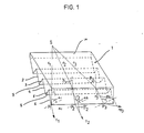
- the element 1 has a flat face 10 which will constitute the face of the panel exposed to incident radiation.
- the other side of the panel is a fragmented face consisting of a series of facets 2, 3,4,5,6, etc. of rectangular shapes joined along edges 7, 8, etc. which are parallel to each other and parallel to the face 10 of the element.
- all the facets 2,3,4,5,6 etc. are of the same shape and the same dimension, and that they are arranged symmetrically with respect to planes which are determined by perpendiculars to the face 10 and parallels to the edges 7, 8 etc.
- the different prisms formed by each pair of facets 2 and 3, 4 and 5, etc. are therefore symmetrical prisms, and for the understanding of the explanations which will follow it will be admitted that in a first variant the angle at the top of each prism, i.e. the dihedral angle between facets 2 and 3 or facets 4 and 5 is of the order of 106 °.
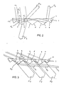
- a radius r2 from the same source also contained in a plane perpendicular to the face 10 and parallel to the edges 7, 8 etc. but doing with the perpendicular to the face 10 a beta angle 2, so that it undergoes refraction by crossing the face 10 and strikes the facet 6 at a point P2.
- the refracted ray r ⁇ 2 and the perpendicular to facet 6 at point P2 determine a plane pi 2 in which the transmitted ray t2 from point P2 of the refracted ray r ⁇ 2 will be contained.
- the plane pi 2 is different from the plane perpendicular to the face 10 and containing the source S.
- the angle of incidence alpha 2 of the refracted ray r ⁇ 2 with the perpendicular to the facet 6 at the point P2 is greater than the angle alpha 1. It will however be admitted that it still does not reach the critical angle, so that the radius t2 is indeed a transmitted radius.
- the facet 6 will have for the ray r ⁇ 3 an action of total reflection and will cause the sending of a reflected ray re3 which will end up emerging through the face 10, after a certain number of reflections in the element.
- the plane pi 3 determined by the rays r ⁇ 3 and re3 and in which is also contained the perpendicular to the facet 6 at the point P3 will also be a plane having an orientation different from that of the plane containing the rays r1, r2 and r3.
- Fig. 2 shows that, when the beta angle 4 increases, it reaches a value where the radii of the incident beam are no longer entirely transmitted, as was the case for rays r1, but where, after refraction and formation of rays r ⁇ 4, they fall on one of the facets 2,4,6, etc. for example facet 2, striking it at points P ⁇ 4 where their angle of incidence alpha 4 relative to the perpendicular to the facet is greater than the critical angle.
- this fact gives rise to two phenomena: on the one hand a part of the beam striking the facet 2 undergoes a first total reflection in the direction of the face 10, to be finally returned symmetrically to its direction of incidence after being reflected by facet 3, as indicated by the beam F4, and on the other hand part of the beam resulting from the first total reflection directly hits facet 3 and undergoes a new total reflection, so that it gives rise to the beam F ⁇ 4, which is then also returned towards the source side of the element 1.
- the fragmentation of the face opposite to the face 10 has the effect of a selection action of the third type, i.e. a partial return and a partial transmission of the beam, according to the precise point of incidence of each ray on the face 10.
- Fig. 3 shows a phenomenon of indirect transmission which appears for certain values of the inclination of the facets, for example for angles less than 116 ° to the vertices of symmetrical prisms when the refractive index of the transparent material is 1.5.
- the angle at the top is 106 °.
- each of these beams must, after having penetrated through the face 10 and having followed a more or less long trajectory inside this element, strike either a facet or the face 10, at an angle less than the critical angle.
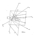
- Figs. 4 and 5 show how the invention takes advantage of these critical cones and the limits which correspond to them.
- Fig. 4 shows in perspective cut three striking rays, from the interior of the element, the face or a facet, F1, at point P.
- the radius r ⁇ 6, striking F at an angle of incidence less than the critical angle is transmitted with refraction by F at t6.
- the ray r ⁇ 7, striking F at an angle of incidence greater than the critical angle is reflected by F in the form of the reflected ray re7.
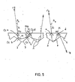
- Fig. 5 shows an element of the same index and the same configuration as FIGS. 1, 2 and 3. She shows in section the critical cones Cca, Ccb, Ccc, Ccd respectively surrounding the normals N of face 10, facet 2, facet 3 and again of face 10. It also shows the projection on the perpendicular plane at the edges, of two possible paths A and B for two rays r8 and r ⁇ 8 belonging to the same beam. These trajectories are located outside of said reference planes and are identical from the source to the point of reflection on the face 10 Pd.
- the component of its angle of refraction in the plane perpendicular to the element and parallel to the edges is less than 42 °, but sufficiently close to this figure so that the radius r8 which has become re8 after having been successively reflected by facet 2 and facet 3, reaches face 10 at point Pd from the outside of the cone Ccd, i.e. making an angle of more than 42 ° with the normal to this face.
- the component of the trajectory in the other reference plane i.e. the plane perpendicular to the edges is greater than at the point Pa.
- Fig. 6 shows such a graph where the x axis represents the incidences of 0 ° and 180 ° azimuths contained in the reference plane perpendicular to the face 10 and parallel to the edges, where the y axis represents the incidences of 90 ° azimuths and 270 ° contained in the reference plane perpendicular to the edges, and where the elevations form concentric circles, the circle L representing the elevations of 90 ° relative to the normal to the face 10.
- the central point C therefore corresponds to the angle of incidence normal to face 10, and whose azimuth and elevation are equal to 0 °.
- the curves and limit points separate in the solid angle of 180 ° from the incident radiation the angular sectors for which the selection actions are of different types.
- the angular sector S1 includes beams whose rays, such r1 and r2 are transmitted through the element directly by the first facet 2, 4, 6, etc. let them strike;
- the angular sector S2 includes beams whose rays, after having been reflected by a facet 2, 4, 6, etc. are transmitted through the panel by a facet 3, 5, 7, etc .;
- the angular sector S3 includes beams whose rays after having been reflected by a facet 2, 4, 6, etc.
- the angular sectors S4 and S5 include beams whose rays can, depending on the precise place where they strike a facet 2, 4, 6, etc., either be transmitted through the panel by a facet 3, 5, 7, etc. . after having been successively reflected by a first facet 2, 4, 6 etc. a facet 3, 5, 7, etc. and side 10, either be returned to side 10, and transmitted by the latter on the source side, after having been successively reflected by a first facet 2, 4, 6, etc., side 10, and a facet 3, 5, 7, etc., or even after having been successively reflected by the facets 2, 4, 6, etc. 3, 5, 7, etc.
- the angular sectors S6 and S7 include beams whose rays are finally returned to the source side, after a complex succession of internal reflections on the facets and the face 10.
- the angular sector S1 includes beams of which all the rays are transmitted directly by the first facet 2, 4, 6, etc. or 3, 5, 7, etc. struck;
- the angular sectors S2 and S ⁇ 2 include beams whose rays are transmitted either by a facet 3, 5, 7, etc. after having been reflected by a facet 2, 4, 6, etc., or by a facet 2, 4, 6, etc.
- sectors S3, S ⁇ 3, S6, S ⁇ 6, S7 and S ⁇ 7 include beams, part of the rays of which are finally returned by the element, after having been reflected twice or more by the facets or by the facets and the face 10, and whose other part of the rays is directly transmitted by the facet they strike;
- the angular sectors S8, S9, S10 and S11 include beams from which all the rays are finally returned by the element, after having been reflected twice or more by the facets or by the facets and the face 10;
- the angular sectors S4 and S5 include beams, part of which is finally transmitted, and the other part finally returned, the proportion between these two parts varying according to the ratio between the thickness of the element and the dimension of the facets.
- each prism can have more than two facets.
- fig. 8 shows by way of example a second embodiment.
- element 11 which is also a plate of transparent material, but whose structure differs from that of element 1.
- This element always has a flat face 20 which is the hidden side in the perspective representation of FIG. 8 and opposite this face 20, a face fragmented.
- the first network is formed by parallel rows of pairs of facets whose edges are inclined in a direction relative to the face 20.
- the facets 21, 22, 23, 24, etc. form a row of this type, and the facets 31, 32, 33, 34, etc. a second row of this type.
- the second network is constituted by parallel rows of pairs of facets whose edges are inclined in the other direction relative to the face 20.
- edges of the prisms of the rows of the first type do with those of the prisms of the second type have an angle of 90 ° and have an equal inclination, of 45 ° relative to the face 20.
- the facets of each couple make an angle of 90 ° between them.
- the graph corresponding to this embodiment is very simple because, because the facets make 90 ° angles between them and the edges also make 90 ° angles between them, all the important limits are superimposed to give the four curves shown in fig. 9. These limits define seven angular sectors: sectors S1 and S ⁇ 1 include beams of which all the rays are directly or indirectly transmitted.
- Sectors S2, S ⁇ 2, S ⁇ 2 and S ′′′ 2 include beams, part of the rays of which are transmitted indirectly by a facet after striking another facet of the same row, and the other part of which is returned to the side of the source after having been reflected by either two or four facets successively; the angular sector S3 includes the beams, all the rays of which are returned to the side of the source after having been reflected successively either by two or by four facets. Certain minor selection phenomena affecting certain rays which strike the facets near the apexes of the prism are not shown in FIG. 9.
- the various constructive parameters, and therefore the angular distribution can also be modified in large measures.
- the limits separating the different types of sectors cease to overlap, and the graph shows other curves and limit points.
- facets in a fragmented face of an element according to the invention.
- Complex prisms can also be asymmetrical.
- This embodiment allows the element to return in a particularly effective way direct radiation coming for example from the sun when the element being oriented so as to be perpendicular to the sun at its zenith, the trajectory of this one is translated on the corresponding graph by the diameter located in the middle position of sector S3.
- a first example of modification consists in inclining by a few degrees the plane in which the edges formed by the facets 21 and 22, 31 and 32 of FIG. 8 are inscribed, and so on, so that this plane is not more perpendicular to the face 20.
- the limit curves indicated in FIG. 9 move as much, giving the sector 3 a curved, asymmetrical shape.
- the trajectory, for example solar, for which the element returns the direct rays most effectively then translates on the graph by an arc crossing the sector S3 in its length, the element no longer being completely perpendicular to the source at its zenith.
- a second example of modification consists in flattening in FIG. 8 the rows of facets whose edges are oriented in one direction, for example the rows 21, 22, 23, 24, etc., 31, 32, 33, 34, etc. and so on, while retaining the faceted fragmentation of the rows whose edges are oriented in the other direction.
- the sector S3 of fig. 9 then roughly takes the form of a triangle with curved edges, allowing a very gradual variation in the selection performance according to the seasons.
- Panels constituting enclosure parts in an architectural construction may consist of one or more elements such as the elements according to the invention.
- the fragmented face can be, in certain applications, exposed to radiation as well as the planar face, for example in the case where there are two sources of radiation, a on each side of the panel.
- the element instead of the element having a flat face and a fragmented face, it can also have two fragmented faces.
- Another interesting embodiment of the panels according to the invention consists in adding a complementary element to the main element which we have chosen to use.
- An additional element is an element comprising a flat face and a face fragmented into facets, the positions of these faces being reversed with respect to those which they occupy in a main element. Its fragmented face is juxtaposed facet to facet to that of a main element, the prisms of the two elements having identical angles, and the radiations which come from this main element penetrate it by its facets. Its main function is to add to the flat face of the main element another parallel flat face.
- This second action of the complementary element makes it possible to increase the number of useful values of the angles at the vertices of the prisms of the element main, including more closed angles, the range being able to go theoretically (if this prism is symmetrical and for a critical angle of 42 °) from 142 ° to 12 ° (value from which there is no longer direct transmissions in a symmetrical prism).
- sufficiently different values of 142 ° and 12 ° will be chosen so that there are enough incident beams belonging to the sectors of each of the desired types.
- the gap between the fragmented faces of the two elements is of constant thickness. However, it will be possible by a sufficiently large interstice to obtain certain changes in trajectories.
- This gap will be occupied by air or, if necessary, in certain constructions, may be kept empty. It could also, as a variant, be occupied by a transparent medium having a refractive index sufficiently different from the index of the material constituting the elements to obtain the desired total reflection phenomena.
- main element and the complementary element being arranged symmetrically to each other, they can exchange their roles for radiation traveling in opposite directions, i.e. from the protected environment.
- Elements as described previously similar or complementary, identical or different can be superimposed to form panels according to the invention.
- the invention makes it possible to vary the angular distribution of the panels also as a function of parameters other than those specific to the prism itself.
- the proximity of the many repetitive prisms forming the element and on the other hand the relationship between the depth of the reliefs and the thickness of the element (parameter determining the importance of the internal passages between the prisms), in turn modify the repertoire of trajectories.
- Certain radiations can indeed, according to their angle of incidence, pass from a given prism to a neighboring prism, in certain cases by the interior of the transparent material (by total reflection on the faces 10 or 20), in others case from the outside of the transparent material (by transmission by a facet of a prism, then recovery by a facet of another prism). In these two cases, trajectories must be considered, traversing and grouping more than one prism.
- the extension of certain facets in the form of slots inside the element makes it possible to usefully increase the surface of these facets, as in particular in the case of the most narrow asymmetric prisms.
- the invention also makes it possible to vary the angular distribution as a function of certain combinations of elements. If we bring two or more elements together, either by juxtaposing them by their faces (fragmented faces and / or planar faces) or by joining them by their edges at angles sufficiently different from 180 °, the repertoire of trajectories is further modified, the fact that the radiation transmitted by an element is directly received, then selected, by any other element juxtaposed to it face to face, and the fact that some of the radiation transmitted or returned by an element are received, then selected, by any attached element side by side at a suitable angle. In these two cases, trajectories must be considered, covering and grouping more than one element.
- a particular case of combination of elements is that of a panel comprising four fragmented faces nested in pairs and where the planes not parallel to the panel and parallel to each other in which the said edges are contained form two families of planes, containing respectively the edges of one of the interfaces and those of the other, and intersect at an angle different from 0 °.
- the configuration parameters of the elements are determined in such a way that the angular distribution of the solid angle of 180 ° of the incident radiation which corresponds to the panel is positioned with respect to the complete cycle of the source (i.e. for example to the portion of said solid angle traversed by the sun during the hours and seasons) so as to be superimposed thereon, in the exact manner necessary, in each case, for the performance of the functions of the panel.
- the parameters must have values determined so that, for each of these prisms taken individually, of all the beams coming from the solid angle of 180 ° of the incident radiation which penetrate this prism by the flat face and which are ultimately transmitted entirely or in part by the element to which this prism belongs, some are either by indirect transmissions of order 1 and direct, or by indirect transmissions of order 2 and direct, or again by the three at the same time. It follows that, for example, for a simple symmetrical prism, if the critical angle is equal to 42 ° (typical figure for a building glass), the useful limit values of the angle made by the two facets between them are are between 142 ° and 12 °.
- the panels according to the invention will be used by the construction of enclosures in various architectural achievements.
- the wide variety of performance of these panels due to the different forms of execution and the large choice of parameters for each of them will allow them to be installed in various ways, horizontally, sloping, or vertically, to orient them also differently in relation to the route from the sun or at the source, either that they protect a room located inside a building or an open space.
- fig.10 and 11 give an example relating to the case of a panel P which is located in an enclosure while being oriented facing south in a position slightly inclined relative to the vertical.
- fig. 10 there is shown in a diagram the panel P and the directions Se and So and Sh from sun to noon, respectively to the summer solstice, to the equinox and to the winter solstice.
- the direction of the perpendicular to the panel P being indicated by the straight line p, we have noted in fig. 10 the angles between the directions of the perpendicular and the three solar positions by the indications beta e , beta o , and beta h .
- a horizontal line H represents the direction of the horizon identified with respect to the perpendicular to the panel and therefore indicates by the ordinate pi the inclination of this perpendicular with respect to the horizontal.
- the daily trajectories of the sun at three dates of the year indicated above can be easily plotted on this graph as seen in fig. 11 so that, if one superimposes the graph of FIG. 11 the graph giving the performance of the panel P in a manner analogous to that which has been indicated in connection with FIGS.
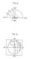
- figs. 12 and 13 show the performance obtained when using a panel P as a roof element whose perpendicular is contained in a vertical plane oriented east-west and is inclined towards the west.
- the directions of the sun at the three dates of the year already shown in fig. 10 are again shown in FIG. 12 and the corresponding paths of the sun identified with respect to the perpendicular to the panel in a graph of the same kind as that of FIG. 11 are shown in FIG. 13.
- the panel described provides an elegant and inexpensive solution to the problem of overhead lighting of industrial, commercial, cultural or other surfaces which require a light supply whose stability, homogeneity and distribution are controlled. It allows the creation of entirely transparent covers controlling the transfer of incident beams according to both their contribution in lighting and in heating. This solution can gradually replace the use of shed blankets, a solution which is known to be bulky and structurally complicated, while having performances which have never been entirely satisfactory.
- the elements and panels described can also be used as covers for opaque planes, either in facades or in roofs.
- many opaque planes, such as lighters, curtain facades benefit from being covered with the panel described.
- these plans can be subjected to an intense heating which often is harmful to the structure itself and which moreover has an unfavorable effect on the interior of the building.
- the coating structures of this kind with one or more elements as described above makes it possible to maximize the heating of the plans in cold periods and to minimize it in hot periods, therefore to reduce the costs of insulation and air conditioning of the building. Facades made entirely of glass can therefore be provided, with both climatic, aesthetic and cost advantages.
- the panels described can also be interesting by the fact that they can function in both meaning.
- a space protected by transparent walls can be configured thanks to the panels described so as to retain inside this space radiation which would tend to escape, whether it is solar radiation which would otherwise pass through the greenhouse from side to side or whether it is radiation emanating in a cold or nocturnal period from an artificial source located in the protected space.
- the transparent walls can be designed so that radiation from the outside is also used in the best climatic and light conditions.
Landscapes
- Life Sciences & Earth Sciences (AREA)
- Sustainable Development (AREA)
- Engineering & Computer Science (AREA)
- General Engineering & Computer Science (AREA)
- Optical Elements Other Than Lenses (AREA)
Priority Applications (1)
| Application Number | Priority Date | Filing Date | Title |
|---|---|---|---|
| EP86810048A EP0230854A1 (de) | 1986-01-27 | 1986-01-27 | Durchsichtige Platte als Teil eines Raumes in einem architektonischen Bau |
Applications Claiming Priority (1)
| Application Number | Priority Date | Filing Date | Title |
|---|---|---|---|
| EP86810048A EP0230854A1 (de) | 1986-01-27 | 1986-01-27 | Durchsichtige Platte als Teil eines Raumes in einem architektonischen Bau |
Publications (1)
| Publication Number | Publication Date |
|---|---|
| EP0230854A1 true EP0230854A1 (de) | 1987-08-05 |
Family
ID=8196449
Family Applications (1)
| Application Number | Title | Priority Date | Filing Date |
|---|---|---|---|
| EP86810048A Withdrawn EP0230854A1 (de) | 1986-01-27 | 1986-01-27 | Durchsichtige Platte als Teil eines Raumes in einem architektonischen Bau |
Country Status (1)
| Country | Link |
|---|---|
| EP (1) | EP0230854A1 (de) |
Citations (4)
| Publication number | Priority date | Publication date | Assignee | Title |
|---|---|---|---|---|
| US2993409A (en) * | 1957-01-02 | 1961-07-25 | Owens Illinois Glass Co | Skylights |
| US3185034A (en) * | 1961-09-26 | 1965-05-25 | Mississippi Glass Co | Patterned glass |
| FR1442592A (fr) * | 1964-05-25 | 1966-06-17 | Panneau laissant passer la lumière | |
| US4519675A (en) * | 1982-04-18 | 1985-05-28 | Bar Yonah Yitzchak | Selectively light transmitting panel |
-
1986
- 1986-01-27 EP EP86810048A patent/EP0230854A1/de not_active Withdrawn
Patent Citations (4)
| Publication number | Priority date | Publication date | Assignee | Title |
|---|---|---|---|---|
| US2993409A (en) * | 1957-01-02 | 1961-07-25 | Owens Illinois Glass Co | Skylights |
| US3185034A (en) * | 1961-09-26 | 1965-05-25 | Mississippi Glass Co | Patterned glass |
| FR1442592A (fr) * | 1964-05-25 | 1966-06-17 | Panneau laissant passer la lumière | |
| US4519675A (en) * | 1982-04-18 | 1985-05-28 | Bar Yonah Yitzchak | Selectively light transmitting panel |
Similar Documents
| Publication | Publication Date | Title |
|---|---|---|
| EP2132786B1 (de) | Flacher lichtkonzentrator mit geringer dicke | |
| EP1982226B1 (de) | Optisches system zur anzeige eines bildes auf der fläche eines sonnenkollektors | |
| US4411493A (en) | Seasonal control skylight glazing panel with passive solar energy switching | |
| FR2463254A1 (fr) | Procede et dispositif pour arreter ou laisser passer la lumiere solaire selon la saison | |
| EP0004242A1 (de) | Sonnenlicht Konzentrator | |
| FR3001213A1 (fr) | Substrat verrier texture pour batiment | |
| JP2004519700A (ja) | 多角反射式導光膜 | |
| EP3325734B1 (de) | Geneigtes und fixiertes jalousiesystem | |
| EP0230854A1 (de) | Durchsichtige Platte als Teil eines Raumes in einem architektonischen Bau | |
| EP1866495B1 (de) | Mauerstein oder blockförmiges bauelement und anordnung davon | |
| WO2021191557A1 (fr) | Bipv integrant un element transparent ou translucide a reflexion diffuse | |
| CH650546A5 (fr) | Panneau pour element de construction. | |
| BE569237A (de) | ||
| EP3480943B1 (de) | Sonnenenergiekollektorsystem | |
| EP2753884B1 (de) | Thermische vorrichtung mit lichtleiter | |
| EP1496320A1 (de) | Sonnenflachkollektor mit geringer Dicke | |
| FR2478281A1 (fr) | Procede et installation pour capter un rayonnement et pour l'exploiter dans une enceinte receptrice | |
| EP4399373B1 (de) | Architektur der heliodynamik | |
| EP0964112A1 (de) | Lichtdurchlässiges Paneel für Gebäude, das die natürliche Helligkeit innerhalb des Gebäudes verbessert | |
| FR3067822B1 (fr) | Vitrage photovoltaique dont la transparence aux infra-rouges proches s'adapte a la hauteur du soleil | |
| BE508972A (de) | ||
| FR2930051A1 (fr) | Paroi optique asymetrique | |
| FR3045597A1 (fr) | Vitrage dont la transparence aux infra-rouges s'adapte a la hauteur du soleil | |
| FR3033628A1 (fr) | Dispositif de production d'energie solaire optimise en fonction des saisons | |
| FR2892833A1 (fr) | Ecran afficheur statique a motif d'aspect variable |
Legal Events
| Date | Code | Title | Description |
|---|---|---|---|
| PUAI | Public reference made under article 153(3) epc to a published international application that has entered the european phase |
Free format text: ORIGINAL CODE: 0009012 |
|
| AK | Designated contracting states |
Kind code of ref document: A1 Designated state(s): BE CH DE FR GB IT LI SE |
|
| STAA | Information on the status of an ep patent application or granted ep patent |
Free format text: STATUS: THE APPLICATION IS DEEMED TO BE WITHDRAWN |
|
| 18D | Application deemed to be withdrawn |
Effective date: 19880206 |